1988 PONTIAC FIERO compression ratio
[x] Cancel search: compression ratioPage 138 of 1825
STEERING, SUSPENSION, TIRES AND WHEELS DIAGNOSIS 3.13
in doubt about the condition, compare with a
shock known to be good.
Noisy
For struts, follow Steps 1 through 3.
1. Check all mountings for proper torque. A loose
mounting will cause a noise.
2. If all mountings are intact, bounce the car as in
Step
4 (weak) to isolate the suspected unit.
3. If practical, ride with the owner to be sure you
understand the complaint, before proceeding to
next step.
4. If one of the rear shocks is noisy, the rear axle
should be supported at least enough to unload the
shock mounts. Disconnect the lower mounting of
the suspected shock. Quickly push the shock all
the way in, then all the way out.
A hissing noise
is normal.
5. Other objectionable noises may be detected by
stroking. Any sound other
than hissing is
abnormal; replace the shock.
Leaks
1. Fully extend the strut/shocks (wheels
unsupported) to expose the seal cover area for
inspection.
2. Look for
signs of leaks in the seal cover area.
3. A slight trace of fluid is NOT cause for
replacement; the seal permits some seepage to
lubricate the piston rod. There is a built in fluid
reserve to allow for seepage.
4. A leaking strut dampener/shock can easily be
found because there will be fluid around the seal
cover and an excessive amount of fluid on the
strut
dampener/shock. A leaking strut
dampener/shock must be replaced.
BENCH CHECKS
Strut Dampeners and Regular Shock Absorbers
(Standard and Firm Ride)
Regular strut dampenerdrear shocks use a
gas-filled cell in the fluid reservoir. Aeration or
foaming of the fluid is eliminated, as the gas and the
fluid cannot mix.
Proceed with the actual bench check as follows:
1. Clamp the strut dampener/shock UPSIDE
DOWN in the vise. Do not clamp on the reservoir
tube or the mounting threads. If a lag is noticed
when it is stroked, it means the gas-filled cell has
ruptured and replacement is necessary.
2. Pump strut dampener/shock by hand at various
rates of speed and note the resistance.
3. Rebound resistance normally is stronger than
compression resistance by about 2 to 1. However,
the resistance should be smooth and constant for
each stroking rate.
4. Compare with a strut dampener/ shock known to
be good.
5. It is normal to hear a hissing noise. The following
symptoms are abnormal and are reason for
replacement. A.
A skip or lag at reversal near mid-stroke.
B. A seize (except at either extreme end of
travel).
C. A noise (such as a grunt or squeal) after
completing one full stroke in both
directions.
D. A clicking noise at fast reversal.
E. Fluid leakage.
TIRE DIAGNOSIS
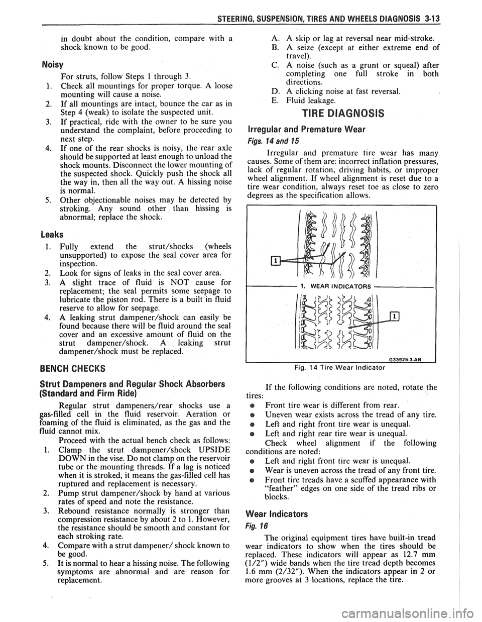
Irregular and Premature Wear
Figs. 14 and 15
Irregular and premature tire wear has many
causes. Some of them are: incorrect inflation pressures,
lack of regular rotation, driving habits, or improper
wheel alignment. If wheel alignment is reset due to a
tire wear condition, always reset toe as close to zero
degrees as the specification allows.
1. WEAR INDICATORS I
Fig. 14 Tire Wear Indicator
If the following conditions are noted, rotate the
tires:
@ Front tire wear is different from rear.
Uneven wear exists across the tread of any tire.
e Left and right front tire wear is unequal.
Left and right rear tire wear is unequal.
Check wheel alignment if the following
conditions are noted:
e Left and right front tire wear is unequal.
Wear is uneven across the tread of any front tire.
e Front tire treads have a scuffed appearance with
"feather" edges on one side of the tread ribs or
blocks.
Wear Indicators
Fig. 16
The original equipment tires have built-in tread
wear indicators to show when the tires should be
replaced. These indicators will appear as 12.7 mm
(1/2") wide bands when the tire tread depth becomes
1.6 mm (2/32"). When the indicators appear in 2 or
more grooves at
3 locations, replace the tire.
Page 270 of 1825
REAR AXLE 4B1-17
e. Assemble oiled oil seal, companion
flange, and new nut on pinion and tighten
nut to specified rotational torque while
rotating pinion forwards to seat bearing
correctly.
Important
NOTICE: If after tightening pinion nut, the
preload is excessive then the collapsible spacer
must be replaced and procedure (d) and (e)
repeated.
OPERATION OF LIMITED SLIP REAR AXLE
(CONE TYPE)
The cone-type limited-slip differential has several
definite operating characteristics. An understanding of
these characteristics is necessary as an aid to diagnosis.
During regular operation (straight ahead driving)
when both wheels rotate at equal speeds, there is an
approximately equal driving force delivered to each
wheel. When cornering, the inside wheel delivers extra
driving force causing slippage in both clutch cones.
Consequently, the operational life of the limited slip
unit is dependent upon equal rotation of both wheels
during straight ahead operation. If wheel rotation for
both rear wheels is not equal during straight ahead
operation, the limited-slip unit will constantly be
functioning as if the vehicle were cornering. This will
impose constant slippage on the clutch cones and will
eventually lead to abnormal wear on the clutch cones.
Therefore, it is important that there be no excessive differences in
the rear wheel tire sizes, air pressures, or
tire wear patterns. One indication of this condition is
"swerving on acceleration." If swerving on
acceleration is encountered, check the rear wheels for
different tire size, air pressure, or excessively different
wear patterns, and tread depths, before proceeding into
an overhaul operation.
Checking Limited-Slip Function
1. Place transmisison in Park position.
2. Raise rear of vehicle until one wheel is off the
ground, remove one wheel and tire assembly.
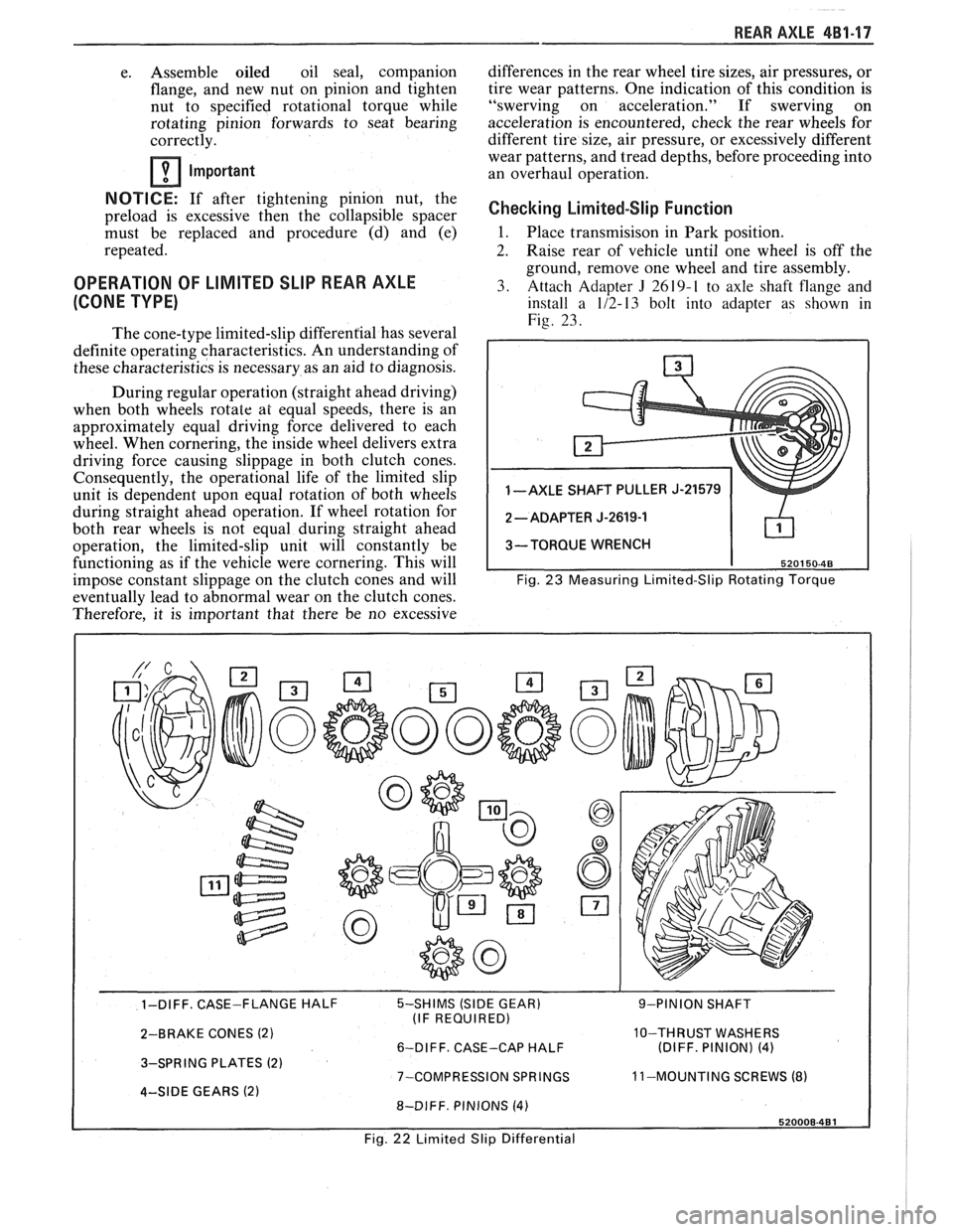
3. Attach Adapter
J 2619-1 to axle shaft flange and
install a 1/2-13 bolt into adapter as shown in
Fig. 23.
1 -AXLE SHAFT PULLER J-21579
3-TORQUE WRENCH
Fig.
23 Measuring Limited-Slip Rotating Torque
- - 1-DIFF. CASE-FLANGE HALF 5-SHIMS (SIDE GEAR) 9-PINION SHAFT
(IF REQUIRED)
2-BRAKE CONES
(2) 10-THRUST WASHERS
6-DIFF. CASE-CAP HALF (DIFF. PINION) (4)
3-SPRING PLATES (2) 7-COMPRESSION SPRINGS 11
-MOUNTING SCREWS (8) 4-SIDE GEARS (2) 8-DIFF. PINIONS (4)
Fig. 22 Limited Slip Differential
Page 374 of 1825
2.8 LITER V-6 8A2-23
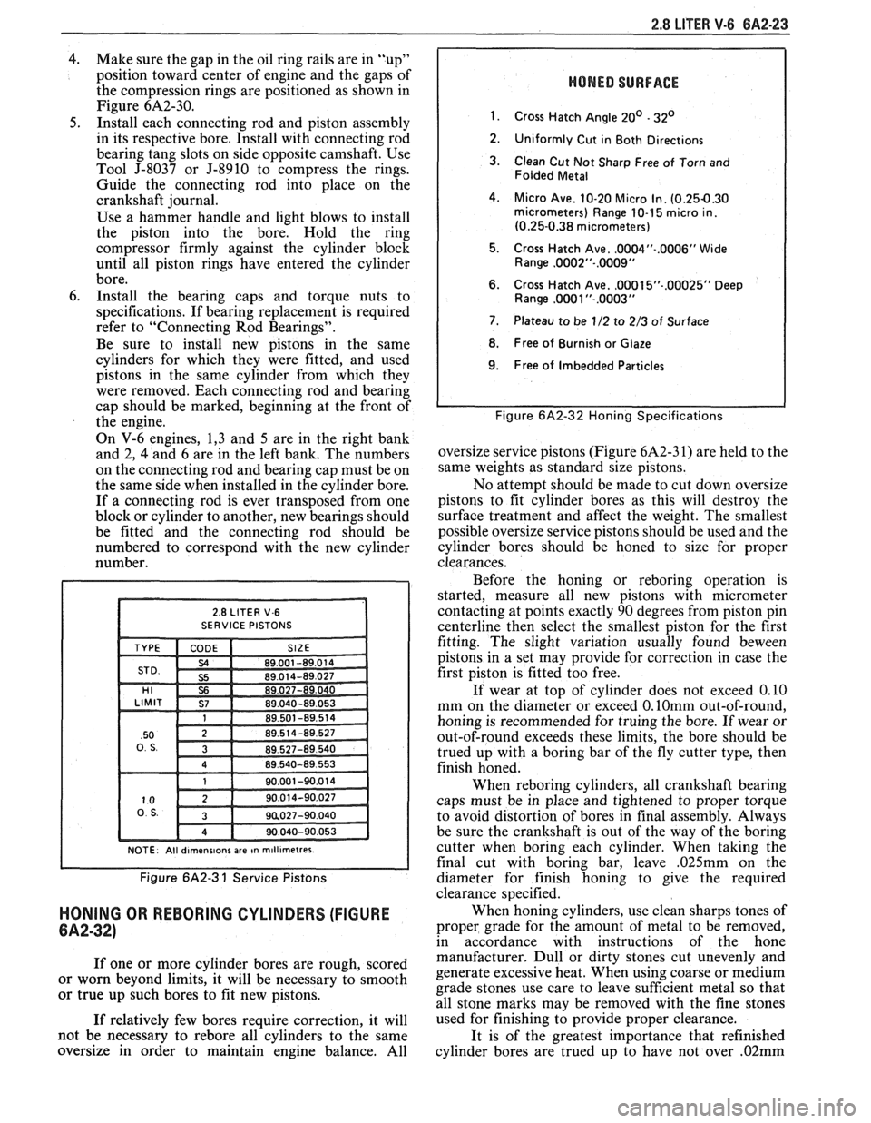
4. Make sure the gap in the oil ring rails are in "up"
position toward center of engine and the gaps of
the compression rings are positioned as shown in
Figure
6A2-30.
5. Install each connecting rod and piston assembly
in its respective bore. Install with connecting rod
bearing tang slots on side opposite camshaft. Use
Tool J-8037 or J-8910 to compress the rings.
Guide the connecting rod into place on the
crankshaft journal.
Use a hammer handle and light blows to install
the piston into the bore. Hold the ring
compressor firmly against the cylinder block
until all piston rings have entered the cylinder
bore.
6. Install the bearing caps and torque nuts to
specifications. If bearing replacement is required
refer to "Connecting Rod Bearings".
Be sure to install new pistons in the same
cylinders for which they were fitted, and used
pistons in the same cylinder from which they
were removed. Each connecting rod and bearing
cap should be marked, beginning at the front of
the engine.
On V-6 engines, 1,3 and 5 are in the right bank
and 2,
4 and 6 are in the left bank. The numbers
on the connecting rod and bearing cap must be on
the same side when installed in the cylinder bore.
If a connecting rod is ever transposed from one
block or cylinder to another, new bearings should
be fitted and the connecting rod should be
numbered to correspond with the new cylinder
number.
NOTE. All dlrnenslons are In rn~ll~rnetres.
Figure 6A2-3 1 Service Pistons
HONING OR REBORING CYLINDERS (FIGURE
6A2-32)
If one or more cylinder bores are rough, scored
or worn beyond limits, it will be necessary to smooth
or true up such bores to fit new pistons.
If relatively few bores require correction, it will
not be necessary to
rebore all cylinders to the same
oversize in order to maintain engine balance. All
HONED SURFACE
1.
Cross Hatch Angle 20' - 32'
2.
Uniformly Cut in Both Directions
3. Clean Cut Not Sharp Free of Torn and
Folded Metal
4. Micro Ave. 10-20 Micro In. (0.254.30 micrometers) Range 10-1 5 micro in.
(0.25-0.38 micrometers)
5. Cross Hatch Ave.
.0004"-.0006" Wide
Range ,0002"-.0009"
6. Cross Hatch Ave. ,0001 5"-.00025" Deep Ranw ,0081 "-.0003"
7. Plateau to be 1/2 to 2/3 of Surface
8. Free of Burnish or Glaze
I 9. Free of Imbedded Particles I
I I Figure 6A2-32 Honing Specifications
oversize service pistons (Figure 6A2-3 1) are held to the
same weights as standard size pistons.
No attempt should be made to cut down oversize
pistons to fit cylinder bores as this will destroy the
surface treatment and affect the weight. The smallest
possible oversize service pistons should be used and the
cylinder bores should be honed to size for proper
clearances.
Before the honing or
reboring operation is
started, measure all new pistons with micrometer
contacting at points exactly 90 degrees from piston pin
centerline then select the smallest piston for the first
fitting. The slight variation usually found
beween
pistons in a set may provide for correction in case the
first piston is fitted too free.
If wear at top of cylinder does not exceed 0.10
mm on the diameter or exceed
0.lOmm out-of-round,
honing is recommended for truing the bore. If wear or
out-of-round exceeds these limits, the bore should be
trued up with a boring bar of the fly cutter type, then
finish honed.
When
reboring cylinders, all crankshaft bearing
caps must be in place and tightened to proper torque
to avoid distortion of bores in final assembly. Always
be sure the crankshaft is out of the way of the boring
cutter when boring each cylinder. When taking the
final cut with boring bar, leave
,025mm on the
diameter for finish honing to give the required
clearance specified.
When honing cylinders, use clean sharps tones of
proper grade for the amount of metal to be removed,
in accordance with instructions of the hone
manufacturer. Dull or dirty stones cut unevenly and
generate excessive heat. When using coarse or medium
grade stones use care to leave sufficient metal so that
all stone marks may be removed with the fine stones
used for finishing to provide proper clearance.
It is of the greatest importance that refinished
cylinder bores are trued up to have not over
.02mm
Page 375 of 1825
6A2-24 2.8 LITER V-6
out-of-round or taper. Each bore must be final honed
to remove all stone or cutter marks and provide a
smooth surface. During final honing, each piston must
be fitted individually to the bore in which it will be
installed and should be marked to insure correct
installation.
After final honing and before the piston is
checked for fit, each cylinder bore must be thoroughly
washed to remove all traces of abrasives and then dried
thoroughly. The dry bore should then be brushed clean
with a power-driven fibre brush. If all traces of the
abrasives are not removed, rapid wear of new pistons
and rings will result.
FITTING PISTONS
1. Remove all rings
from pistons which will be
fitted. It is not necessary to separate rods from
pistons. If an excess amount of varnish or carbon
appears as a ridge at the top of the cylinder,
remove by scraping or sanding.
2. Wipe bores
and pistons clean, removing oil or
other foreign material. Select a piston-rod
assembly for the bore to be fitted (or piston and
pin if a new piston is being fitted) and position
down into the bore with the top of piston down.
The piston should fall free by its own weight
through the bore when when the bottom of the
piston skirt is 12 to 25mm from top of block.
Caution must be used to insure piston is not
damaged when it "falls" through the cylinder. If
it does not, the piston fit is too tight and another
piston should be selected until the piston will slide
freely through the bore without any force being
applied. Mark piston and bore for proper
assembly.
3. After a piston has been slected, which will slide
freely through a bore, it must be determined if
piston fit will be too loose. This is done by placing
a ,060 mm feeler gage for used pistons and a
.050
mm feeler gage for new pistons at least 150mm
long and not over 12mm wide, down into the
same bore with selected piston while holding
feeler to top of the bore.
Position selected piston and feeler down into the
bore until the bottom of the skirt is again 12 to
25 mm from top of block, being sure that the
feeler gage is
90" from the pin. If the piston hangs
on the feeler gage and does not fall free, it
indicates that the piston is correctly fitted to that
respective bore. Mark both piston and bore before
going to the next bore. If the piston fell free
during this check with the
.060mm feeler gage (.
050mm feeler gage for new pistons) then that
particular piston is too small for the bore and a
larger diameter piston will be required.
When checking more than one bore, it is very
possible that what may be a piston too small for one
bore will be a correct fit in another.
PISTON RINGS
When new piston rings are installed without
reboring cylinders, the glazed cylinder walls should be
slightly dulled, but without increasing the bore
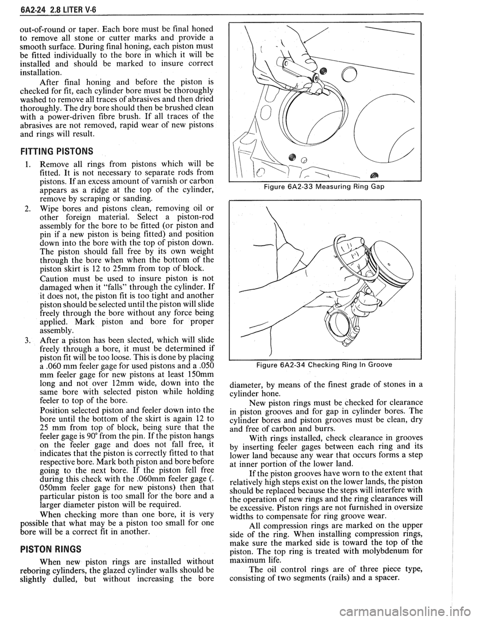
I I Figure 6A2-33 Measuring Ring Gap
i I
I I Figure 6A2-34 Checking Ring In Groove
diameter, by means of the finest grade of stones in a
cylinder hone.
New piston rings must be checked for clearance
in piston grooves and for gap in cylinder bores. The
cylinder bores and piston grooves must be clean, dry
and free of carbon and burrs.
With rings installed, check clearance in grooves
by inserting feeler gages between each ring and its
lower land because any wear that occurs forms a step
at inner portion of the lower land.
If the piston grooves have worn to the extent that
relatively high steps exist on the lower lands, the piston
should be replaced because the steps will interfere with
the operation of new rings and the ring clearances will
be excessive. Piston rings are not furnished in oversize
widths to compensate for ring groove wear.
All compression rings are marked on the upper
side of the ring. When installing compression rings,
make sure the marked side is toward the top of the
piston. The top ring is treated with molybdenum for
maximum life.
The oil control rings are of three piece type,
consisting of two segments (rails) and a spacer.
Page 377 of 1825
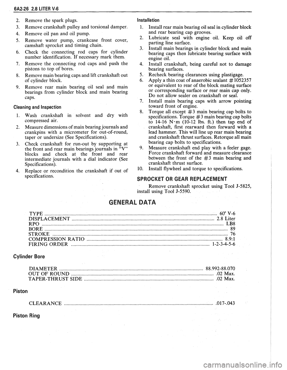
6A2-26 2.8 LITER V-6
2. Remove the spark plugs. Installation
3. Remove
crankshaft pulley and torsional damper. 1. Install rear main bearing oil seal in cylinder block
4. Remove oil pan and oil pump. and
rear bearing cap grooves.
5. Remove water pump, crankcase front cover, 2. Lubricate seal with engine oil. Keep oil off
camshaft sprocket and timing chain. parting
line surface.
3. Install main bearings in cylinder block and main
6. Check the connecting rod caps for cylinder
bearing caps then lubricate bearing surface with
number identification. If necessary mark them.
engine oil.
7. Remove the connecting rod caps and
push the
4. 1n;tall crankshaft, being careful not to damage
pistons to top of bores.
bearing surfaces.
8. Remove main bearing caps and lift crankshaft out 5. Recheck bearing clearances using plastigage.
of cylinder block. 6.
Apply a thin coat of anaerobic sealant
# 1052357
9. Remove rear
main bearing oil seal and main or
equivalent to rear of the block mating surface
bearings from cylinder block and main bearing or corresponding
surface or rear main cap only.
caps. Do
not allow sealer on crankshaft or seal.
7. Install main bearing caps with arrow pointing
Cleaning and Inspection toward front of engine.
8. Torque all except
#3 main bearing cap bolts to
1. Wash crankshaft in solvent and dry with
specifications. Torque
#3 main bearing cap bolts
compressed air. to 14-16
N-m (10-12 lbs. ft.) then tap end of
2. Measure
dimensions of main bearing journals and crankshaft, first rearward then forward with a
crankpins with a micrometer for out-of-round, lead
hammer. This will line up rear main bearing
taper or undersize (See Specifications). and crankshaft
thrust surfaces.
Retorque all main
3. Check
crankshaft for run-out by supporting at bearing
cap bolts to specifications.
the front and rear main bearings journals in "V" 9. Measure crankshaft
end play with a feeler gage.
blocks and check at the front and rear Force crankshaft forward and measure clearance
intermediate journals with a dial indicator (See between the front of the
#3 main bearing and
Specifications). crankshaft thrust surface.
4. Replace or recondition the crankshaft if out of 10.
Install flywheel and torque to specifications.
specifications.
SPROCKET OR GEAR REPLACEMENT
Remove crankshaft sprocket using Tool J-5825,
install using Tool J-5590.
GENERAL DATA
TYPE .................................................................................................................................... 60" V-6
DISPLACEMENT
............................................................................................................. 2.8 Liter
RPO
........................................................................................................................................... LB8
BORE ......................................................................................................................................... 89
STROKE
................................... .... ............................................................................................... 76
COMPRESSION RATIO
....................................................................................................... 8.9: 1
FIRING ORDER
.......................................................................................................... 1-2-3-4-5-6
Cylinder Bore
DIAMETER .............................................................................................................. 88.992-88.070
OUT OF ROUND
............................................................................................................. .02 Max.
TAPER-THRUST SIDE
................................................................................................. .02 Max.
Piston
CLEARANCE .................................................................................................................. .O 17-,043
Piston Ring
Page 378 of 1825
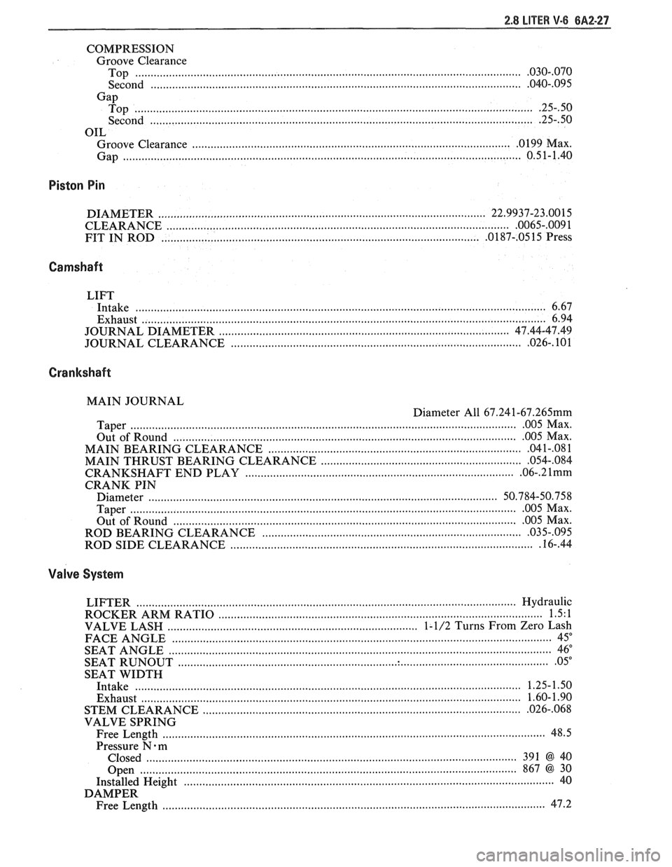
COMPRESSION Groove Clearance
............................................................................................................................ Top .030..070
................................................................................ Second .................................... .... .040.. 095
Gap ................................................................................................................................. Top .25..50
............................................................................................................................ Second .25..50
OIL
...................................................................................................... . Groove Clearance 0 199 Max
Gap
................................................................................................................................ 0.51-1.40
Piston Pin
DIAMETER ....................................................................................................... 22.9937-23.0015
........................................................................................................... CLEARANCE .0065-.009 1
FIT IN ROD
..................................................................................................... .0187-. 0515 Press
Camshaft
LIFT
Intake
................................................................................................................................... 6.67
Exhaust
.................................................................................................................................. 6.94
............................................................. ............................ JOURNAL DIAMETER .. 47.44-47.49
............................................................................................. JOURNAL CLEARANCE .026- . 101
Crankshaft
MAIN JOURNAL
Diameter All
67.241-67.265mm
............................................................................................................................. Taper 005 Max .
................................................................................................................ Out of Round 005
Max .
.................................................................................. MAIN BEARING CLEARANCE 04
1-.08 1
................................................................ MAIN THRUST BEARING CLEARANCE .054..084
...................................................................................... CRANKSHAFT END PLAY .06-. 2 1mm
CRANK PIN
Diameter
..................................... ... ......................................................................... 50.784-50.758
............................................................................................................................. Taper 005 Max .
............................................................................................................ Out of Round 005
Max .
.................................................... ROD BEARING CLEARANCE ......................... .. 03 5..095
................................................................................................ ROD SIDE CLEARANCE .16-. 44
Valve System
LIFTER ......................... .. ........................................................................................... Hydraulic
......................................................................................................... ROCKER ARM RATIO 1.5. 1
............................................................................... VALVE LASH 1- 1/2 Turns From Zero Lash
FACE ANGLE
........................................................................................................................... 45"
SEAT ANGLE ......................................................................................................................... 46"
....................................................................................................................... SEAT RUNOUT 05"
SEAT WIDTH
Intake
........................................................................................................................ 1.25-1.50
......................................................................................................................... Exhaust 1.60- 1.90
............................................................... STEM CLEARANCE ..................................... ... .026-. 068
VALVE SPRING
Free Length
......................................................................................................................... 48.5
Pressure N
. m
Closed
....................... .. .......................................................................................... 391 @40
Open
......................................................................................................................... 867 @30
Installed Height
........................................................................................................................ 40
DAMPER
........................................................................................................................... Free Length 47.2
Page 407 of 1825
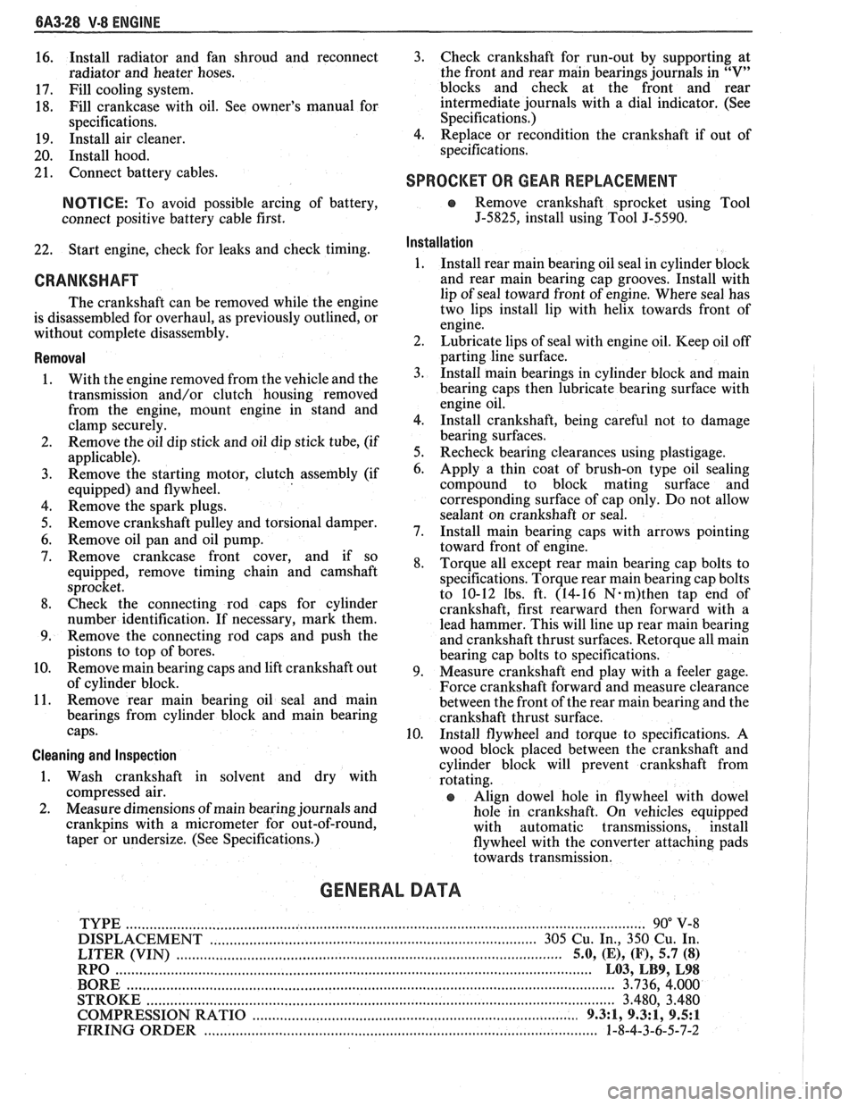
6A3-28 V-8 ENGINE
16. Install
radiator and fan shroud and reconnect
radiator and heater hoses.
17. Fill cooling system.
18. Fill
crankcase with oil. See owner's manual for
specifications.
19. Install air cleaner.
20. Install hood.
21. Connect battery cables.
NOTICE: To avoid possible arcing of battery,
connect positive battery cable first.
22. Start engine, check for leaks and check timing.
CRANKSHAFT
The crankshaft can be removed while the engine
is disassembled for overhaul, as previously outlined, or
without complete disassembly.
Removal
With the engine removed from the vehicle and the
transmission and/or clutch housing removed
from the engine, mount engine in stand and
clamp securely.
Remove the oil dip stick and oil dip stick tube, (if
applicable).
Remove the starting motor, clutch assembly (if
equipped) and flywheel.
Remove the spark plugs.
Remove crankshaft pulley and torsional damper.
Remove oil pan and oil pump.
Remove crankcase front cover, and if so
equipped, remove timing chain and camshaft
sprocket.
Check the connecting rod caps for cylinder
number identification. If necessary, mark them.
Remove the connecting rod caps and push the
pistons to top of bores.
Remove main bearing caps and lift crankshaft out
of cylinder block.
Remove rear main bearing oil seal and main
bearings from cylinder block and main bearing
caps.
Cleaning and Inspection
1. Wash crankshaft in solvent and dry with
compressed air.
2. Measure dimensions of main bearing journals and
crankpins with a micrometer for out-of-round,
taper or undersize. (See Specifications.) 3.
Check crankshaft for run-out by supporting at
the front and rear main bearings journals in
"V"
blocks and check at the front and rear
intermediate journals with a dial indicator. (See
Specifications.)
4. Replace or recondition the crankshaft if out of
specifications.
SPROCKET OR GEAR REPLACEMENT
e Remove crankshaft sprocket using Tool
5-5825, install using Tool J-5590.
Installation
1.
Install rear main bearing oil seal in cylinder block
and rear main bearing cap grooves. Install with
lip of seal toward front of engine. Where seal has
two lips install lip with helix towards front of
engine.
2. Lubricate lips of seal with engine oil. Keep oil off
parting line surface.
3. Install main bearings in cylinder block and main
bearing caps then lubricate bearing surface with
engine oil.
4. Install crankshaft, being careful not to damage
bearing surfaces.
5. Recheck bearing clearances using plastigage.
6. Apply a thin coat of brush-on type oil sealing
compound to block mating surface and
corresponding surface of cap only. Do not allow
sealant on crankshaft or seal.
7. Install main bearing caps with arrows pointing
toward front of engine.
8. Torque all except rear main bearing cap bolts to
specifications. Torque rear main bearing cap bolts
to 10-12 lbs. ft. (14-16
N.m)then tap end of
crankshaft, first rearward then forward with a
lead hammer. This will line up rear main bearing
and crankshaft thrust surfaces.
Retorque all main
bearing cap bolts to specifications.
9. Measure crankshaft end play with a feeler gage.
Force crankshaft forward and measure clearance
between the front of the rear main bearing and the
crankshaft thrust surface.
10. Install flywheel and torque to specifications. A
wood block placed between the crankshaft and
cylinder block will prevent crankshaft from
rotating.
Align dowel hole in flywheel with dowel
hole in crankshaft. On vehicles equipped
with automatic transmissions, install
flywheel with the converter attaching pads
towards transmission.
GENERAL DATA
TYPE .................................................................................................................................. 90" V-8
DISPLACEMENT
............................................................................... 305 Cu. In., 350 Cu. In.
......................................................... LITER (VIN) ................................... ...... 5.0, (E), (F), 5.7 (8)
RPO ......................................................................................................................... L03, LB9, L98
BORE ........................................................................................................................ 3.736, 4.000
STROKE
........................... .. ....................................................................................... 3.480, 3.480
COMPRESSION RATIO
................................................................................... 931, 931, 9.5:1
FIRING ORDER .................................................................................................... 1-8-4-3-6-5-7-2
Page 472 of 1825
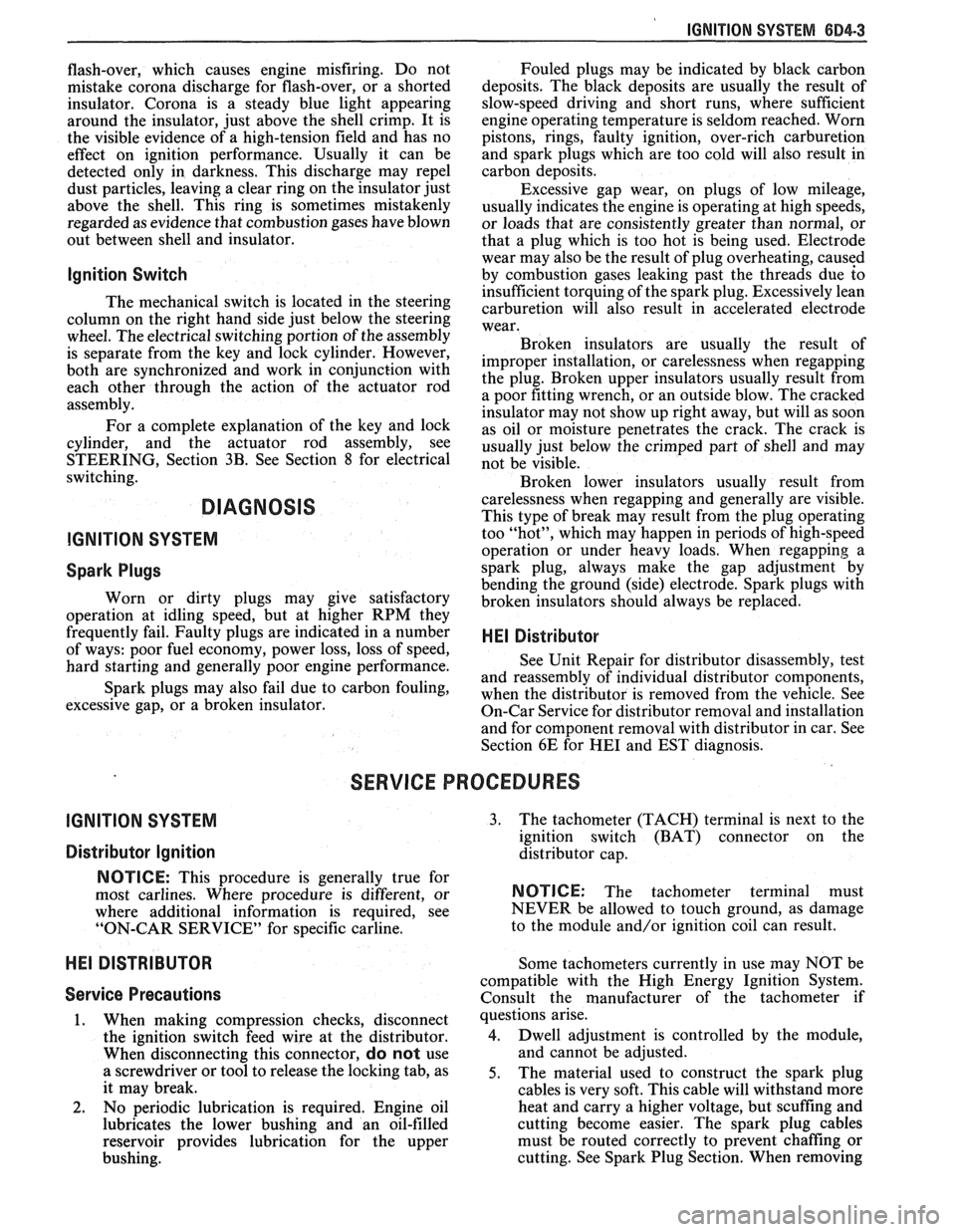
IGNITION SYSTEM 6B4-3
flash-over, which causes engine misfiring. Do not
mistake corona discharge for flash-over, or a shorted
insulator. Corona is a steady blue light appearing
around the insulator, just above the shell crimp. It is
the visible evidence of a high-tension field and has no
effect on ignition performance. Usually it can be
detected only in darkness. This discharge may repel
dust particles, leaving a clear ring on the insulator just
above the shell. This ring is sometimes mistakenly
regarded as evidence that combustion gases have blown
out between shell and insulator.
lgnition Switch
The mechanical switch is located in the steering
column on the right hand side just below the steering
wheel. The electrical switching portion of the assembly
is separate from the key and lock cylinder. However,
both are synchronized and work in conjunction with
each other through the action of the actuator rod
assembly.
For a complete explanation of the key and lock
cylinder, and the actuator rod assembly, see
STEERING, Section
38. See Section 8 for electrical
switching.
DIAGNOSIS
IGNITION SYSTEM
Spark Plugs
Worn or dirty plugs may give satisfactory
operation at idling speed, but at higher RPM they
frequently fail. Faulty plugs are indicated in a number
of ways: poor fuel economy, power loss, loss of speed,
hard starting and generally poor engine performance.
Spark plugs may also fail due to carbon fouling,
excessive gap, or a broken insulator. Fouled plugs may
be indicated by black carbon
deposits. The black deposits are usually the result of
slow-speed driving and short runs, where sufficient
engine operating temperature is seldom reached. Worn
pistons, rings, faulty ignition, over-rich carburetion
and spark plugs which are too cold will also result in
carbon deposits.
Excessive gap wear, on plugs of low mileage,
usually indicates the engine is operating at high speeds,
or loads that are consistently greater than normal, or
that a plug which is too hot is being used. Electrode
wear may also be the result of plug overheating,
causcd
by combustion gases leaking past the threads due to
insufficient torquing of the spark plug. Excessively lean
carburetion will also result in accelerated electrode
wear.
Broken insulators are usually the result of
improper installation, or carelessness when regapping
the plug. Broken upper insulators usually result from
a poor fitting wrench, or an outside blow. The cracked
insulator may not show up right away, but will as soon
as oil or moisture penetrates the crack. The crack is
usually just below the crimped part of shell and may
not be visible.
Broken lower insulators usually result from
carelessness when regapping and generally are visible.
This type of break may result from the plug operating
too "hot", which may happen in periods of high-speed
operation or under heavy loads. When regapping a
spark plug, always make the gap adjustment by
bending the ground (side) electrode. Spark plugs with
broken insulators should always be replaced.
HE1 Distributor
See Unit Repair for distributor disassembly, test
and reassembly of individual distributor components,
when the distributor is removed from the vehicle. See
On-Car Service for distributor removal and installation
and for component removal with distributor in car. See
Section 6E for
HE1 and EST diagnosis.
SERVICE PROCEDURES
IGNITION SYSTEM
Distributor Ignition
NOTICE: This procedure is generally true for
most carlines. Where procedure is different, or
where additional information is required, see
"ON-CAR SERVICE" for specific
carline.
HE1 DISTRIBUTOR
Service Precautions
1. When making compression checks, disconnect
the ignition switch feed wire at the distributor.
When disconnecting this connector,
do not use
a screwdriver or tool to release the locking tab, as
it may break.
2. No periodic lubrication is required. Engine oil
lubricates the lower bushing and an oil-filled
reservoir provides lubrication for the upper
bushing. 3.
The tachometer (TACH) terminal is next to the
ignition switch (BAT) connector on the
distributor cap.
NOTICE: The tachometer terminal must
NEVER be allowed to touch ground, as damage
to the module and/or ignition coil can result.
Some tachometers currently in use may NOT be
compatible with the High Energy Ignition System.
Consult the manufacturer of the tachometer if
questions arise.
4. Dwell adjustment is controlled by the module,
and cannot be adjusted.
5. The material used to construct the spark plug
cables is very soft. This cable will withstand more
heat and carry a higher voltage, but scuffing and
cutting become easier. The spark plug cables
must be routed correctly to prevent
chafing or
cutting. See Spark Plug Section. When removing