1988 PONTIAC FIERO wheel torque
[x] Cancel search: wheel torquePage 2 of 1825
1988
SER
This manual applies to the 1988 Pontiac Firebird Models.
It contains the latest product information available at the
time of publication approval. lnformation pertaining to
the operation of the vehicle is contained in the Owner's
Manual which accompanies each vehicle. The right is
reserved to make changes at any time without notice.
Any references to brand names in this manual is intended
merely as an example of the types of
lubricant% tools,
materials, etc, recommended for use in servicing 1988
Pontiac Models. In all cases, an equivalent may be used.
PONTIAC DIVISION
GENERAL
MOTORS CORPORATION
PONTIAC, MICHIGAN 48053
1987 General Motors Corp. All Rights Reserved.
No part of this publication may be reproduced, stored in any
retrieval system or transmitted in any form or by any means,
including but not limited to electronic, mechanical,
photocopying, recording or otherwise, without the prior written
permission of General Motors Corp. This includes all text,
illustrations, tables and charts.
S-881 OF 9-87 Printed in Canada
TABLE OF CONTENTS
SECTION NAME
GENERAL INFORMATION
OA. General lnformation
OB. Maintenance & Lubrication
1 SECT.
HEATING AND AIR CONDITIONING
1A. Heating and Ventilation
1 B. Air Conditioning
1D1. R-4 AIC Com~ressor Overhaul
FRAME AND BUMPERS
2B. Bumpers 2C. Chassis Sheet Metal
STEERING, SUSPENSION, WHEELS
AND TIRES
3. Diagnosis
3A. Wheel Alignment
3B5. Steering Wheels and Columns 3B6. Steering Linkage 3B7. Power Steering Gear and Pump
3C. Front Suspension
3D. Rear Suspension
3E. Tires and Wheels
FINAL DRIVE
4A. Propeller Shaft
4B. Rear Axle
4B1. Bora-Warner Axle
BRAKES 5. Brakes 5A3. Comoosite Master Cvlinder 5B1. Disc r rake Caliper ~ssembly - 300013100 Series 5B6. Disc Brake Caliper Assembly - 3548
Series
5C3. Direct Torque Drum Brake Assembly 5D2. Power Head Assembly - Tandem Diaohraam 5F. ~~ecifications and Special Tools
ENGINE 6. Engine General lnformation 6A2. 2.8L 6A3. 5.OL & 5.7L 6B. Engine Cooling
6C. En~ine Fuel
6D. ~ngine Electrical 6D1. Battery 6D2. Cranking System 6D3. Charging System 6D4. Ignition System 6D5. Engine Wiring
6E. Driveabilitv and Emissions
6E2. ~missions' 6E3. Emissions - PFI
6F. Engine Exhaust
TRANSMISSION 7A. Automatic Transmission - General
lnformation
7A1. Automatic Transmission - On-Car
Service
700R4. Automatic Transmission Hydraulic Diagnosis
700R4. Automatic Transmission Unit Repair
76. 5-Speed Manual Transmission
7C. Clutch
CHASSIS ELECTRICAL 8A. Electrical Diagnosis
8B. Lighting and Horns
8C. Instrument
Panel, Gages
& Console
8E. Windshield Wiper &Washer System
ACCESSORIES 9A. Radio Systems and Antennas 9B. Cruise Control 9G. Miscellaneous Accessories
I BODY SERVICE MANUAL END
OF
MANUAL
Page 16 of 1825

- -
GENERAL INFORMATION OA-13
LIST OF AUTOMOTIVE ABBREVIATIONS
WHICH MAY
BE USED IN THIS MANUAL
A-6 - Axial 6 Cyl. A C Compressor AIC - Air Conditioning
ACC - Auto'matic Climate Control
EMF
- Electromotive Force PAIR - Pulse Air Injection Reaction System
EMR - Electronic Module Retard
P B - Power Brakes
EOS - Exhaust Oxygen Sensor
PCV - Positive Crankcase Ventilation
ESC - Electronic Spark Control
PECV - Power Enrichment Control Valve
APT
- Adjustable Part Throttle
AT - Automatic Transmission
ATC - Automatic Temperature Control
ATDC
- After Top Dead Center
FMVSS
- Federal Motor Vehicle Safety BAR0 - Barometric Absolute Pressure Sensor
Ft. Lb. - Foot Pounds (Torque)
Bat. + - Positive Terminal FWD - Front Wheel Drive
- Four Wheel Drive
BHP - Brake Horsepower 4 x 4 - Four Wheel Drive
BP - Back Pressure
BTDC - Before Top Dead Center
HD - Heavy Duty HE1 - High Energy Ignition
Cat. Conv. - Catalytic Converter
CC - Catalytic Converter
- Cubic Centimeter - Converter Clutch
CCC - Computer Command Control
HVM
- Heater-Vent-Module
IAC
- ldle Air Control CCOT - Cycling Clutch (Orifice) Tube IC - Integrated Circuit CCP - Controlled Canister Purge
ID - Identification
C.E. - Check Engine - Inside Diameter
CEAB - Cold Engine Airbleed ILC - Idle Load Compensator
CEMF - Counter Electromotive Force I/P - Instrument Panel
CID - Cubic Inch Displacement ISC - Idle Speed Control CLOOp - Closed Loop
CLCC - Closed Loop Carburetor Control km - Kilometers
CP
- Canister Purge kmiL - Kilometers Liter (mpg) Cu. In. - Cubic Inch kPa - Kilopascals
CV - Constant Velocity
Cyl.
- Cylinder(s)
L-4 - Four Cylinder In-Line (Engine)
DBB - Dual Bed Bead L-6 - Six Cylinder In-Line (Engine)
DBM - Dual Bed Monolith
LF - Left Front DEFl - Digital Electronic Fuel Injection LR - Left Rear DFI - Digital Fuel Injection
Diff. - Differential Man. Vac. - Manifold Vacuum Distr. - Distributor MAP - Manifold Absolute Pressure
EAC
- Electric Air Control Valve
EAS - Electric Air Switching Valve MPG - Miles Per Gallon
ECC - Electronic Comfort Control
MPH - Miles Per Hour
ECM - Electronic Control Module MT - Manual Transmission
N.m - Newton Metres (Torque)
Emission Control
Fig. 014-15 -- Common Abbreviations
Page 18 of 1825
MAINTENANCE AND LUBRICATION OB-1
SECTION OB
NTENANCE AND LUBR
CONTENTS
Maintenance Schedule, Gasoline .............................................. OB-l
Maintenance Schedules I and 11 .............................................. OB-2
Owner Inspections
......................................................... OB-3
Recommended Fluids and Lubricants ......................................... OB-6
PASSENGER CAR MAINTENANCE SCHEDULE
VEHICLES
WITH GASOLINE ENGINE
NORMAL CAR USE ITEM 4
The maintenance services contained in Schedules I Carburetor or Throttle Body Mounting Bolt
and 11 are based on the assumption that your car will be Torque* used as designed:
Check torque of mounting bolts and/or nuts. @ To carry passengers and cargo within the limits
shown on the Tire Placard located on the edge of the ITEM 5 driver's door.
@ On reasonable road surfaces within legal driving Engine Idle Speed Adjustment*
limits. (Engines
without Idle Speed Control or Idle Air
Control) - Adjust to specifications shown on the under- @ On unleaded gasoline.
hood label. If no specifications are shown on the label, no
adjustment is necessary. Calibrated test equipment must
EXPLANATION OF SCHEDULED MAINTENANCE be used. SERVICES
The services listed in Maintenance Scheduies I and ITEM 6
11 are further explained below. When the following main- ~i~~ and wheel aotation tenance services are performed, make sure all parts are
replaced and all necessary repairs are done before driving To equalize wear and obtain maximum tire life,
your car. Be sure to use the proper fluid and lubricants as rotate in accordance with patterns shown in Owner's
shown in Figure OB-2. Manual.
ITEM 1
Engine Oil and Oil Filter Change*
ALWAYS USE SFICC OR SF/CD ENERGY CON-
SERVING OILS OF PROPER VISCOSITY
- Also.
always change oil and filter as soon as possible after
driving in a dust storm. See your Owner's Manual for
further details.
ITEM 2
Chassis Lubrication
Lubricate all grease fittings in suspension and steer-
ing linkage. Lubricate
transmissionltransaxle shift
linkage, parking brake cable guides, underbody contact
points and linkage. Also lubricate clutch cross shaft lever
every
30,000 miles (50 000 km) on rear-wheel-drive cars
only.
ITEM 3
Carburetor Choke and Hoses*
If your car is equipped with a carburetor, verify that
choke and vacuum break work properly and are within
specifications. Correct any binding caused by damage or
gum on the choke shaft. Inspect hoses for proper hookup,
cracks, chafing or decay. Correct as necessary.
Vacuum or A.I.R. Pump Drive Belt Inspection*
When a separate belt is used to drive the vacuum or
A.I.R.
pump, inspect it for cracks, fraying, wear and
proper tension. Adjust or replace as needed.
ITEM 8
Cooling System Service*
Drain, flush and refill system with new coolant. See
your Owner's Manual
for further details.
ITEM 9
Wheel Bearing Repack (Rear-Wheel-Drive Cars
Only Except Corvette)
Clean and repack front wheel bearings at each brake
relining or 15,000 miles
(25 000 km), whichever comes
first, when car is used in such service as police, taxi or
door-to-door delivery. If you do not use your car in such
service, clean and repack bearings at each brake relining
or 30,000 miles
(50 000 km), whichever comes first.
Corvette models do not require wheel bearing repack.
Page 135 of 1825

3-10 STEERING, SUSPENSION, TIRES AND WHEELS DIAGNOSIS
Reminder Keeps Operating With Key In Lock
Cylinder, Driver's Door Open Or Closed; Ceases
When Key Is Removed
Inspect
s Door jamb switch on driver's side misadjusted or
inoperative.
e Wire from signal switch to door jamb switch
shorted.
A. This condition indicates the lock cylinder or
the reminder switch is at fault. To verify,
check for continuity at the
"E" and "F"
male column connector contacts, with the
key removed from the lock cylinder. If
continuity exists, the fault is in the column.
B. Insert the key into the lock, then turn the
lock toward the "Start" position. If the
reminder stops when the key is in the
"Run" position or when it is turned past
"Run" toward "Start," the problem is a
sticky lock cylinder actuator.
COLUMN-MOUNTED DIMMER SWITCH
No "Low" or "High" Beam
Inspect
e Loose connector at dimmer switch
e Improper adjustment
e Internally damaged or worn switch. Check the
continuity on the switch at the It. green and at the
tan switch terminals by pushing in the plunger all
the way.
A click should be heard. If there is no
continuity, replace the dimmer switch. If there is
continuity, refer
to'section 8A for electricaldiag-
nosis.
PIVOT AND SWITCH ASSEMBLY
Switch Inoperative: No "Low," "High" and/or
"Wash"
e Loose body-to-switch connector
a Broken or damaged switch
Internally damaged or worn switch. Connect a
new switch without removing the old one. If the
system functions, replace the switch. If the
system doesn't function, refer to Section
8A for
electrical diagnosis.
STEERING GEAR AND PUMP LEAKS
General Procedure
Inspect
s Overfilled reservoir
s Fluid aeration and overflow
e , Hose connections
Verify exact point of leakage Example:
Torsion bar, stub shaft and
adjuster seals are close together; the exact
spot where the system is leaking may not be
clear.
Example: The point from which the fluid is
dripping is not necessarily the point where
the system is leaking; fluid overflowing from
the reservoir, for instance.
e When service is required:
A. Clean leakage area upon disassembly.
B. Replace leaking seal.
C. Check component sealing surfaces for
damage.
D. Reset bolt torque to specifications, where
required.
Some complaints about the power steering system
may be reported as:
A. Fluid leakage on garage floor
B. Fluid leaks visible on steering gear or pump
C. Growling noise, especially when parking or
when engine is cold
D. Loss of power steering when parking
E. Heavy steering effort
When troubleshooting these kinds of complaints,
check for an external leak in the power steering system.
For further diagnosis of leaks, refer to External
Leakage Check in this section.
External Leakage Check
Fig. 12
The purpose of this procedure is to pinpoint the
location of the leak.
In some cases, the leak can easily be located. But,
seepage-type leaks may be more difficult to isolate. To
locate seepage leaks, use the following method.
1. With the engine off, wipe dry the complete power
steering system.
2. Check the fluid level in the pump's reservoir. Add
fluid if necessary.
3. Start the engine, then turn the steering wheel
from stop to stop several times. Do not hold it at
a stop for any length of time, as this can damage
the power steering pump. It is easier if someone
else operates the steering wheel while you search
for the seepage.
4. Find the exact area of the leak and repair leak.
SEAL REPLACEMENT
RECOMMENDATIONS
Lip seals, which seal rotating shafts, require
special treatment. This type of seal is used on the
steering gear and on the drive shaft of the pump. When
there is a leak in one of these areas, always replace the
seal(s), after inspecting and thoroughly cleaning the
sealing surfaces. Replace the shaft only if very severe
pitting is found. If the corrosion in the lip seal contact
zone is slight, clean the surface of the shaft with crocus
cloth. Replace the shaft only if the leakage cannot be
stopped by first smoothing with crocus cloth.
Page 138 of 1825
STEERING, SUSPENSION, TIRES AND WHEELS DIAGNOSIS 3.13
in doubt about the condition, compare with a
shock known to be good.
Noisy
For struts, follow Steps 1 through 3.
1. Check all mountings for proper torque. A loose
mounting will cause a noise.
2. If all mountings are intact, bounce the car as in
Step
4 (weak) to isolate the suspected unit.
3. If practical, ride with the owner to be sure you
understand the complaint, before proceeding to
next step.
4. If one of the rear shocks is noisy, the rear axle
should be supported at least enough to unload the
shock mounts. Disconnect the lower mounting of
the suspected shock. Quickly push the shock all
the way in, then all the way out.
A hissing noise
is normal.
5. Other objectionable noises may be detected by
stroking. Any sound other
than hissing is
abnormal; replace the shock.
Leaks
1. Fully extend the strut/shocks (wheels
unsupported) to expose the seal cover area for
inspection.
2. Look for
signs of leaks in the seal cover area.
3. A slight trace of fluid is NOT cause for
replacement; the seal permits some seepage to
lubricate the piston rod. There is a built in fluid
reserve to allow for seepage.
4. A leaking strut dampener/shock can easily be
found because there will be fluid around the seal
cover and an excessive amount of fluid on the
strut
dampener/shock. A leaking strut
dampener/shock must be replaced.
BENCH CHECKS
Strut Dampeners and Regular Shock Absorbers
(Standard and Firm Ride)
Regular strut dampenerdrear shocks use a
gas-filled cell in the fluid reservoir. Aeration or
foaming of the fluid is eliminated, as the gas and the
fluid cannot mix.
Proceed with the actual bench check as follows:
1. Clamp the strut dampener/shock UPSIDE
DOWN in the vise. Do not clamp on the reservoir
tube or the mounting threads. If a lag is noticed
when it is stroked, it means the gas-filled cell has
ruptured and replacement is necessary.
2. Pump strut dampener/shock by hand at various
rates of speed and note the resistance.
3. Rebound resistance normally is stronger than
compression resistance by about 2 to 1. However,
the resistance should be smooth and constant for
each stroking rate.
4. Compare with a strut dampener/ shock known to
be good.
5. It is normal to hear a hissing noise. The following
symptoms are abnormal and are reason for
replacement. A.
A skip or lag at reversal near mid-stroke.
B. A seize (except at either extreme end of
travel).
C. A noise (such as a grunt or squeal) after
completing one full stroke in both
directions.
D. A clicking noise at fast reversal.
E. Fluid leakage.
TIRE DIAGNOSIS
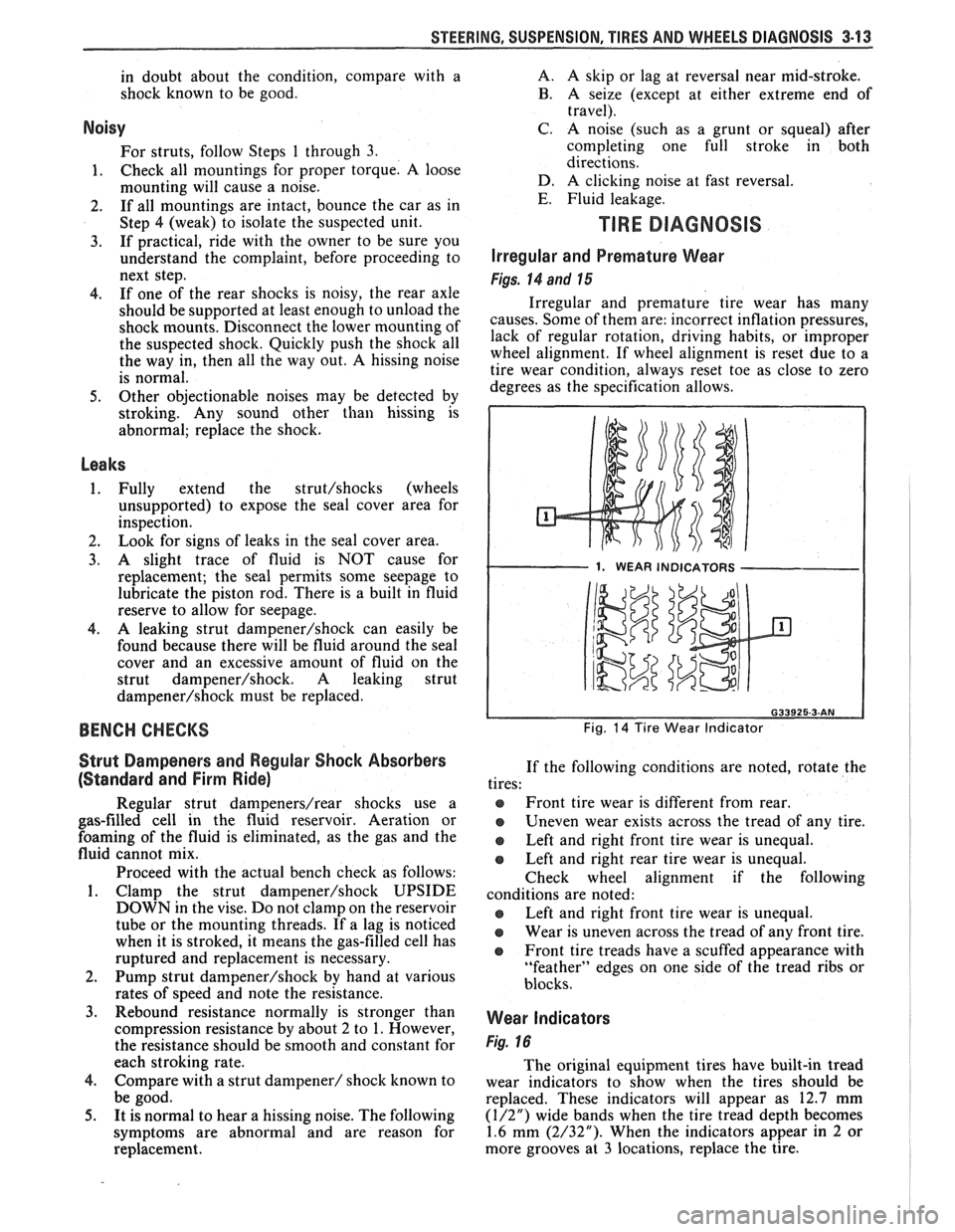
Irregular and Premature Wear
Figs. 14 and 15
Irregular and premature tire wear has many
causes. Some of them are: incorrect inflation pressures,
lack of regular rotation, driving habits, or improper
wheel alignment. If wheel alignment is reset due to a
tire wear condition, always reset toe as close to zero
degrees as the specification allows.
1. WEAR INDICATORS I
Fig. 14 Tire Wear Indicator
If the following conditions are noted, rotate the
tires:
@ Front tire wear is different from rear.
Uneven wear exists across the tread of any tire.
e Left and right front tire wear is unequal.
Left and right rear tire wear is unequal.
Check wheel alignment if the following
conditions are noted:
e Left and right front tire wear is unequal.
Wear is uneven across the tread of any front tire.
e Front tire treads have a scuffed appearance with
"feather" edges on one side of the tread ribs or
blocks.
Wear Indicators
Fig. 16
The original equipment tires have built-in tread
wear indicators to show when the tires should be
replaced. These indicators will appear as 12.7 mm
(1/2") wide bands when the tire tread depth becomes
1.6 mm (2/32"). When the indicators appear in 2 or
more grooves at
3 locations, replace the tire.
Page 148 of 1825
-
WHEEL. ALIGNMENT 3A-1
SECTION 3A
WHEEL AL GNMENT
NOTICE: These fasteners are important attaching Do not use a replacement part of lesser quality or
parts, in that they could affect the performance of substitute
design. Torque values must be used as
vital components and systems, and/or could result specified during reassembly to assure proper
in major repair expense. They must be replaced retention of these parts. For prevailing torque
with one of the same part number or with an
nut(s) and bolt(s), refer to the "Reuse of Prevailing
equivalent part if replacement becomes necessary. torque
Nut(s) and Bolt(s)" chart in Section 0.
General Description ...................... .. ...... 3A- 1 On-Car Service ........................ .. ........... 3A-2
Caster .................... .. ............................ 3A- 1 Caster and Camber Adjustment .................. 3A-2
..................................... Camber ................... .. .............................. 3A-I Toe-In Adjustment 3A-2
Toe.. ................................................. 3A- 1 Axle Housing Alignment ......................... .... 3A-4
Preliminary Checks Prior to Specifications ....................... ... ............... 3A-4
Adjusting Alignment ..................... ...... 3A- 1
GENERAL DESCRIPmIOMI
Wheel alignment refers to the angular they tend to roll parallel on the road when the car is
relationship between the wheels, the suspension moving.
attaching parts and the ground.
PRELIMINARY CHECKS PRIOR TO ADJUSTING
CASTER ALIGNMENT
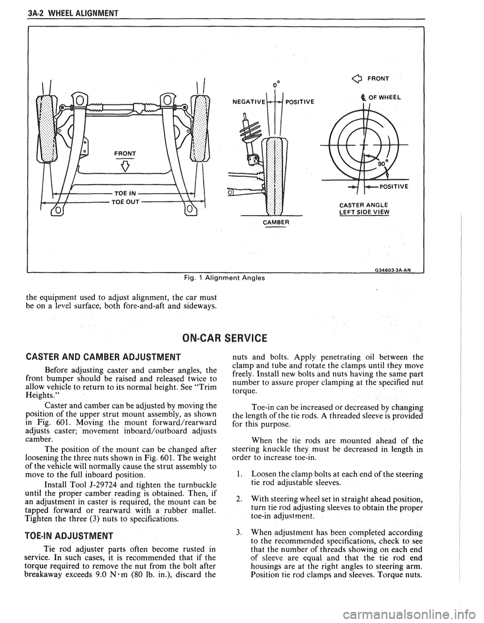
Figure 1
Caster is the amount the top of the strut is tilted
forward or rearward from the vertical. When the strut
tilts rearward, the center is "positive"
(+). The
amount of tilt is measured in degrees from vertical.
CAMBER
Figure 1
Camber is the tilting of the wheels from the
vertical when viewed from the front of the car. When
the wheels tilt outward at the top, the camber is said
to be positive
(+). When the wheels tilt inward at the
top, the camber is said to be negative
(-). The amount
of tilt is measured in degrees from the vertical and this
measurement is called the camber angle.
TOE
Figure i
Toe is a measurement of how much the front of
the wheels are turned in or out from a straight-ahead
position. When the wheels are turned in, toe is
"positive"
(+). When the wheels are turned out, toe
is "negative"
(-). The actual amount of toe-in is
normally only a fraction of a degree. The purpose of a
toe specification is to ensure parallel rolling of the
wheels (excessive toe-in or toe-out may increase tire
wear). Toe also serves to offset the small deflections of
the wheel support system which occur when the car is
rolling forward. In other words, even when the wheels
are set to toe-in slightly when the car is standing still, Steering
and vibration complaints are not always
the result of improper alignment. Another possibility
is tire "lead" due to worn or improperly manufactured
tires. "Lead" is the deviation of the car from a straight
path on a level road without hand pressure on the
steering wheel. Section
3 of this manual contains a
procedure for determining the presence of a tire lead
problem.
Before making any adjustment affecting wheel
alignment, make the following checks to ensure correct
alignment readings and alignment adjustments:
1. Check all tires for proper inflation pressures and
approximately the same tread wear.
2. Hub and bearing assemblies for excessive wear;
correct if necessary.
3. Ball joints and tie rod ends; if they are excessively
lcose, correct them before adjusting.
4. Run-out of wheels and tires.
5. Car trim height; if out of limits and a correction
is to be made, do so before adjusting alignment.
Refer to Section
3 for trim height specifications.
6. Strut dampeners for proper operation.
7. Control arms for loose bushings.
8. Loose or missing stabilizer bar attachments.
Consideration must be given to excess loads, such
as tool boxes, sample cases, etc. If these items are
normally carried in the car, they should remain in the
car during alignment adjustments. Consideration
should also be given to the condition of the equipment
used to adjust alignment. Be sure to follow the
equipment manufacturer's instructions. Regardless
of
Page 149 of 1825
3A-2 WHEEL ALIGNMENT
0 FRONT
& OF WHEEL
CASTER ANGLE
LEFT SIDE
VIEW
CAMBER
I
Fig. 1 Alignment Angles
the equipment used to adjust alignment, the car must
be on a
level surface, both fore-and-aft and sideways.
ON-CAR SERVICE
CASTER AND CAMBER ADJUSTMENT nuts and bolts. Apply penetrating oil between the
clamp and tube and rotate the clamps until they move
Before adjusting caster and camber the freely. Install new bolts and nuts having the same part front be 'aised and twice to number to assure proper at the specified nut allow vehicle to return to its normal height. See "Trim torque. Heights."
Caster and camber can be adjusted by moving the
position of the upper strut mount assembly, as shown
in Fig. 601. Moving
the mount forward/rearward
adjusts caster; 'movement inboard/outboard adjusts
camber.
The position of the mount can be changed after
loosening the three nuts shown in Fig.
601. The weight
of the vehicle will normally cause the strut assembly to
move to the full inboard position.
Install Tool
5-29724 and tighten the turnbuckle
until the proper camber reading is obtained. Then, if
an adjustment in caster is required, the mount can be
tapped forward or rearward with a rubber mallet.
Tighten the three
(3) nuts to specifications.
TOE-IN ADJUSTMENT
Toe-in can be increased or decreased by changing
the length of the tie rods.
A threaded sleeve is provided
for this purpose.
When the tie rods are mounted ahead of the
steering knuckle they must be decreased in length in
order to increase toe-in.
1. Loosen the clamp bolts at each end of the steering
tie rod adjustable sleeves.
2. With steering wheel set in straight ahead position,
turn tie rod adjusting sleeves to obtain the proper
toe-in
adjustrne~t.
3. When adjustment has been completed according
to the recommended snecifications. check to see
Tie rod adjuster parts often become rusted in
that the number of thrkads showing on each end
service. In such cases, it is recommended that if the
of sleeve are equal and that the tie rod end
torque required to remove the nut from the bolt after housings are at the right angles to steering arm.
breakaway exceeds 9.0
Nam (80 lb. in.), discard the
Position tie rod clamps and sleeves. Torque nuts.
Page 152 of 1825
STEERING WHEELS AND COLUMNS 385.1
SECTION 3B5
STEER NG WHEELS AND COLUMNS
NOTICE: All steering wheel and column fasteners are important attaching parts in that they could affect
the performance of vital parts and systems, and/or could result in major repair expense. They
must be replaced
with one of the same part number or with an equivalent part if
replacement becomes necessary. Do not use a
replacement part of lesser quality or substitute design. 'Torque values must be used as specified during reassembly
to assure proper retention of all parts. There is to be no welding as
it may result in extensive damage and weakening
of the metal.
For prevailing torque
nut(s) and bolts(s), refer to the "Reuse of Prevailing Torque Nut(<) and Bolt(s) " chart
in Section OA.
CONTENTS
..................... ................................................................... GENERAL DESCRIPTION .. 3B5-1 ............................................. ........................ MAINTENANCE AND ADJUSTMENTS .. 3B5-1 ON-CAR SERVICE ........................................................................................................ 3B5-2
Steering Column ............................................................................................................ 3B5-2 ......................................................................................................... Intermediateshaft 3B5-3
Park Lock Cable .................................................................... 3B54 ......................................................................................... Checking For Accident Damage 3B5-5 ............................................................................ Unit Repair Intermediate Shaft Assembly 3B5-6
..................................................................................... Standard Column @lanual Trans) 3B5-7 ......................................................... ....................... Standard Column (Auto Trans) .. 3B5-13 Tilt Column (Manual Trans) ............................................................................................. 3B5-19
Tilt Column (Auto Trans). ................................................................................................ 3B5-27
................ .................... TORQUE SPECIFICATIONS .. .. 3B5-35
SPECIAL TOOLS .......................................................................................................... 3B5-35
GENERAL DESCRIPTION
STEERING COLUMN
The function locking energy absorbing steering
column includes three important features in addition
to the steering function:
1. 'The column is energy absorbing, designed to
compress in a front-end collision to minimize the
possibility of an injury to the driver of the car.
2. The ignition switch and lock are mounted
conveniently on this column.
3. With the column mounted lock, the ignition and
steering operations can be locked to inhibit theft
of the car.
The turn signal lever provides for control of
headlight beams, windshield washer and wipers.
The column may be easily
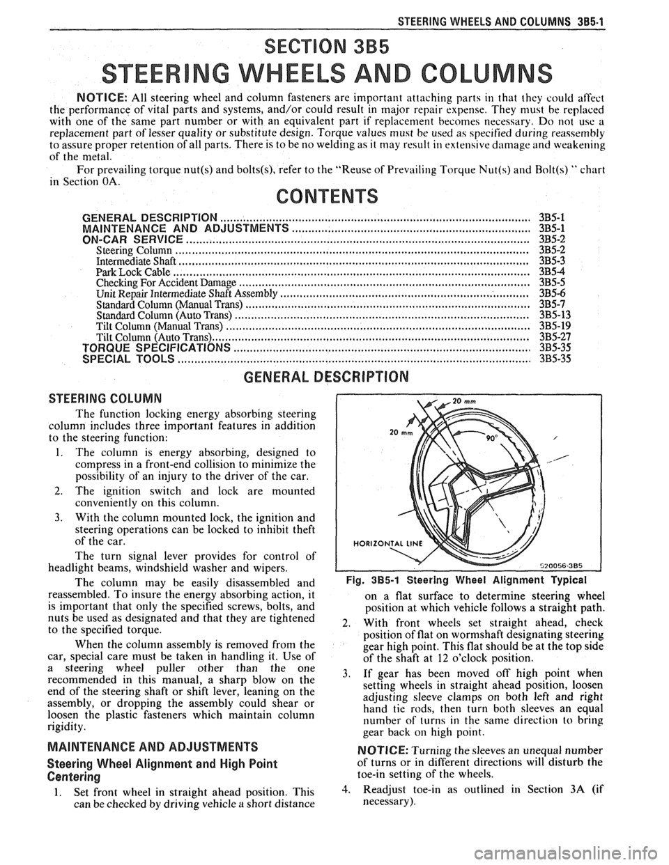
disassembled and Fig. 385-1 Steering Wheel Alignment ~ypical
reassembled. To insure the energy absorbing action, it
on a flat surface to determine steering wheel
is important that only the specified screws, bolts, and
position at which vehicle follows a straight path.
nuts be used as designated and that they are tightened
2. With front wheels set straight ahead, check to the specified torque.
position of flat on wormshaft designating steering
When the column assembly is removed from the
gear high point. This flat should be at the top side
car, special care must be taken in handling it. Use of
of the shaft at 12 o'clock position.
a steering puller other than the One 3, if gear has been moved off high when recommended in this manual, a sharp blow on the
setting wheels in straight ahead position, loosen
end of the steering shaft or shift lever, leaning on the
assembly, or dropping the assembly could shear or adjusting
sleeve clamps on both left and right
hand tie rods, then turn both sleeves an equal
loosen the plastic fasteners which maintain column
rigidity. number
of turns in the same direction
to bring
gear back
on high point.
MAINTENANCE AND ADJUSTMENTS NOTICE: Turning the sleeves an unequal number
Steering Wheel Alignment and High Point of turns or in different directions will disturb the
Centering toe-in setting of the wheels.
1. Set front wheel in straight ahead position, This 3. Readjust toe-in as outlined in Section 3A (if
can be checked by driving vehicle
a short distance necessary).