1988 PONTIAC FIERO open gas tank
[x] Cancel search: open gas tankPage 349 of 1825
6-4 ENGINE GENERAL INFORMATION
Bent connecting rod.
HEAVY KNOCK H0"FVVI"F TORQUE APPLIED
Broken balancer, or pulley hub. Replace parts as e Exhaust system grounded. Reposition as
necessary. necessary.
Loose torque converter bolts. Flywheel
cracked.
e Excessive main bearing clearance. Replace as
Accessory belts too tight or nicked. Replace
necessary.
and/or tension to specs as necessary.
e Excessive rod bearing clearance. Replace as
necessary.
LIGHT KNOCK HOT
Detonation or spark knock. Check operation of e Loose torque converter bolts.
EST or ESC (See Section
6D or 6E). Check e Exhaust leak at manifold. Tighten bolts and/or
engine timing and fuel quality.
replace gasket.
8 Excessive rod bearing clearance. Replace
bearings as necessary.
KNOCKS ON INITIAL START-UP BUT ONLY LASTS A FEW SECONDS
Noisy mechanical fuel pump. Replace pump.
When the engine is stopped, some valves
will be open. Spring pressure against lifters
Improper oil viscosity. Install proper oil viscosity will
tend to bleed lifter down. Attempts to
for expected temperatures. See Owner's Manual. repair
should be made only if the problem
is consistent.
Hydraulic lifter bleed down. Clean, test and @ Excessive crankshaft end clearance. Replace
replace as necessary. crankshaft
thrust bearing.
@ Excessive front main bearing clearance. Replace
worn parts.
KNOCKS AT IDLE HOT
Loose or worn drive belts. Tension and/or @ Excessive piston pin clearance. Ream and install
replace as necessary. oversize pins. (VIN R and 2) or replace piston
A/C Compressor or generator bearing. Replace and
pin.
as necessary.
e Connecting rod alignment. Check and replace
rods as necessary.
Noisy mechanical fuel pump. Replace pump.
8 Insufficient piston to bore clearance. Hone bore
Valve train. Replace parts as necessary. and
fit new piston.
@ Loose crankshaft balancer. Torque and/or
Improper oil viscosity. Install proper viscosity oil
replace worn parts.
for expected temperature4 See Owner" e Piston pin offset to wrong side. Install correct
ENGINE OVERHEATS
Coolant system leak, oil cooler system leak, or
2. Belt slipping or damaged. Replace tensioner, or
coolant recovery system not operating. Check for belt, as required.
leaks and correct as required. Check coolant
3. Thermostat stuck closed. Check and replace if
recovery tank, hose and radiator cap.
required.
4. Electrical cooling fan operation. See the
ELECTRICAL TROUBLESHOOTING
MANUAL.
5. Head gasket leaking. Check and repair as
required.
Page 419 of 1825
68-8 ENGINE COOLING
However, there are limits to the tensioner's ability to
The tensioner has rovisions for a visual check to
compensate for varying lengths of belts. With the
ten- verify that it is in t e "operating range" (see Figures
sioner outside of its operating range, poor tension
608 and 609). R
control andlor damage to the tensioner may result.
ALUMINUM RADIATOR REPAIR
This radiator utilizes an aluminum core with
plastic side tanks. The core and side tanks can be
replaced separately and core repair is easily made with
the hot melt adhesive method. A transaxle oil cooler
is located in one of the side tanks. The oil cooler can
be replaced. The drain cock is located on the lower part
of one of the tanks. The drain cock is also serviceable.
Core
The core is made of aluminum and is of the
crossflow design. It utilizes large tubes that resist
plugging, and repairs to the tubes and core are easily
made using the hot melt adhesive method.
The core is attached to the tanks by clinched tabs
on the core that can be bent back if tank or core
replacement is required.
If the damage to a tube is too severe, a tube can
be blocked or plugged as explained in "Tube Blocking.
" No more than two tubes should ever be blocked on
a core. Also replace the core if more than three tabs are
broken on one side, or if two adjacent tabs are broken.
Tanks
The tanks are attached to the core by the use of
clinched tabs. The clinched tabs can be bent back if the
tanks need to be removed from the core. Bend the tabs
back only enough to remove the tank. Overbending
will weaken the tabs.
A high temperature rubber gasket is used to seal
the mating surface between the core and the tank. (See
Fig. 8). The gasket must be replaced any time a tank
is removed from the core.
Transaxle Oil Cooler
The transaxle oil cooler is located in one of the
radiator side tanks. The oil cooler can be replaced by
removing the tank from the core.
A leaking oil cooler gasket can be replaced
without removing the tank from the core.
Drain Cock
The aluminum/plastic radiator utilizes a two
piece plastic drain cock and a rubber seal. The drain
cock is serviceable (See Fig.
9).
ALUMINUM RADIATOR SERVICE
The aluminum-plastic radiator can be repaired at
the dealership. The following components are easily
replaced:
e Core
e Tanks and gaskets
o Oil coolers and gaskets
e Drain cock and gasket The
tanks cannot be repaired if broken or
cracked. The radiator core can be replaced and the new
core used with the original tanks and oil cooler.
Precautions
As with all cooling system service, take measures
to prevent personal injury and damage to the system.
CAUTION: To help avoid the danger of
being burned, do not remove the
radiator cap while the engine and
radiator are
still hot. Scalding fluid
and steam can be blown out under
pressure if the
cap is taken off too
soon.
NOTICE: DO NOT USE "BOIL OUT" TANKS
OR VATS. Common service methods may
actually destroy an aluminum radiator. Caustic or
lye cleaning solutions must NOT be used for
aluminum radiators.
e Do not open the hood if you can see, or hear,
steam or coolant escaping from the engine
compartment.
e Do not remove radiator cap if radiator feels
warm.
e Do not remove the radiator cap or coolant
recovery tank cap if the coolant in the recovery
tank looks like it is boiling.
Wear eye protection.
e Wear gloves to protect your hands against
excessive heat, or the effects of chemicals on your
skin.
o Prevent dirt and water from entering the
transmission oil cooler.
e Do not use boil-out tanks, or vats, or other tanks
that have been used for copper and brass
radiators. The flux, acid, and caustic cleaners
remaining in these tanks will attack the
aluminum and cause radiator failure.
A separate
test tank containing clean water is strongly
recommended for servicing aluminum-plastic
radiators.
RIOTICE: Never use shop air that is not regulated
at
20 psi (138 kPa) to pressure test radiator.
Pressures over
20 psi (138 kPa) will damage the
radiator.
DIAGNOSIS
Leak Testing
Some core leaks can be detected by merely adding
water to the radiator. It is helpful to clean the core so
that the damaged area can be more easily found.
Page 422 of 1825
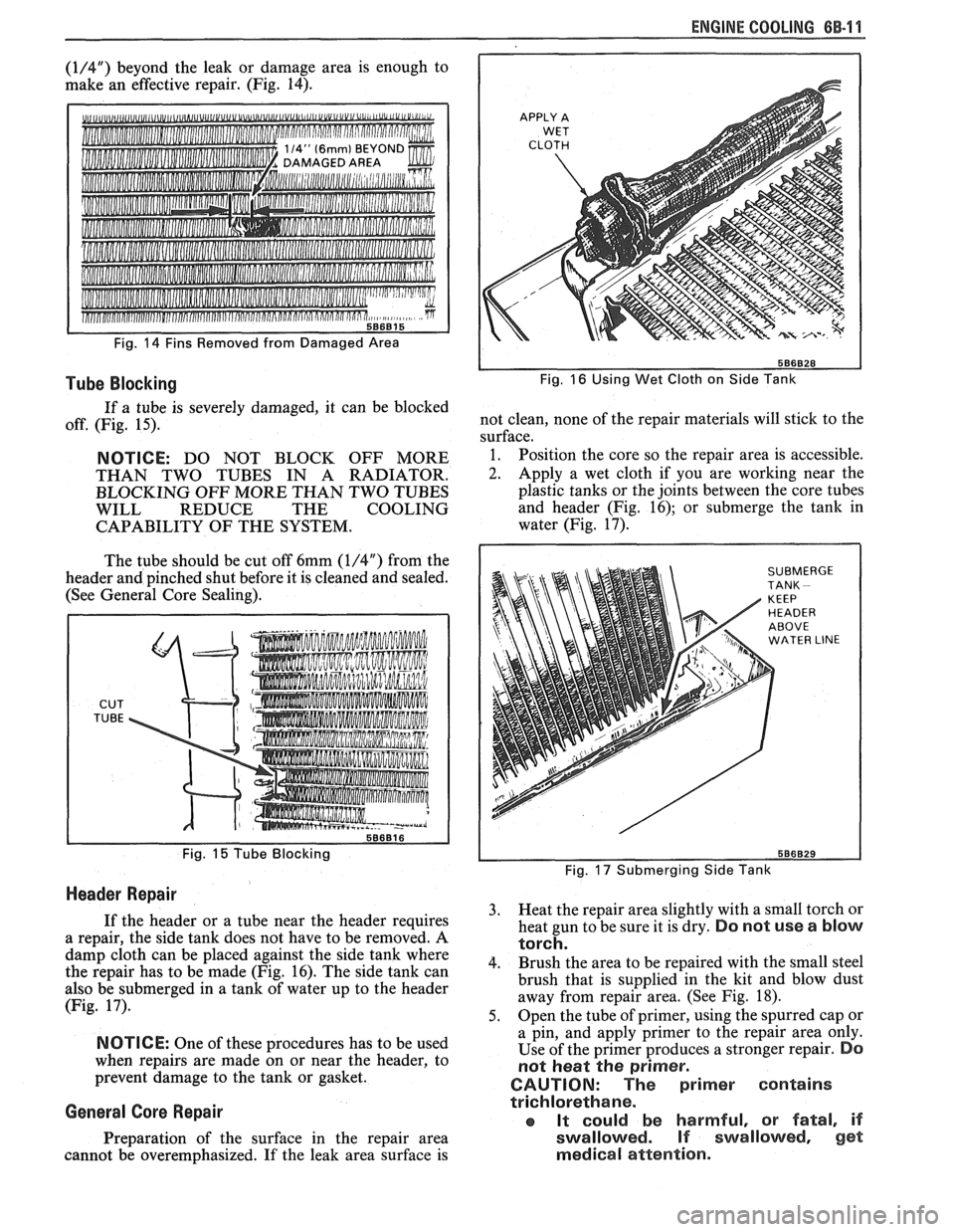
(1/4") beyond the leak or damage area is enough to
make an effective repair. (Fig. 14).
d""U,"
Fig. 14 Fins Removed from Damaged Area
Tube Blocking
If a tube is severely damaged, it can be blocked
off. (Fig. 15).
NOTICE: DO NOT BLOCK OFF MORE
THAN TWO TUBES IN A RADIATOR.
BLOCKING OFF MORE THAN TWO TUBES
WILL REDUCE THE COOLING
CAPABILITY OF THE SYSTEM.
The tube should be cut off 6mm
(1/4") from the
header and pinched shut before it is cleaned and sealed.
(See General Core Sealing).
CUT
TUBE
Fig. 15 Tube Blocking
Header Repair
If the header or a tube near the header requires
a repair, the side tank does not have to be removed.
A
damp cloth can be placed against the side tank where
the repair has to be made (Fig. 16). The side tank can
also be submerged in a tank of water up to the header
(Fig. 17).
NOTICE: One of these procedures has to be used
when repairs are made on or near the header, to
prevent damage to the tank or gasket.
General Gore Repair
Preparation of the surface in the repair area
cannot be overemphasized. If the leak area surface is
ENGINE COOLING 6B-11
Fig. 16 Using Wet Cloth on Side Tank
not clean, none of the repair materials will stick to the
surface.
1. Position the core so the repair area is accessible.
2. Apply a wet cloth if you are working near the
plastic tanks or the joints between the core tubes
and header (Fig. 16); or submerge the tank in
water (Fig. 17).
SUBMERGE TANK -
Fig. 17 Submerging Side Tank
3. Heat the repair area slightly with a small torch or
heat gun to be sure it is dry.
Do not use a blow
torch.
4. Brush
the area to be repaired with the small steel
brush that is supplied in the kit and blow dust
away from repair area. (See Fig. 18).
5. Open
the tube of primer, using the spurred cap or
a pin, and apply primer to the repair area only.
Use of the primer produces a stronger repair.
Do
not heat the primer.
CAUTION: The primer contains
trichlorethane.
aa It could be harmful, or fatal, if
swallowed. If swaIIowed, gel
medical attention.
Page 423 of 1825
88-12 ENGINE COOLING
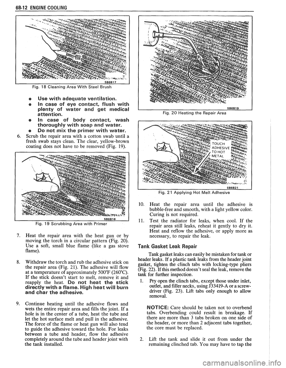
Fig. 18 Cleaning Area With Steel Brush
e Use with adequate ventilation.
In case of eye contact, flush with
plenty of water and get medical
attention.
In case of body
contact, wash
thoroughly with soap
and water.
Do not
mix the primer with water.
6. Scrub the repair area with a cotton swab until a
fresh swab stays clean. The clear, yellow-brown
coating does not have to be removed (Fig. 19).
Fig. 19 Scrubbing Area with Primer
7. Heat the repair area with the heat gun or by
moving the torch in a circular pattern (Fig. 20).
Use a soft, small blue flame (like a gas stove
flame).
8. Withdraw the torch and rub the adhesive stick on
the repair area (Fig. 21). The adhesive will flow
at a temperature of approximately 500°F (260°C).
If the stick doesn't start to melt, remove it and
reapply the heat.
Do not heat the stick
directly with
a flame. High heat will burn
and
char the adhesive.
9. Continue heating until the adhesive flows and
wets the entire repair area and fills the joint. If a
hole is in the center of a tube, heat the tube and
let the hot surface melt and pull in the adhesive.
The force of the flame or heat gun will also tend
to guide the adhesive toward the hole. For leaks
between a tube and header, flow the adhesive
completely around the tube and header joint with
the tank installed.
Fig. 20 Heating the Repair Area
I
Fig. 21 Applying Hot Melt Adhesive I
10. Heat the repair area until the adhesive is
bubble-free and smooth, with a light yellow color.
Curing is not required.
11. Test the radiator for leaks, when cool. If the
repair area still leaks, reheat it gently to dry it.
Heat and
reflow the adhesive, or apply more as
necessary, to repair the leak.
Tank Gasket beak Repair I 1
Tank gasket leaks can easily be mistaken for tank or
header leaks. If a plastic tank leaks from the header joint
gasket, tighten the clinch tabs with locking-type pliers
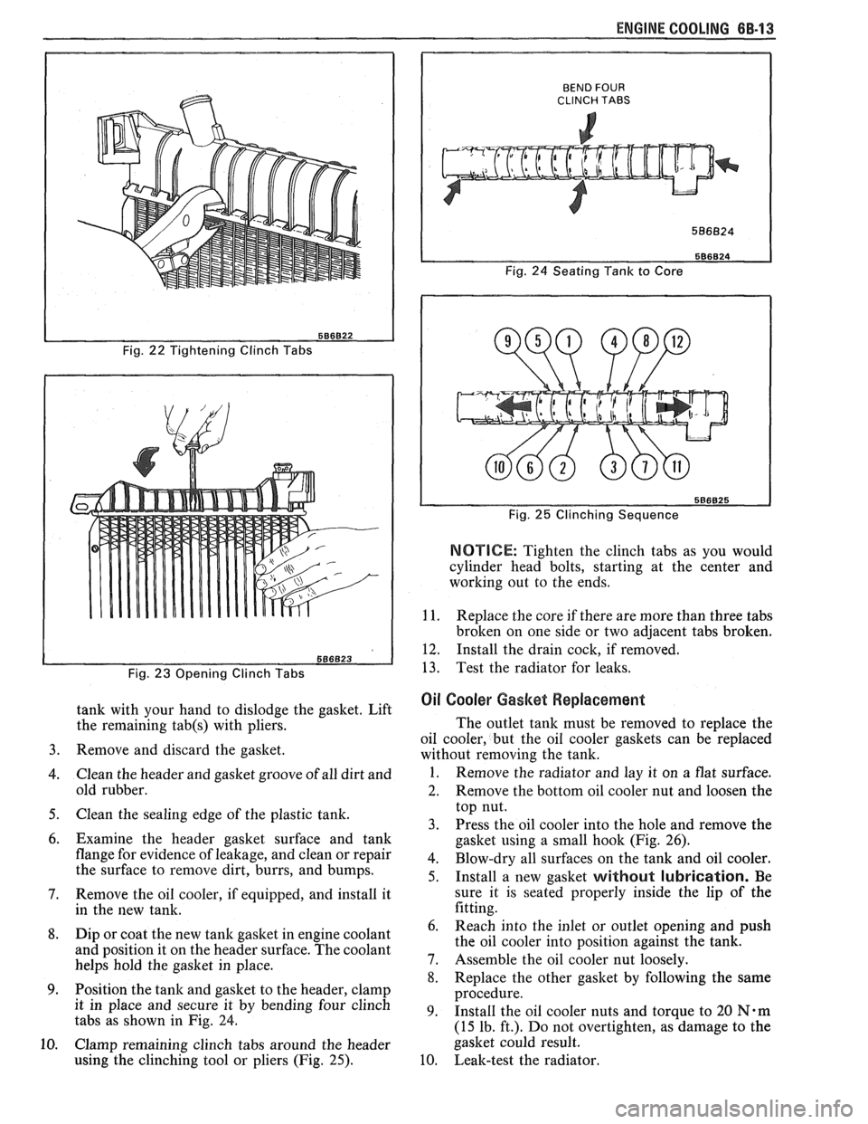
(Fig. 22). If this method doesn't seal the leak, remove the
tank for further inspection.
1. Pry open the clinch tabs, except those under inlet,
outlet, and filler necks, using
J33419-A or a screw-
driver (Fig.
23). Lift tabs only enough to allow
removal.
NOTICE: Care should be taken not to overbend
tabs. Overbending could result in breakage. If
there are more than
3 tabs broken on one side of
the header, or more than
2 adjacent tabs together,
the core must be replaced.
2. Lift the tank and slide it out from under the
remaining clinched tab. You may have to tap the
Page 424 of 1825
ENGINE COOLING 6B-13
Fig. 22 Tightening Clinch Tabs
Fig.
23 Opening Clinch Tabs
tank with your hand to dislodge the gasket. Lift
the remaining
tab(s) with pliers.
Remove and discard the gasket.
Clean the header and gasket groove of all dirt and
old rubber.
Clean the sealing edge of the plastic tank.
Examine the header gasket surface and tank
flange for evidence of leakage, and clean or repair
the surface to remove dirt, burrs, and bumps.
Remove the oil cooler, if equipped, and install it
in the new tank.
Dip or coat the new
tank gasket in engine coolant
and position it on the header surface. The coolant
helps hold the gasket in place.
Position the tank and gasket to the header, clamp
it in place and secure it by bending four clinch
tabs as shown
in Fig. 24.
Clamp remaining clinch tabs around the header
using the clinching tool or pliers (Fig.
25).
BEND FOUR CLINCH TABS
Fig. 24 Seating Tank to Core
Fig.
25 Clinching Sequence
NOTICE: Tighten the clinch tabs as you would
cylinder head bolts, starting at the center and
working out to the ends.
1 1. Replace the core if there are more than three tabs
broken on one side or two adjacent tabs broken.
12. Install the drain cock, if removed.
13. Test the radiator for leaks.
Oil Cooler Gasket Replacement
The outlet tank must be removed to replace the
oil cooler, but the oil cooler gaskets can be replaced
without removing the tank.
1. Remove the radiator and lay it on a flat surface.
2. Remove the bottom oil cooler nut and loosen the
top nut.
3. Press the oil cooler into the hole and remove the
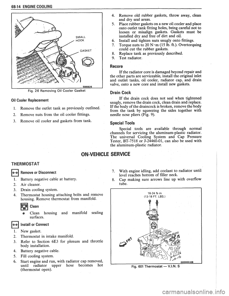
gasket using a small hook (Fig. 26).
4. Blow-dry all surfaces on the tank and oil cooler.
5. Install a new gasket without lubrication. Be
sure it is seated properly inside the lip of the
fitting.
Reach into the inlet or outlet opening and push
the oil cooler into position against the tank.
Assemble the oil cooler nut loosely.
Replace the other gasket by following the same
procedure.
Install the oil cooler nuts and torque to
20 N.m
(15 lb. ft.). Do not overtighten, as damage to the
gasket could result.
Leak-test the radiator.
Page 425 of 1825
6B-I4 ENGINE COOLING
SMALL
586826
Fig. 26 Removing Oil Cooler Gasket
4. Remove old rubber gaskets, throw away, clean
and dry seal areas.
5. Place rubber gaskets on a new oil cooler and place
onto outlet tank fitting holes, being careful not to
loosen or misalign gaskets. Gaskets must be
installed dry and free of dirt and oil.
6. Install
and tighten nuts snugly onto fittings.
7. Torque nuts
to 20
N.m (15 lb. ft.). Overtorquing
could cut the rubber gaskets.
8. Replace
tank as previously described.
9. Test radiator.
Recore
If the radiator core is damaged beyond repair and
the other parts are serviceable, install the original inlet
and outlet tanks, oil cooler, radiator cap, and drain
valve, onto a new core and install new gaskets.
Drain Cock
Oil Cooler Replacement If the drain cock does not seal when tightened
snugly, remove the drain cock, clean drain and replace.
1. Remove
the outlet tank as previously outlined. If
the body of the draincock is broken, remove the body
from the tank by squeezing the sides together with
2. Remove nuts from the oil cooler fittings.
needle nose pliers (Fig. 9).
Remove oil cooler and gaskets from tank. Special Tools
Special tools are available through normal
channels for servicing the aluminum-plastic radiator.
The universal Cooling System and Cap Pressure
Tester, BT-7518 or J-24460-01, can also be used with
the aluminum-plastic radiator.
ON-VEHICLE SERVICE
THERMOSTAT
Remove or Disconnect
1. Battery negative cable at battery.
2. Air cleaner.
3. Drain cooling system.
4. Thermostat housing attaching bolts and remove
housing. Remove thermostat from manifold.
Clean
Clean housing and manifold sealing
surfaces.
Install or Connect
1. New gasket.
2. Thermostat in intake manifold.
3. Refer
to Section 6E3 for plenum and throttle
body installation.
4. Battery negative cable.
5. Fill cooling system.
6. Start engine and run, with radiator cap removed,
until radiator upper hose becomes hot
(thermostat open). 7.
With
engine idling, add coolant to radiator until
level reaches bottom of filler neck.
8. Cap making sure arrows line up with overflow
tube.
18-24 N,m (13-18 FT. LBS.)
Fig. 601 Thermostat - V.I.N. S
Page 434 of 1825
ENGINE FUEL 6C.3
a Fuel feed and return pipes are secured to the
underbody with clamps and screw assemblies.
The pipes should be inspected occasionally for
leaks, kinks or dents.
e Follow the same routing as the original pipe.
e Pipes must be properly secured to the frame to
prevent chafing. A minimum of 6 mm
(1/4")
clearance must be maintained around a pipe to
prevent contact and chafing.
MPFl Fuel Pipes
Due to the fact that fuel pipes are under high
pressure, these systems require special consideration for service.
Many feed and return pipes use screw couplings
with
"0" Rings. Any time these fittings are loosened
to service or replace components, ensure that:
a A backup wrench is used while loosening and
tightening the fitting.
e Check all "0" rings at fitting locations (if
applicable) for cuts or any damage and replace
any that appear worn or damaged.
e Use correct torque when tightening fittings.
If pipes are replaced always use original
equipment parts, or parts that meet GM
specifications.
Fuel and Vapor Hoses
NOTICE: Fuel and vapor hoses are specially
manufactured. If replacement becomes necessary,
it is important to use only replacement hoses
meeting GM Specification 6163-M. These hoses
are identified with the words "Fluoroelastomer"
on them. Hoses not so marked could cause early
failure, or fail to meet emission standards.
e Do not use rubber hose within 4" of any part of
the exhaust system, or within
10" of the catalytic
converter.
FUEL PUMP
The electric fuel pump is in the fuel tank. The
tank has an outlet for a vapor return system. Any vapor
which forms is returned to the fuel tank along with hot
fuel through a separate line. This greatly reduces any
possibility of vapor lock by keeping cool fuel from the
tank constantly circulating through the fuel pump.
FUEL PUMP RELAY
To control fuel pump operation, a fuel pump
relay is used.
When the ignition switch is turned to "RUN"
position, the fuel pump relay activates the electric fuel
pump for
1.5 to 2.0 seconds to prime the injector(s). If
the ECM does not receive reference pulses from the
distributor after this time, the ECM signals the relay
to turn off the fuel pump. The relay will once again
activate the fuel pump when the
ECM receives
distributor reference pulses.
Fuel Filter
CAUTION: To reduce the risk of fire
and personal injury, it is necessary
to
relieve the fuel system pressure
before servicing fuel system
components. (See Fuel System
Pressure Relief.)
The inline filters can be found on the rear
crossmember of the vehicle. Always use a backup
wrench any time that the fuel filter is removed or
installed. Also make sure that a good
"0" Ring is used
at all screw couple locations. Torque on fittings is
30
N-m (22 lb. ft.).
FUEL TANK
The fuel tank is usually located under the rear of
the vehicle and a number of shapes and sizes are used
depending on the application.
The tank is held in place by two metal straps,
hinged (with a bolt through the hinge) and secured at
the opposite end with a nut and bolt assembly.
Anti-squeak pieces are used on top of the tank to
reduce rattles and other annoying noises.
The fuel tank, cap and lines should be inspected
for road damage, whch could cause leakage. Inspect
fuel cap for correct sealing and indications of physical
damage. Replace any damaged or malfunctioning
parts.
Before attempting service of any type on the fuel
tank, always
(1) remove negative battery cable from
battery, (2) place "no smoking" signs near work areas,
(3) be sure to have C02 fire extinguisher handy, (4)
wear safety glasses and
(5) siphon or pump fuel into an
explosion proof container.
Fuel Filler Gap
The fuel tank filler neck is equipped with a
screw-type cap. The threaded part of the cap requires
several turns counterclockwise to remove. The long
threaded area is designed to allow any remaining fuel
tank pressure to escape while the cap is being removed.
A built-in torque-limiting device prevents
overtightening. To install, turn the cap clockwise until
a clicking noise is heard. This signals that the correct
torque has been reached and the cap is fully seated.
N OTI G E: If a fuel filler cap requires replacement,
use only a cap with the same features. Failure to
use the correct cap can result in a serious
malfunction of the system.
Available on some models is an electric locking
fuel filler cap. Information on this option will be found
in Section
9E.
FUEL TANK FILLER NECK
To help prevent refueling with leaded gasoline,
the fuel filler neck on gasoline engine cars has a built-in
restrictor and deflector. The opening in the restrictor
will only admit the smaller unleaded gas nozzle spout,
which must be fully inserted to bypass the deflector.
Attempted refueling with a leaded gas nozzle or failure
Page 436 of 1825
ENGINE FUEL CC-5
FUEL TANK
Draining Fuel Tank
1. Disconnect the negative battery cable. Also have
a dry chemical (Class B) fire extinguisher near the
work area.
2. Use a hand operated pump device when possible
to drain as much fuel through the filler tube as
possible.
3. If
a hand operated pump device cannot be used
to complete the draining process, use a siphon at
the main (not return) fuel pipe at the fuel pump
or the fuel tank gage unit.
CAUTION: Never drain or store
gasoline in an open container due to
the possibility of fire or explosion.
4. Reinstall any removed hoses, lines and cap.
Removing Fuel Tank
1. Remove all fuel, see "Draining Fuel Tank".
2. Support
fuel tank and disconnect the two fuel
tank retaining straps.
3. Lower tank enough to disconnect sending unit
wire, hoses, and ground strap, if so equipped.
4. Remove tank from vehicle.
5. Remove sending unit.
Installing Fuel Tank
1. Reverse removal procedure.
2. Always replace "0" ring when tank unit has been
removed.
3. When reinstalling fuel tank, be sure to reinstall
anti-squeak pieces on top of the tank to reduce
rattles and other annoying noises.
4. Tighten fuel tank retaining strap bolts or screws.
Fuel System Cleaning
CAUTION: This procedure will NOT
remove all fuel vapor. Do not attempt
any repair
on tank or filler neck where
heat or flame is required, as an
explosion resulting in personal injury
could occur.
If trouble is due to contaminated fuel or foreign
material that is in the tank, it can usually be cleaned.
If tank is rusted internally, it should be replaced.
1. Disconnect negative battery cable.
2. Disconnect ignition engine harness connector.
Have dry chemical (Class B) fire extinguisher
near the work area.
3. Relieve fuel system pressure.
4. Drain fuel tank (see "Draining Fuel Tank").
5. Remove fuel tank (see "Fuel Tank Removal").
6. Remove external fuel filter and inspect for
contamination. If filter is plugged, replace.
7. Locate tank away from heat, flame, or other
source of ignition. Remove fuel gage sending unit
and fuel pump assembly, if so equipped, and
inspect condition of strainer. If strainer is
contaminated, a new strainer should be installed.
8. Complete draining of tank by rocking it and
allowing fuel to run out of fuel sending unit
opening.
9. Flush fuel tank with running hot water for at least
five minutes. Pour water out of fuel sending unit
opening. (Rock tank to be sure that removal of
water is complete.)
10. Disconnect fuel feed pipe and use air pressure to
clean fuel line. Apply air pressure in the opposite
direction fuel normally flows through the line. On
vehicles equipped with a fuel return line, clean
line in similar manner. Disconnect pipe at
throttle body unit and apply air pressure to clean
return line. Reconnect and torque all pipes to 30
N-m (22 1b. ft.).
11. Use low air pressure to clean pipes on fuel gage
sending unit.
112. Install new strainer on fuel gage sending unit, if
required. Install fuel gage sending unit and fuel
pump, with new gasket, into tank and install fuel
tank. Connect fuel gage wire harness to body
harness. Connect all fuel lines except feed line to
external fuel filter.
13. Disconnect fuel feed hose to chassis pipe at front.
Connect a hose to front end of chassis fuel feed
pipe and insert other end of hose into a one gallon
fuel can.
14. Connect battery cable.
15. Put six gallons of clean fuel into fuel tank and
apply 12 volts to Terminal
"G" of ALCL to
operate fuel pump. Pump two quarts of fuel into
fuel can. This will purge fuel pump.
16. Remove hose and connect fuel hose to chassis
pipe.
17. Check all connections
for leaks; tighten all hose
clamps.
Fuel Tank Purging Procedure
The following procedure is used prior to repairing
of fuel tank.
1. Remove fuel sending unit and fuel pump and
drain all remaining fuel from tank.
2. Visually inspect interior cavity of tank. If any fuel
is evident, drain again.
3. Move tank to flushing area (wash rack).
4. Fill tank completely with tap water, agitate
vigorously and drain.
5. Add gasoline emulsifying agent to the tank, refill
with water, agitate mixture for 10 minutes, and
drain tank completely.
For correct gasoline emulsifying agent-to-water
mixture, refer to the
manufacturer's
specifications. Use an available emulsifying
agent, such as "Product-Sol No.
913", or
equivalent.
6. When empty, refill the tank to overflowing with
water. Completely flush out remaining mixture
and empty tank.
7. If available, an explosion meter should be used Lo
check for negative reading.
8. Perform required service work.