1988 PONTIAC FIERO water pump
[x] Cancel search: water pumpPage 21 of 1825
OB-4 MAINTENANCE AND LUBRICATION
Tire and wheel operation - Be alert to a vibra-
tion of the steering wheel or seat at normal highway
speeds. This may mean a wheel balance is needed. Also, a
pull right or left on a straight, level road may show the
need for
a tire pressure adjustment or wheel alignment.
Steering system operation - Be alert to
changes in steering action. An inspection is needed when
the steering wheel is harder to turn or has too much free
play or if unusual sounds are noted when turning or
parking.
Headlight aim operation - Take note of light
pattern occasionally. If beam aim doesn't look right,
headlights should be adjusted.
AT EACH FUEL FILL
Engine oil level check - Check engine oil level
and add if necessary. See your Owner's
Manual for further
details.
NOTICE: A large loss in this system may indicate a
problem. Have it inspected and repaired at once.
Engine coolant level and condition - Check
engine coolant level in coolant reservoir tank and add if
necessary. Replace if dirty or rusty. See your Owner's
Manual for further details.
NOTICE: A large loss in this system may indicate a
problem. Have it inspected and repaired at once.
Windshield washer fluid level check -- Check
washer fluid level in container and add if necessary.
Hood latch operation - When opening hood on
cars equipped with hoods that open from the front, note
the operation of secondary latch. It should keep hood from
opening all the way when primary latch is released. Make
sure that hood closes firmly.
AT LEAST MONTI-ILY
Tire and wheel inspection and pressure
check--
Check tires for abnormal wear or damage. Also,
check for damaged wheels. Keep pressures as shown on
Tire Placard on the driver's door (include spare unless it is
a stowaway). Pressure should b\: checked when tires are
"cold". See "Tires" in Owner's Manual for further
infomation.
Light operation check - Check operation of
license plate light, side-marker lights, headlights includ-
ing high beams, parking lights, taillights, brake lights.
turn signals, backup lights, instrument panel and interior
lights and hazard warning flashers.
Fluid leak check - After the car has been parked
for a while, inspect the surface beneath the car for water,
oil, fuel or other fluids. Water dripping from the air
conditioning system after use is normal. If you notice fuel
leaks or fumes, the cause should be found and corrected at
once.
AT LEAST TWICE A YEAR (FOR EXAMPLE,
EVERY SPRING AND FALL)
Power steering pump fluid level check --
Check power steering pump fluid level in accordance with
Owner's Manual instructions and keep at proper level.
NOTICE: A large loss in this system may indicate a
problem. Have it inspected and repaired at once.
Brake master cylinder reservoir fluid level
check ---- Check fluid and keep at proper level. Note: It is
normal for the brake fluid level to go down slightly as the
brake pads wear
- so be sure to keep reservoir filled.
NOTICE: A large loss in this system may indicate a
problem. Have
it inspected and repaired at once.
Clutch system service --- manual transmis-
sionltransaxle --- For cars equipped with hydraulic
clutch system, check the reservoir fluid level and add fluid
as required. All others, check clutch pedal free travel and
adjust as necessary. See your Owner's Manual for further
details.
~
NOTICE: A large loss in this system may indicate a
problem. Have it inspected and repaired at once.
Weatherstrip Lubrication - Clean surface and
then apply a thin film of silicone grease with a clean cloth.
EACH TIME OIL IS CHANGED
Automatic and manual transmissionltrans-
axle fluid level check - Check transmission/transaxle
fluid level and add as required. (Corvette only) if equipped
with manual transmission
- check fluid in the overdrive
unit and add as required.
NOTICE: A large loss in this system may indicate a
problem. Have
it inspected and repaired at once.
Brake systems inspection - For convenience,
the following should be done when wheels are removed
for rotation: Inspect lines and hoses for proper hookup,
binding, leaks, cracks, chafing, etc. Inspect disc brake
pads for wear and rotors for surface condition. Also in-
spect drum brake linings for wear and cracks. Inspect
other brake parts, including drums, wheel cylinders, park-
ing brake, etc. at the same time. Check parking brake
adjustment.
INSPECT BRAKES MORE OFTEN IF DRIVING
HABITS OR CONDITIONS RESULT IN FREQUENT
BRAKING.
Steering, suspension and front drive axle
boot and seal inspection
- Inspect front and rear
suspension and steering system for damaged, loose or
missing parts, signs of wear or lack of lubrication. Inspect
power steering lines and hoses for proper hookup, bind-
ing, leaks, cracks, chafing, etc. (On cars equipped with
manual steering gear, check for seal leakage.) On
front-
wheel-drive cars, clean then inspect drive axle boot seals
for damage, tears or leakage. Replace seals if necessary.
Exhaust system inspection - Inspect complete
system. Inspect body near the exhaust system. Look for
broken, damaged, missing or out-of-position parts as well
as open seams, holes, loose connections or other condi-
tions which could cause a heat buildup in the tloor pan or
could let exhaust fumes seep into the trunk or passenger
compartment.
Page 69 of 1825
1B-26 AIR CONDITIONING
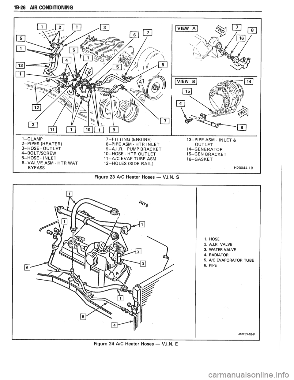
7-FITTING (ENGINE)
13-PIPE ASM - INLET & 8-PIPE ASM - HTR INLET
OUTLET
9-A.I.R. PUMP BRACKET 14-GENERATOR
10-HOSE
- HTR OUTLET
15-GEN BRACKET 11-AIC EVAP TUBE ASM 16-GASKET
12-HOLES (SIDE RAIL)
Figure 23 NC Heater Hoses - V.I.N. S
2. A.I.R. VALVE
3. WATER VALVE
4. RADIATOR
5. AIC EVAPORATOR TUBE
Figure 24 NC Heater Hoses - V.I.N. E
Page 346 of 1825
ENGINE GENERAL INFORMATION 6-1
SECTION 6
NE GENERAL NFORMAT
Description ............................................................... 6 TBI ...................................... .. ...... 6E2 ................ Engine Mechanical Multi Port Fuel Injection (MPFI) 6E3 -
............................................... 2.8L V-6 ....................................................... 6A2 Exhaust Systems 6F
5.OL V-8 ......................................................... 6A3 ~~~~~~l ~~f~~~~ti~~ ..................................... 6-2
............................ Engine Cooling ...................................................... 6B Engine Performance Diagnosis 6-3 ............................. Engine Fuel 6C Engine Mechanical Diagnosis
6-3 ........................................................... ................................... Engine Knock Diagnosis 6-4
Engine Electrical ................................................... 6D Compression Test ...................................... ... 6-5
................... Driveability and Emission Controls ...................... 6E Oil Leak Detection .. ..................... 6-5
ALL NEW GENERAL MOTORS VEHICLES ARE CERTIFIED BY THE UNITED STATES
ENVIRONMENTAL PROTECTION AGENCY AS CONFORMING TO THE REQUIREMENTS OF
THE REGULATIONS FOR THE CONTROL OF AIR POLLUTION FROM NEW MOTOR VEHICLES.
THlS CERTIFICATION IS CONTINGENT ON CERTAIN ADJUSTMENTS BEING SET TO
FACTORY STANDARDS. IN MOST CASES, THESE ADJUSTMENT POINTS EITHER HAVE
BEEN PERMANENTLY SEALED AND/OR MADE INACCESSIBLE TO PREVENT
INDISCRIMINATE OR ROUTINE ADJUSTMENT IN THE FIELD. FOR
THlS REASON, THE
FACTORY PROCEDURE FOR TEMPORARILY REMOVING PLUGS, CAPS, ETC., FOR
PURPOSES OF SERVICING THE PRODUCT MUST BE STRICTLY FOLLOWED AND,
WHEREVER PRACTICABLE, RETURNED TO THE ORIGINAL INTENT OF THE DESIGN.
DESCRIPTION OF: SECTION 6
SECTION 6A - ENGINE MECHANICAL used for each carburetor. TBI units are described in
This section general contains information on the Section 6E.
mechanical parts of the engine, such as block,
crankshaft, pistons, valve train, and camshaft, that are
common to most engines. Overhaul procedures,
removal and replacement procedures, and
s~ecifications are also covered. Subsections furnish
detailed information on each specific engine. Service
SECTION 6D - ENG l N E ELECTRICAL
information is also given that relates to that engine's
use in each
Carline. Specific subsections are: Items
covered in this section are battery,
generator, starter, primary and secondary ignition,
6A2
- 2.8L V-6 Engine
engine wire harness, spark plugs and wires, and
6A3
- 5.OL V-8 Engine
ignition switch.
SECTION 6B - ENGINE COOLING
Engine cooling system components such as
radiator, water pump, thermostat, and cooling fan, are
covered in this section. Accessory drive belts are also
covered, along with cooling system capacities.
SECTION 6C - FUEL SYSTEM
This section contains information on all the parts
of the fuel system
except the carburetor, or Throttle
Body Injection unit (TBI) itself. Items covered are fuel
tank, fuel pump, and fuel lines. Specific subsections are
SECTION 6E - DRIVEABILITY AND EMISSIONS
This section covers emission control systems
general information, and diagnostic procedures which
will lead to repairing performance and driveability
related problems for gasoline engine equipped vehicles.
All emission components are covered, as well as all
removal and replacement procedures. Instructions on
use of special tools are also given. Specific sections are:
6E
- Driveability and Emissions
6E2
- Fuel Injection (TBI)
Page 366 of 1825
2.8 LITER V.6 6A2-15
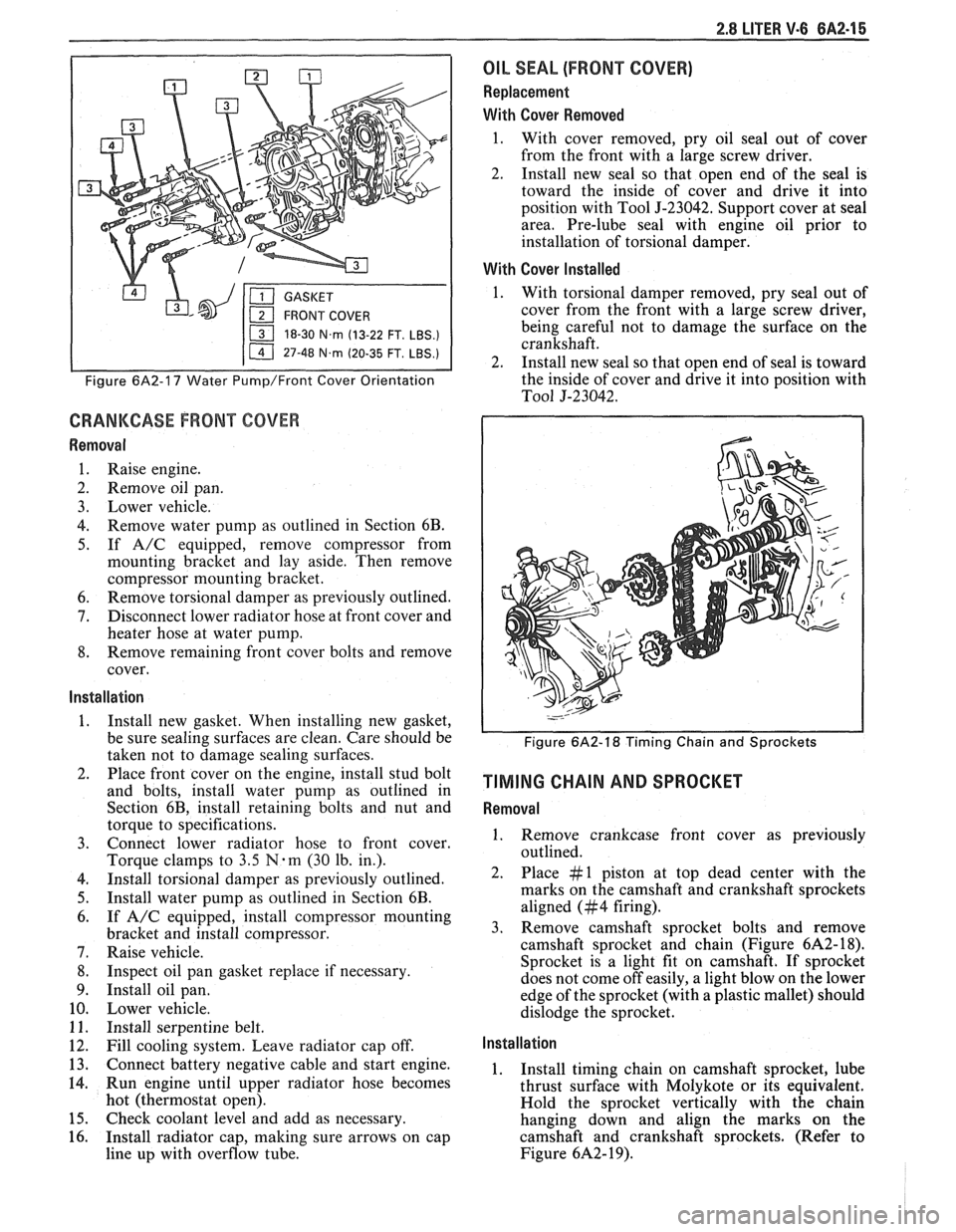
18-30 N.m (13-22 FT. LBS.)
I 11 47-48 N.m (20-35 FT. LBS.) I
Figure 6A2-17 Water Pump/Front Cover Orientation
CRANKCASE FRONT COVER
Removal
1. Raise engine.
2. Remove oil pan.
3. Lower vehicle.
4. Remove water pump as outlined in Section 6B.
5. If A/C equipped, remove compressor from
mounting bracket and lay aside. Then remove
compressor mounting bracket.
6. Remove torsional damper as previously outlined.
7. Disconnect lower radiator hose at front cover and
heater hose at water pump.
8. Remove remaining front cover bolts and remove
cover.
Installation
1. Install new gasket. When installing new gasket,
be sure sealing surfaces are clean. Care should be
taken not to damage sealing surfaces.
2. Place front cover on the engine, install stud bolt
and bolts, install water pump as outlined in
Section 6B, install retaining bolts and nut and
torque to specifications.
3. Connect lower radiator hose to front cover.
Torque clamps to
3.5 N-m (30 lb. in.).
4. Install torsional damper as previously outlined.
5. Install water pump as outlined in Section 6B.
6. If A/C equipped, install compressor mounting
bracket and install compressor.
7. Raise vehicle.
8. Inspect oil pan gasket replace if necessary.
9. Install oil pan.
10. Lower vehicle.
11. Install serpentine belt.
12. Fill cooling system. Leave radiator cap off.
13. Connect battery negative cable and start engine.
14. Run engine until upper radiator hose becomes
hot (thermostat open).
15. Check coolant level and add as necessary.
16. Install radiator cap, making sure arrows on cap
line up with overflow tube.
OIL SEAL (FRONT COVER)
Replacement
With Cover Removed
1. With cover removed, pry oil seal out of cover
from the front with a large screw driver.
2. Install new seal so that open end of the seal is
toward the inside of cover and drive it into
position with Tool
5-23042. Support cover at seal
area. Pre-lube seal with engine oil prior to
installation of torsional damper.
With Cover Installed
1. With torsional damper removed, pry seal out of
cover from the front with a large screw driver,
being careful not to damage the surface on the
crankshaft.
2. Install new seal so that open end of seal is toward
the inside of cover and drive it into position with
To01 5-23042.
Figure 6A2-18 Timing Chain and Sprockets
TIMING CHAIN AND SPROCKET
Removal
1. Remove crankcase front cover as previously
outlined.
2. Place #1 piston at top dead center with the
marks on the camshaft and crankshaft sprockets
aligned (#4 firing).
3. Remove camshaft sprocket bolts and remove
camshaft sprocket and chain (Figure
6A2- 18).
Sprocket is a light fit on camshaft.
If sprocket
does not come off easily, a light blow on the lower
edge of the sprocket (with a plastic mallet) should
dislodge the sprocket.
Installation
1. Install timing chain on camshaft sprocket, lube
thrust surface with Molykote or its equivalent.
Hold the sprocket vertically with the chain
hanging down and align the marks on the
camshaft and crankshaft sprockets. (Refer to
Figure
6A2- 19).
Page 377 of 1825
6A2-26 2.8 LITER V-6
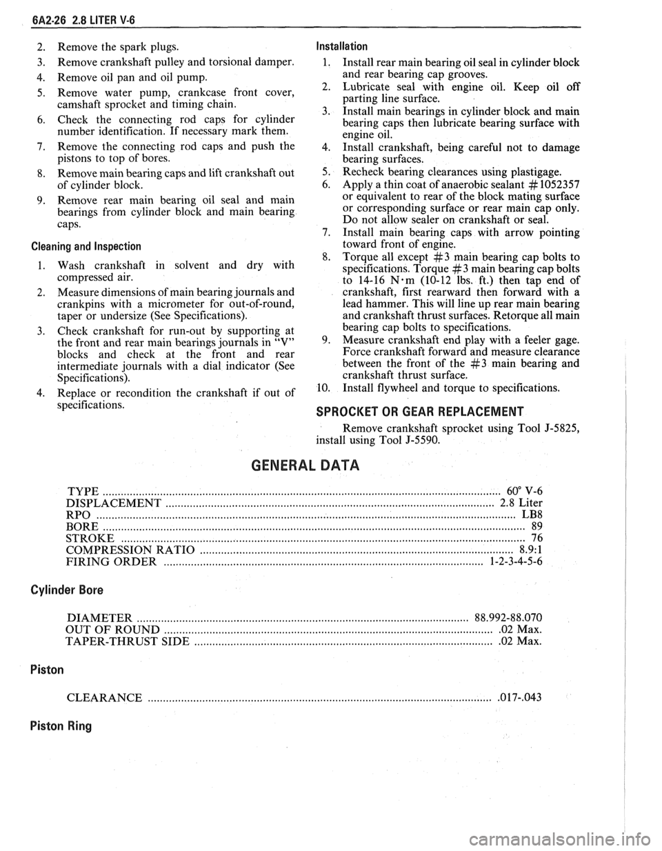
2. Remove the spark plugs. Installation
3. Remove
crankshaft pulley and torsional damper. 1. Install rear main bearing oil seal in cylinder block
4. Remove oil pan and oil pump. and
rear bearing cap grooves.
5. Remove water pump, crankcase front cover, 2. Lubricate seal with engine oil. Keep oil off
camshaft sprocket and timing chain. parting
line surface.
3. Install main bearings in cylinder block and main
6. Check the connecting rod caps for cylinder
bearing caps then lubricate bearing surface with
number identification. If necessary mark them.
engine oil.
7. Remove the connecting rod caps and
push the
4. 1n;tall crankshaft, being careful not to damage
pistons to top of bores.
bearing surfaces.
8. Remove main bearing caps and lift crankshaft out 5. Recheck bearing clearances using plastigage.
of cylinder block. 6.
Apply a thin coat of anaerobic sealant
# 1052357
9. Remove rear
main bearing oil seal and main or
equivalent to rear of the block mating surface
bearings from cylinder block and main bearing or corresponding
surface or rear main cap only.
caps. Do
not allow sealer on crankshaft or seal.
7. Install main bearing caps with arrow pointing
Cleaning and Inspection toward front of engine.
8. Torque all except
#3 main bearing cap bolts to
1. Wash crankshaft in solvent and dry with
specifications. Torque
#3 main bearing cap bolts
compressed air. to 14-16
N-m (10-12 lbs. ft.) then tap end of
2. Measure
dimensions of main bearing journals and crankshaft, first rearward then forward with a
crankpins with a micrometer for out-of-round, lead
hammer. This will line up rear main bearing
taper or undersize (See Specifications). and crankshaft
thrust surfaces.
Retorque all main
3. Check
crankshaft for run-out by supporting at bearing
cap bolts to specifications.
the front and rear main bearings journals in "V" 9. Measure crankshaft
end play with a feeler gage.
blocks and check at the front and rear Force crankshaft forward and measure clearance
intermediate journals with a dial indicator (See between the front of the
#3 main bearing and
Specifications). crankshaft thrust surface.
4. Replace or recondition the crankshaft if out of 10.
Install flywheel and torque to specifications.
specifications.
SPROCKET OR GEAR REPLACEMENT
Remove crankshaft sprocket using Tool J-5825,
install using Tool J-5590.
GENERAL DATA
TYPE .................................................................................................................................... 60" V-6
DISPLACEMENT
............................................................................................................. 2.8 Liter
RPO
........................................................................................................................................... LB8
BORE ......................................................................................................................................... 89
STROKE
................................... .... ............................................................................................... 76
COMPRESSION RATIO
....................................................................................................... 8.9: 1
FIRING ORDER
.......................................................................................................... 1-2-3-4-5-6
Cylinder Bore
DIAMETER .............................................................................................................. 88.992-88.070
OUT OF ROUND
............................................................................................................. .02 Max.
TAPER-THRUST SIDE
................................................................................................. .02 Max.
Piston
CLEARANCE .................................................................................................................. .O 17-,043
Piston Ring
Page 379 of 1825
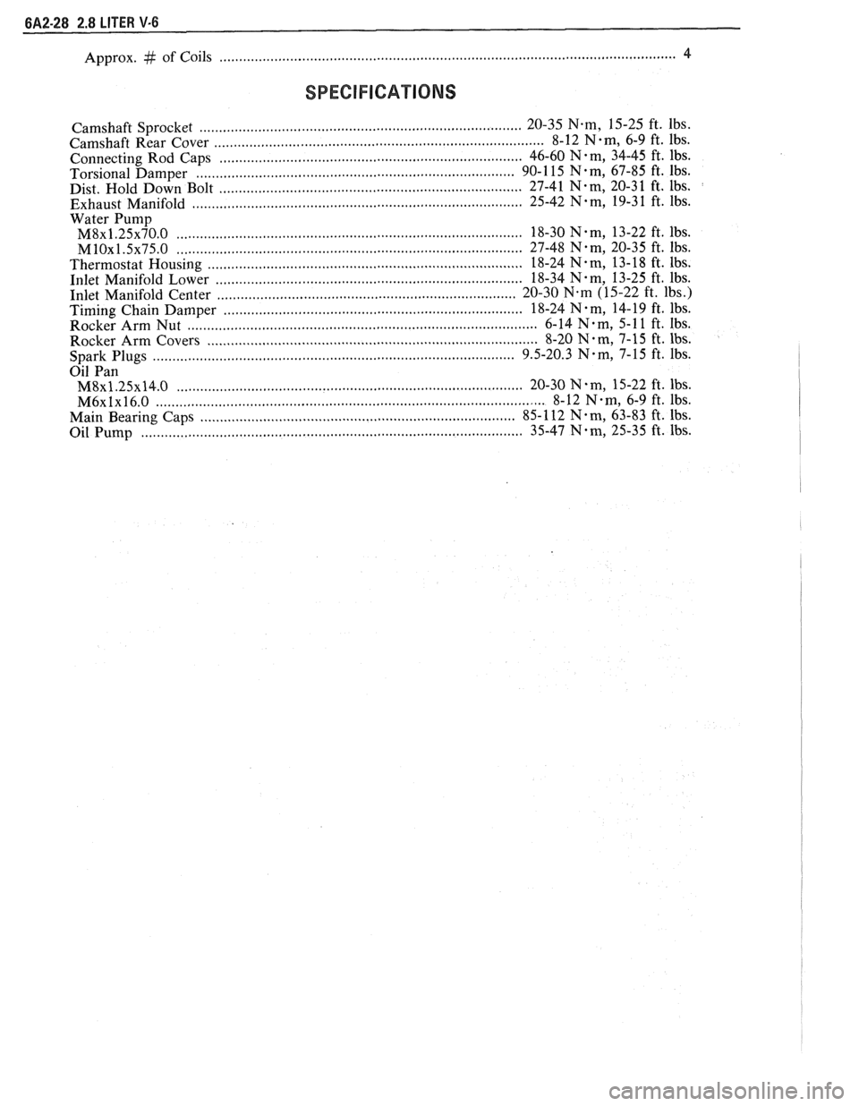
Approx. # of Coils ................................... .... ............................................................................. 4
SPECIFICATIONS
................................................................................ Camshaft Sprocket 20-35 N-m, 15-25
ft. lbs.
................................................................................... Camshaft Rear Cover 8-12 N-m, 6-9 ft. 1bs.
......................................................................... . Connecting Rod Caps 46-60 N m, 34-45
ft. lbs.
............................................................................ Torsional Damper 90-1
15 N-m, 67-85 ft. lbs.
Dist. Hold Down Bolt ..................... ..... ............................................... 27-41 N.m, 20-3 1 ft. lbs.
................................................................................. Exhaust Manifold 25-42 N.m, 19-3 1 ft. lbs.
Water
Pump
M8~1.25~70.0 ........................................................................................ 18-30 N.m, 13-22 ft. lbs.
MlOx1.5x75.0 .......................... .. ........................................................ 27-48 Nem, 20-35 ft. lbs.
Thermostat Housing ........................................................................... 18-24 N-m, 13-18 ft. lbs.
Inlet Manifold Lower
........................................................................... 18-34 N-m, 13-25 ft. lbs.
............................................ ........................ Inlet Manifold Center .. 20-30 N.m (15-22 ft. lbs.) ............................................................................ Timing Chain Damper 18-24
N . m, 14- 19 ft. lbs.
Rocker Arm Nut
........................................................................................ 6-14 N-m, 5-1 1 ft. Ibs.
Rocker Arm Covers
.................................................................................... 8-20 N-m, 7-15 ft. lbs. ........................................................................................ Spark Plugs 9.5-20.3 N-m, 7-15
ft. lbs.
Oil Pan
M8~1.25x14.0 .................................................................................... 20-30 N.m, 15-22 ft. lbs.
M6xlx16.0 ............................................................................................... 8-12 Nem, 6-9 ft. lbs.
................................................................................ Main Bearing Caps 85-
112 N. m, 63-83 ft. lbs.
Oil Pump
............................................................................................. 35-47 Nem, 25-35 ft. lbs.
Page 394 of 1825
V-8 ENGINE 6A3-15
engine to deliver the power and performance built into
it.
Another important factor is the cooling of the
valve heads. Good contact between each valve and its
seat in the head is imperative to insure that the heat in
the valve head will be properly carried away.
Several different types of equipment are available
for reseating valves seats. The recommendations of the
manufacturer of the equipment being used should be
carefully followed to attain proper results.
Regardless of what type of equipment is used,
however, it is essential that valve guide bores be free
from carbon or dirt to ensure proper centering of pilot
in the guide. Valve seats should be concentric to within
,002" total indicator reading.
VALVES
Valves that are pitted can be refaced to the proper
angle, insuring correct relation between the head and
stem on a valve
refacing mechanism. Valve stems
which show excessive wear, or valves that are warped
excessively should be replaced. When a valve head
which is warped excessively is
refaced, a knife edge will
be ground on part or all of the valve head due to the
amount of metal that must be removed to completely
reface. Knife edges lead to breakage, burning or
pre-ignition due to heat localizing on this knife edge.
If the edge of the valve head is less than 1/32"
(.08mm)
thick after grinding, replace the valve. Several different
types of equipment are available for
refacing valves.
The recommendation of the manufacturer of the
equipment being used should be carefully followed to
attain proper results.
TORSIONAL DAMPER
Removal
1.
Remove drive belts and pulley.
2. Raise vehicle.
3. Remove crankshaft pulley, then remove damper
retaining bolt.
4. Install Tool J-23523 on damper then, turning
puller screw, remove damper.
Installation
NOTICE: The inertial weight section of the
torsional damper is assembled to the hub with a
rubber type material. The installation procedures
(with proper tool) must be followed or movement
of the inertia weight section on the hub will
destroy the tuning of the torsional damper.
1. Inspect the cover seal contact area surface (on
damper) for damage or grooving and coat front
cover seal with engine oil.
2. Place damper in position over key on crankshaft.
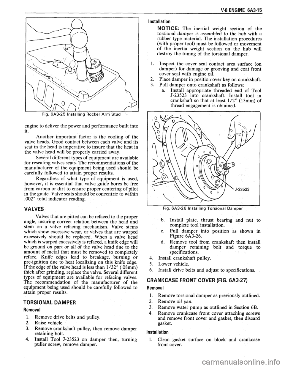
3. Pull damper onto crankshaft as follows:
a. Install appropriate threaded end of Tool
J-23523 into crankshaft. Install tool in
crankshaft so that at least
1/2" (13mm) of
thread engagement is obtained.
Fig. 6A3-26 Installing Torsional Damper
b.
Install plate, thrust bearing and nut to
complete tool installation.
c. Pull damper into position as shown in
Figure 6A3-26.
d. Remove tool from crankshaft then install
damper retaining bolt and torque to
specifications.
4. Install crankshaft pulley.
5. Lower vehicle.
6. Install drive belts and adjust to specifications.
CRANKCASE FRONT COVER (FIG. 6A3-27)
Removal
1.
Remove torsional damper as previously outlined.
2. Remove oil pan.
3. Remove water pump as outlined in Section
6B.
4. Remove crankcase front cover attaching screws
and remove front cover and gasket, then discard
gasket.
lnstallation
1. Clean gasket surface on block and crankcase
front cover.
Page 395 of 1825
6A3-16 V-8 ENGINE
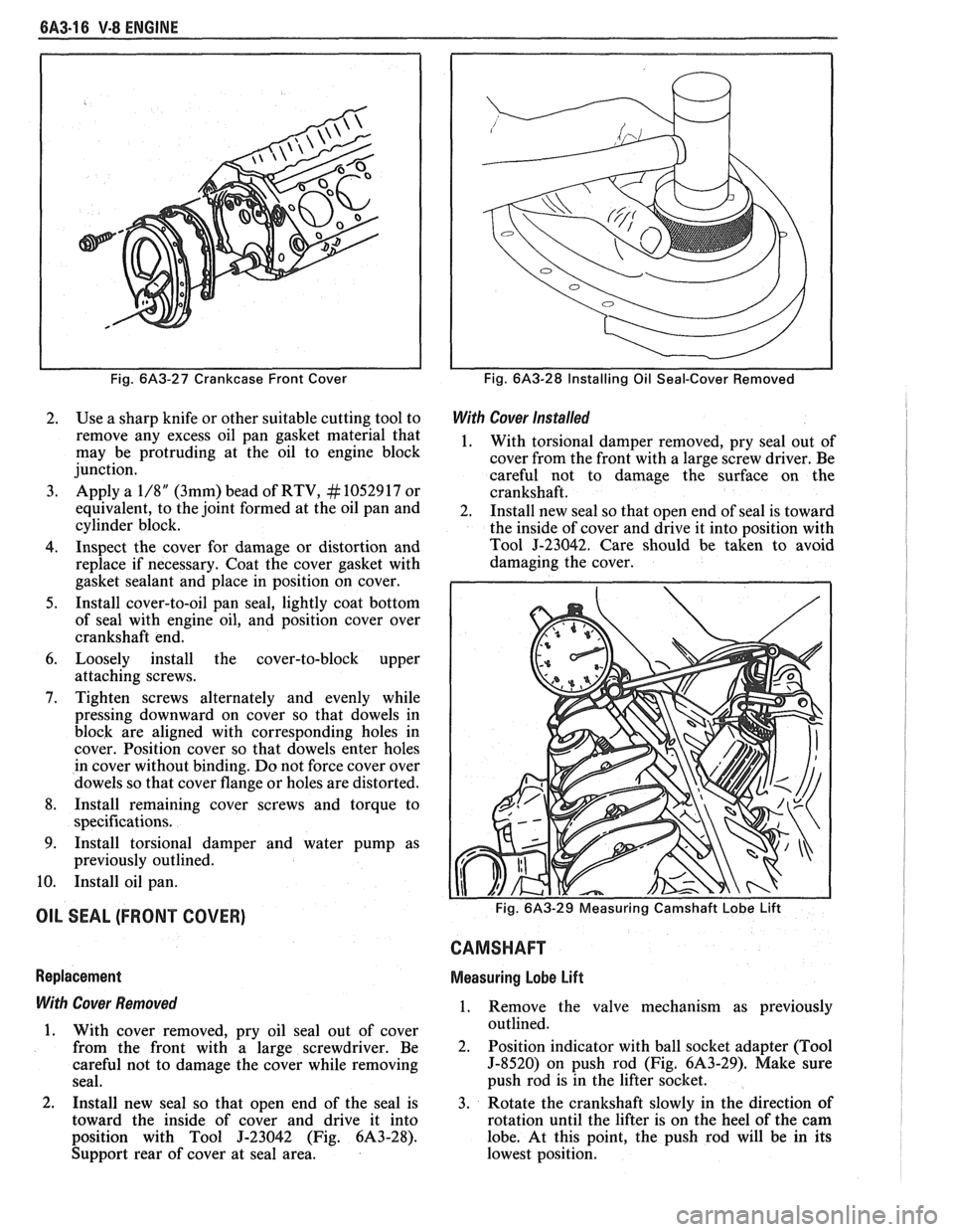
Fig. 6A3-27 Crankcase Front Cover
2. Use a sharp knife or other suitable cutting tool to
remove any excess oil pan gasket material that
may be protruding at the oil to engine block
junction.
3. Apply a 1/8" (3mm) bead of RTV, # 10529 17 or
equivalent, to the joint formed at the oil pan and
cylinder block.
4. Inspect the cover for damage or distortion and
replace if necessary. Coat the cover gasket with
gasket sealant and place in position on cover.
5. Install cover-to-oil pan seal, lightly coat bottom
of seal with engine oil, and position cover over
crankshaft end.
6. Loosely install the cover-to-block upper
attaching screws.
7. Tighten screws alternately and evenly while
pressing downward on cover so that dowels in
block are aligned with corresponding holes in
cover. Position cover so that dowels enter holes
in cover without binding.
Do not force cover over
dowels so that cover flange or holes are distorted.
8. Install remaining cover screws and torque to
specifications.
9. Install torsional damper and water pump as
previously outlined.
10. Install oil pan.
OIL SEAL (FRONT COVER)
Replacement
With Cover Removed
1. With cover removed, pry oil seal out of cover
from the front with a large screwdriver. Be
careful not to damage the cover while removing
seal.
2. Install new seal so that open end of the seal is
toward the inside of cover and drive it into
position with Tool
J-23042 (Fig. 6A3-28).
Support rear of cover at seal area.
Fig. 6A3-28 Installing Oil Seal-Cover Removed
With Cover Installed
1. With torsional damper removed, pry seal out of
cover from the front with a large screw driver. Be
careful not to damage the surface on the
crankshaft.
2. Install new seal so that open end of seal is toward
the inside of cover and drive it into position with
Tool
J-23042. Care should be taken to avoid
damaging the cover.
CAMSHAFT
Measuring Lobe Lift
1. Remove the valve mechanism as previously
outlined.
2. Position indicator with ball socket adapter (Tool
5-8520) on push rod (Fig. 6A3-29). Make sure
push rod is in the lifter socket.
3. Rotate the crankshaft slowly in the direction of
rotation until the lifter is on the heel of the cam
lobe. At this point, the push rod will be in its
lowest position.