1988 PONTIAC FIERO water pump
[x] Cancel search: water pumpPage 427 of 1825
6B-16 ENGINE COOLING
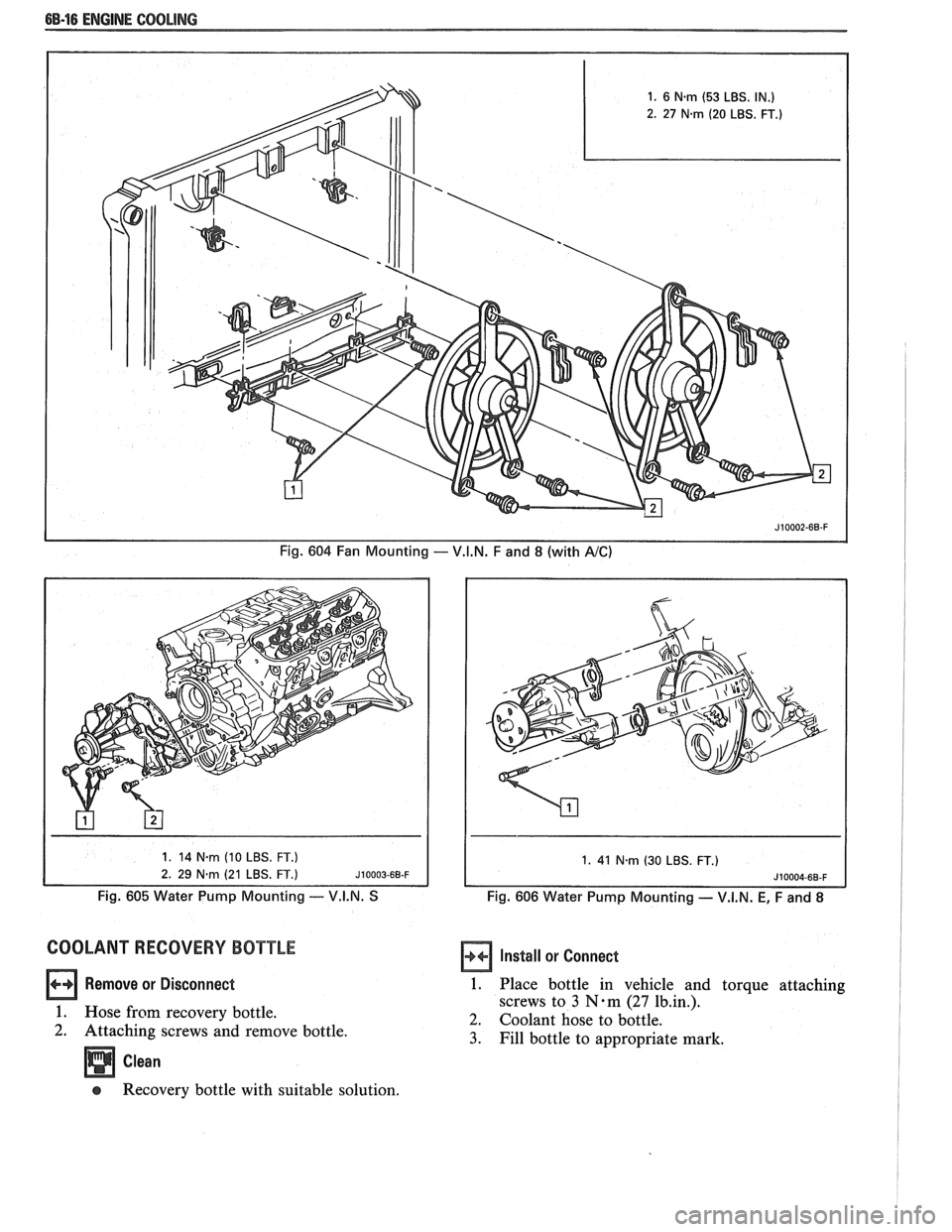
Fig. 604 Fan Mounting - V.I.N. F and 8 (with A/C)
1. 41 N-m (30 LBS. FT.)
Fig. 605 Water Pump Mounting -- V.I.N. S Fig. 606 Water Pump Mounting - V.I.N. E, F and 8
COOLANT RECOVERY EDOUTLE
Remove or Disconnect
1. Hose from recovery bottle.
2. Attaching screws and remove bottle.
Clean Install
or Connect
1. Place bottle in vehicle and torque attaching
screws to
3 N-m (27 1b.in.).
2. Coolant hose to bottle.
3. Fill bottle to appropriate mark.
@ Recovery bottle with suitable solution.
Page 430 of 1825
ENGINE COOLING 6B-19
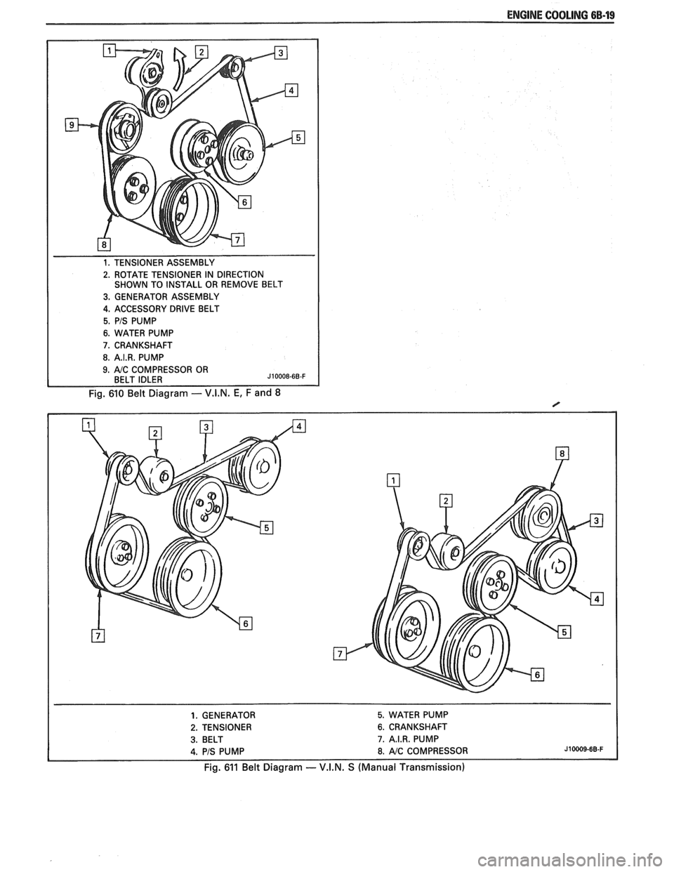
1. TENSIONER ASSEMBLY
2. ROTATE TENSIONER IN DIRECTION
SHOWN TO INSTALL OR REMOVE BELT
3. GENERATOR ASSEMBLY
4. ACCESSORY DRIVE BELT
5. PIS PUMP
6. WATER PUMP
7. CRANKSHAFT
8. A.I.R. PUMP
Fig. 610 Belt Diagram - V.I.N. E, F and 8
1. GENERATOR 5. WATER PUMP
2. TENSIONER 6. CRANKSHAFT
3. BELT 7. A.I.R. PUMP
4. PIS PUMP 8. AIC COMPRESSOR J10009-68-F
Fig. 611 Belt Diagram -- V.I.N. S (Manual Transmission)
Page 431 of 1825
6B-20 ENGINE COOLING
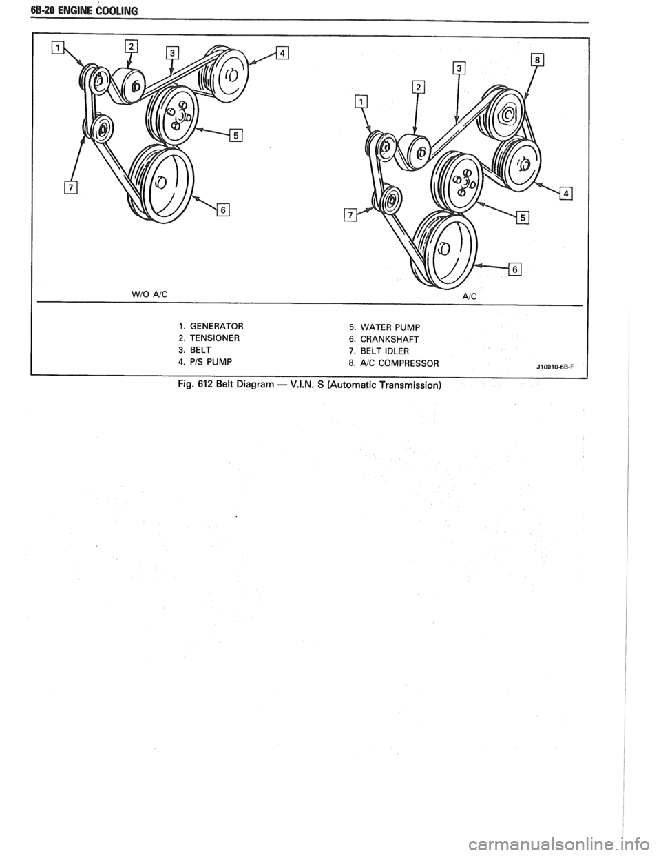
1. GENERATOR 5. WATER PUMP
2. TENSIONER 6. CRANKSHAFT
3. BELT 7. BELT IDLER
J10010-6B-F
Fig. 612 Belt Diagram - V.I.N. S (Automatic Transmission)
Page 433 of 1825

6C-2 ENGINE FUEL
components such as the accelerator pumps and/or
air-fuel mixture leaning effects.
Various types and concentrations of alcohols are
used in commercial gasoline. Some alcohols are more
detrimental to fuel system components than others. If
an excessive amount of alcohol in the fuel is suspected
as the cause of a driveability condition, the following
procedure may be used to detect the presence of
alcohol in the fuel.
In this procedure, water is used to
extract the alcohol from the fuel. However, the specific
type of alcohol is not determined.
The fuel sample should be drawn from the
bottom part of the tank so that any water, if already
present, can be detected. The sample should be bright
and clear. If the sample appears cloudy or
contaminated with water as indicated by a water layer
in the bottom part of the sample, this procedure should
not be used. The fuel system should then be cleaned
(See Fuel System Cleaning).
Testing Procedure
1. Using a 100 ml cylinder with 1 ml graduation
marks, fill with fuel to the 90 ml mark.
2. Add 10 ml of water to bring the total fluid volume
to 100 ml and install a stopper.
3. Shake vigorously for 10 to 15 seconds.
4. Carefully loosen stopper to release pressure.
5. Close the stopper and shake vigorously again for
10 to 15 seconds.
6. Carefully loosen
stopper to release pressure.
7. Put the graduated cylinder on a level surface for
approximately 5 minutes to allow adequate liquid
separation.
If alcohol is present in the fuel, the volume of the
lower layer, which would now contain alcohol and
water will be greater than 10 ml. For example, if the
volume of the lower layer is increased to 15 ml, it
would indicate at least 5 percent alcohol in fuel. The
actual amount of alcohol may be somewhat greater
because this procedure does not extract all of the
alcohol from the fuel.
FUEL METERING
Throttle Body lnjection
(TBI)
With Throttle Body Injection (TBI), an injection
unit is placed on the intake manifold where the
carburetor is normally mounted. The TBI unit is
computer controlled and supplies the correct amount
of fuel during all engine operating conditions. See
Section 6E2 for information relative to operation and
diagnosis of TBI units.
Port Fuel lnjection
The ECM is in complete control of this fuel
delivery system during all driving conditions.
The intake manifold is used only to let air into the
engine. Fuel is injected by separate injectors that are
mounted over the intake valve.
With the Port Injection System, there is no need
for a Thermac, EFE, Map Sensor, Baro Sensor, A.I.R.
System, or Dual Bed Converter. This
system provides better cold driveability,
lower exhaust emissions and better throttle response.
In Sequential Fuel Injection systems (SFI),
injectors turn on at every crankshaft revolution. The
ECM controls the injector "on" time so that the
correct amount of fuel is metered, depending on
driving conditions.
Two interchangeable
"0" rings are used on the
injector that must be inspected when the injectors are
removed. Check
"0" rings for cuts or other type of
damage and replace as necessary.
The air cleaner is remotely mounted near the
radiator. It is connected to the intake manifold by air
intake ducting.
Also, mounted between the air cleaner and
intake, are the mass air flow sensor and throttle body.
Cold driveability characteristics are greatly
improved with the aid of an engine coolant supply to
the throttle body for rapid warm up.
The throttle body design uses an integral Idle Air
Control to govern idle speed and a Throttle Position
Sensor (TPS). The IAC and TPS are both controlled
by the ECM.
A large diameter fuel rail is attached to the intake
manifold and supplies fuel to all the injectors.
A fuel pressure tap is located on the rail for quick
pressure checks.
Fuel is recirculated through the rail continually
while the engine is running. This removes air and
vapors from the fuel as well as keeping the fuel cool
during hot weather operation.
A fuel pressure regulator is mounted on the fuel
rail. It maintains a constant 36 psi pressure across the
injectors under all operating conditions. It is
accomplished by controlling the amount of fuel that is
recirculated back to the fuel tank, based on engine
demand.
The pressure regulator also uses an
"0" ring for
attachment. The
"0" ring used is the same one that is
used for the injectors.
Some engines also have an accumulator that is
located in the fuel feed line near the cowl area. It is used
to dampen the vibration that is caused by the
pressurized fuel and the pulsing of the injector.
See Section 6E3 for more information and
diagnosis.
Fuel Feed and Return Pipe
When replacing fuel feed and return pipes, always
replace them with welded steel tubing meeting GM
Specification
124M, or its equivalent. The replacement
pipe must use the same type of fittings as the original
pipes to ensure the integrity of the connection.
NOTICE: Do not replace fuel pipe with fuel hose
or any other type of tubing such as copper or
aluminum. Only tubing meeting the 124M
specification is capable of meeting all the pressure
and vibration characteristics necessary to ensure
the durability standard required.
Always check and replace any
"0" rings or
washers that appear damaged.
Page 436 of 1825
ENGINE FUEL CC-5
FUEL TANK
Draining Fuel Tank
1. Disconnect the negative battery cable. Also have
a dry chemical (Class B) fire extinguisher near the
work area.
2. Use a hand operated pump device when possible
to drain as much fuel through the filler tube as
possible.
3. If
a hand operated pump device cannot be used
to complete the draining process, use a siphon at
the main (not return) fuel pipe at the fuel pump
or the fuel tank gage unit.
CAUTION: Never drain or store
gasoline in an open container due to
the possibility of fire or explosion.
4. Reinstall any removed hoses, lines and cap.
Removing Fuel Tank
1. Remove all fuel, see "Draining Fuel Tank".
2. Support
fuel tank and disconnect the two fuel
tank retaining straps.
3. Lower tank enough to disconnect sending unit
wire, hoses, and ground strap, if so equipped.
4. Remove tank from vehicle.
5. Remove sending unit.
Installing Fuel Tank
1. Reverse removal procedure.
2. Always replace "0" ring when tank unit has been
removed.
3. When reinstalling fuel tank, be sure to reinstall
anti-squeak pieces on top of the tank to reduce
rattles and other annoying noises.
4. Tighten fuel tank retaining strap bolts or screws.
Fuel System Cleaning
CAUTION: This procedure will NOT
remove all fuel vapor. Do not attempt
any repair
on tank or filler neck where
heat or flame is required, as an
explosion resulting in personal injury
could occur.
If trouble is due to contaminated fuel or foreign
material that is in the tank, it can usually be cleaned.
If tank is rusted internally, it should be replaced.
1. Disconnect negative battery cable.
2. Disconnect ignition engine harness connector.
Have dry chemical (Class B) fire extinguisher
near the work area.
3. Relieve fuel system pressure.
4. Drain fuel tank (see "Draining Fuel Tank").
5. Remove fuel tank (see "Fuel Tank Removal").
6. Remove external fuel filter and inspect for
contamination. If filter is plugged, replace.
7. Locate tank away from heat, flame, or other
source of ignition. Remove fuel gage sending unit
and fuel pump assembly, if so equipped, and
inspect condition of strainer. If strainer is
contaminated, a new strainer should be installed.
8. Complete draining of tank by rocking it and
allowing fuel to run out of fuel sending unit
opening.
9. Flush fuel tank with running hot water for at least
five minutes. Pour water out of fuel sending unit
opening. (Rock tank to be sure that removal of
water is complete.)
10. Disconnect fuel feed pipe and use air pressure to
clean fuel line. Apply air pressure in the opposite
direction fuel normally flows through the line. On
vehicles equipped with a fuel return line, clean
line in similar manner. Disconnect pipe at
throttle body unit and apply air pressure to clean
return line. Reconnect and torque all pipes to 30
N-m (22 1b. ft.).
11. Use low air pressure to clean pipes on fuel gage
sending unit.
112. Install new strainer on fuel gage sending unit, if
required. Install fuel gage sending unit and fuel
pump, with new gasket, into tank and install fuel
tank. Connect fuel gage wire harness to body
harness. Connect all fuel lines except feed line to
external fuel filter.
13. Disconnect fuel feed hose to chassis pipe at front.
Connect a hose to front end of chassis fuel feed
pipe and insert other end of hose into a one gallon
fuel can.
14. Connect battery cable.
15. Put six gallons of clean fuel into fuel tank and
apply 12 volts to Terminal
"G" of ALCL to
operate fuel pump. Pump two quarts of fuel into
fuel can. This will purge fuel pump.
16. Remove hose and connect fuel hose to chassis
pipe.
17. Check all connections
for leaks; tighten all hose
clamps.
Fuel Tank Purging Procedure
The following procedure is used prior to repairing
of fuel tank.
1. Remove fuel sending unit and fuel pump and
drain all remaining fuel from tank.
2. Visually inspect interior cavity of tank. If any fuel
is evident, drain again.
3. Move tank to flushing area (wash rack).
4. Fill tank completely with tap water, agitate
vigorously and drain.
5. Add gasoline emulsifying agent to the tank, refill
with water, agitate mixture for 10 minutes, and
drain tank completely.
For correct gasoline emulsifying agent-to-water
mixture, refer to the
manufacturer's
specifications. Use an available emulsifying
agent, such as "Product-Sol No.
913", or
equivalent.
6. When empty, refill the tank to overflowing with
water. Completely flush out remaining mixture
and empty tank.
7. If available, an explosion meter should be used Lo
check for negative reading.
8. Perform required service work.
Page 505 of 1825
6E2-A-114 5.OL (VIN E) DRIVEABILITY AND EMISSIONS
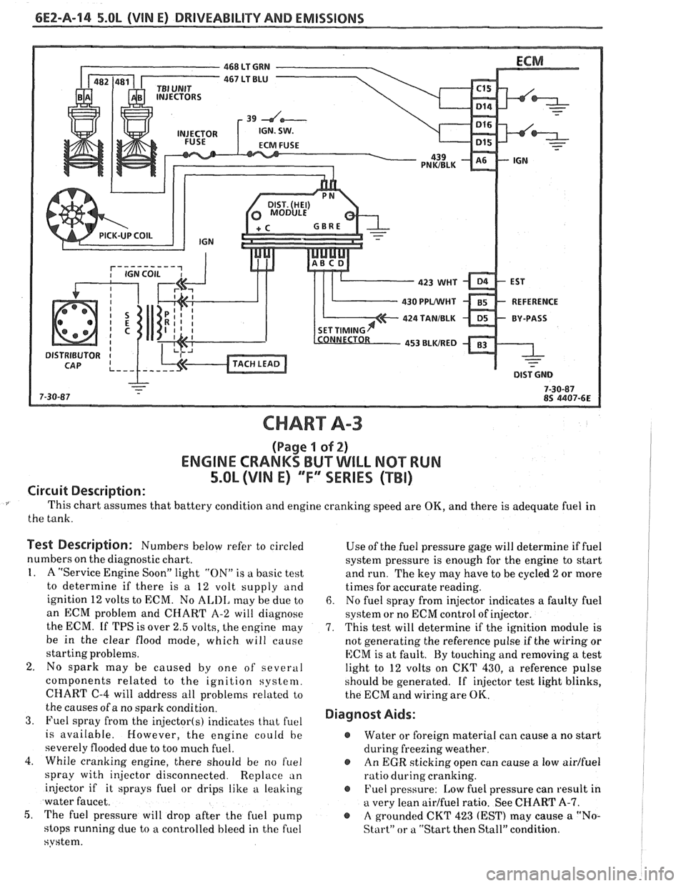
CHART A-3
(Page I of 2)
ENGINE CRANKS BUT WILL NQ"TRUN
5.OL (VIM E) "F"" SERlES (TBI)
Circuit Description:
This chart assumes that battery condition and engine cranking speed are OK, and there is adequate fuel in
the tank.
Test Description: Numbers below refer to circled
numbers on the diagnostic chart.
1. A "Service Engine Soon" light "ON" is a basic test
to determine if there is a 12 volt supply and
ignition 12 volts to ECM. No
ALIII, may be due to
an ECM problem and CHART A-2 will diagnose
the ECM. If TPS is over 2.5 volts, the engine may
be in the clear flood mode, which will cause
starting problems.
2. No spark may be caused by one of several
components related to the ignition system.
CHART
C-4 will address all problems related to
the causes of a no spark condition.
3. Fuel spray from the injector(s) indicates that fuel
is available. However, the engine could be
severely flooded due to too much fuel.
4. While cranking engine, there should be no
f~lel
spray with injector disconnected. Replace an
injector if it sprays fuel or drips like a leaking
water faucet.
5, The fuel pressure will drop after the fuel pump
stops running due to
a controlled bleed in the fuel
system. Use
of the fuel pressure gage will determine
if fuel
system pressure is enough for the engine to start
and run. The key may have to be cycled
2 or more
times for accurate reading.
6. No fuel spray from injector indicates a faulty fuel
system or no ECM control of injector.
7. This test will determine if the ignition module is
not generating the reference pulse if the wiring or
ECM is at fault. By touching and removing
a test
light to 12 volts on CKT 430,
a reference pulse
should be generated. If
injector test light blinks,
the ECM and wiring are
OK.
Diagnost Aids:
@ Water or foreign material can cause a no start
during freezing weather.
@ An EGR sticking open can cause a low airlfuel
ratio during cranking.
@ Fuel pressure: Low fuel pressure can result in
a very lean airlfuel ratio. See CHART A-7.
@ A grounded CKT 423 (EST) may cause a "No-
Start" or a "Start then Stall" condition.
Page 539 of 1825
6E2-A-48 5.OL, (VIN E) DRIVEABILITY AND f MISSIONS
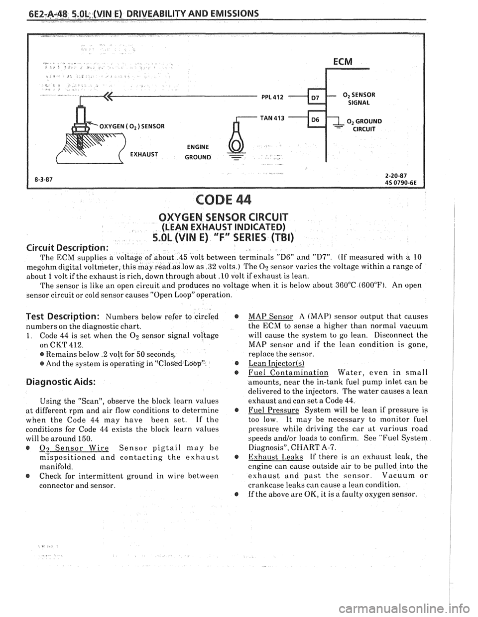
CODE 44
OXYGEN SENSOR CIRCUIT
(LEAN EXHAUST INDICATED)
5.OL (VIN E) "F" SERIES (TBI)
Circuit Description:
The ECM supplies a voltage of about .45 'volt between terminals "D6" and "117". (If measured with a 10
megohmdigital voltmeter, this may readas low as .32 volts.) The 02 sensor varies the voltage within a range of
about
1 volt if the exhaust is rich, down through about .I0 volt if exhaust is lean.
The sensor is like an open circuit and produces no voltage when it is below about
360°C (600°F). An open
sensor circuit or cold sensor causes "Open Loop" operation.
Test Description: Numbers below refer to circled @
numbers on the diagnostic chart.
1. Code 44 is set when the 02 sensor signal voltage
on
CK'l' 412.
@ Remains below .2 volt for 50 seconds,
@ And the system is operating in 'qClosk?d Loop". @
@
Diagnostic Aids:
Using the "Scan", observe the block learn values
at different rpm and air flow conditions to determine
@
when the Code 44 may have been set. If the
conditions for Code
44 exists the block learn values
will be around 150.
@ Q2 Sensor Wire Sensor pigtail may be
m?spositioned and contacting the exhaust @
manifold.
@ Check for intermittent ground in wire between
connector and sensor.
@
MAP Sensor A (MAP) sensor output that causes
the ECM to sense a higher than normal vacuum
will cause the
system to go lean. Disconnect the
MAP sensor and
if the lean condition is gone,
replace the sensor.
Lean
Iniectorts)
Fuel Contamination Water, even in small
amounts, near the in-tank fuel pump inlet can be
delivered to the injectors. The water causes
n lean
exhaust and can set a Code
44.
Fuel Pressure System will be lean if pressure is
too low.
It
may be necessary to monitor fuel
pressure while driving the car at various road
speeds
ancUor loads to confirm. See "Fuel System
Diagnosis",
CHART A-7.
Exhaust
Leaks If there is an exhaust leak, the
cngine can cause outside air to be pulled into the
eshaust
and past the sensor. Vacuum or
crankcase leaks can cause a lean condition.
If the above are OK, it is a faulty oxygen sensor.
Page 549 of 1825
6EZ-B-2 5.OL (VIN E) DRIVEABILITY AND EMISSIONS
Problem may or may not turn "ON" the "Service Engine Soon" light, or store a code.
DO NOT use the trouble code charts in Section
"A" for intermittent problems. The fault must be
present to locate the problem. If a fault is
intermittent, use of trouble code charts may result
in replacement of good parts.
@ Most intermittent problems are caused by faulty
electrical connections or wiring. Perform
careful check of suspect circuits for:
- Poor mating of the connector halves, or
terminals, not fully seated in the connector
body (backed out).
I - Improperly formed or damaged terminals.
All connector terminals in problem circuit
should be carefully reformed to increase
contact tension.
- Poor terminal to wire connection. This
requires removing the terminal from the
connector body to check as outlined in the
Introduction to Section
"6E".
@ If a visual (physical) check does not find the
cause of the problem, the car can be driven with
a voltmeter connected to a suspected circuit or a
"Scan" tool may be used. An abnormal voltage
reading, when the problem occurs, indicates the
problem may be in that circuit. If the wiring
and connectors check OK, and a trouble code was
stored for a circuit having a sensor, except
for Codes 44 and 45, substitute a known good
sensor and recheck.
@ Loss of trouble code memory. To check,
disconnect TPS and idle engine until "Service
Engine Soon" light comes
"ON". Code 22 should
be stored, and kept in memory, when ignition is
turned "OFF" for at least 10 seconds. If not, the
ECM
is faulty.
@ An intermittent "SES" light, and no trouble
codes, may be caused by:
- Electrical system interference caused by a
defective relay, ECM driven solenoid, or switch.
They can cause a sharp electrical surge.
Normally, the problem will occur when the
faulty component is operated.
- Improper installation of electrical options, such
as lights, 2-way radios, etc.
- EST wires should be routed away from spark
plug wires, ignition system components, and
generator. Wire for CKT 453 from ECM to
ignition system should be a good ground.
- Ignition secondary shorted to ground.
- CKTs 419 ("SES" light) or 451 (Diagnostic Test)
intermittently shorted to ground.
- ECM power grounds.
HARD START
Definition: Engine cranks OK, but does not start for a long
time. Does eventually run, or may start but immediately dies.
, <
@ CHECK: 4. Connect a radiator test pump to the line and
- For water contaminated fuel. apply 103 kPa (15 psi) pressure. If the
- Fuel system pressure CHART A-7. pressure will hold for 60 seconds, the check
- TPS for sticking or binding should read less than
valve is OK.
1.25 volts on a "Scan" tool. @ Check ignition system for:
- No crank signal; see CHART C-1B. - Proper output with ST-125.
- EGR operation; CHART C-7. - Worn shaft.
- Fuel System - CHART A-7. - Rare and shorted wires.
- For a faulty in-tank fuel pump check valve, - Pickup coil resistance and connections.
which would allow the fuel in the lines to drain
- Loose ignition coil connections.
back to the tank after the engine is stopped. To
- Moisture in distributor cap.
check for this condition:
- Spark plugs, wet plugs, cracks, wear,
1. Ignition "OFF".
improper gap, burned electrodes, or heavy
2. Disconnect fuel line at the filter
deposits.
3. Remove the tank filler cap. @ If engine starts but then, immediately stalls,
open distributor bypass line. If engine then
starts, and runs OK, replace distributor pickup
coil.
@ Check CKT 423 (EST) for short to ground.