1988 PONTIAC FIERO water pump
[x] Cancel search: water pumpPage 868 of 1825
DRIVEABILITY AND EMISSIONS 5.OL (VIN F) & 5.7L (VIN 8) 6E3-8-3
@ A faulty in-tank fuel pump check valve will @
allow the fuel in the lines to drain back to the
tank after the engine is stopped. To check for
this condition:
e
Perform Fuel System Diagnosis, CHART A-7.
@ Remove spark plugs. Check for wet plugs,
cracks, wear, improper gap, burned electrodes,
@
or heavy deposits. Repair or replace as
necessary. If
engine starts but then immediately stalls
open distributor by-pass line. If engine then
starts and runs OK, replace pickup coil.
If engine starts and stalls disconnect MAF
sensor. If engine then
r~lns and sensor
connections are OK, replace
thr. )t.ft+rl'.
Basic engine problem.
HESITATION, SAG, STUMBLE
Definition: Momentary lack of response as the accelerator i., pl,ihcc! dowt-
Can occur at all car speeds. Usually most severe when first tryine, lo m,tlir. LII~.
car move, as from a stop sign. May cause the engine to sta!! 1, e er., riu~~~!~
s Perform careful visual check as described at
start of Section
"B".
@ CHECK:
- Fuel pressure. See CHART A-7. Also, check
for water contaminated fuel.
- Air leaks at air duct between MAF sensor and
throttle body.
- Spark plugs for being fouled or faulty wiring.
- Mem-Cal number. Also check service bulletins
for latest Mem-Cal.
- TPS for binding or sticking. Voltage should
increase at
a steady rate as throttle is moved
toward WOT.
- Ignition timing. See emission control
information label.
- Generator output voltage. Repair if less than 9
or more than 16 volts.
- HE1 ground, CKT 453.
- Canister purge system for proper operation.
See CHART C-3.
- EGR - See CHART C-7.
e Perform injector balance test CHART C-2A.
SURGES AND/OR CHUGGLE
Definition: Engine power variation under steady
throttle or cruise. Feels like the car speeds up and
slows down with no change in the accelerator pedal.
@ Be sure driver understands transmission
converter clutch and
AJC compressor operation
in owner's manual.
Perform careful visual inspection as described
at start of Section
"B".
e CHECK:
- Loose or leaking air duct between MAF sensor
and throttle body.
- Generator output voltage. Repair if less than 9
or more than 16 volts.
- EGR - There should be no EGR at idle. See
CHART C-7.
- Vacuum lines for kinks or leaks.
- Ignition timing. See emission control
information label.
- In-line fuel filter. Replace if dirty or plugged.
- Fuel pressure while condition exists. See
CHART A-7.
@ Inspect oxygen sensor for silicon contamination
from fuel, or use of improper RTV sealant. The
sensor may have a white, powdery coating and
result in a high but false signal voltage (rich
exhaust indication). The ECM will then reduce
the amount of fuel delivered to the engine,
causing a severe driveability problem.
@ Remove spark plugs. Check for cracks, wear,
improper gap, burned electrodes, or heavy
deposits. Also check condition of distributor
cap, rotor, and spark plug wires.
@ To help determine if the condition is caused by a
rich or lean system, the car should be driven at
the speed of the complaint. Monitoring block
learn at the complaint speed will help identify
the cause of the problem.
If the system is lean
(block learn greater than
1381, refer to
"Diagnostic Aids"
on facing page of Code 44. If
the system is running rich (block learn less than
1181, refer to "Diagnostic Aids" on facing page
of Code
45.
Page 869 of 1825
6E3-B-4 5.OL (VIN F) & 5.7L (VIN 8) DRIVEABILITY AND EMISSIONS
LACK OF POWER, SLUGGISH, OR SPONGY
Definition: Engine delivers less than expected power. Little or
no increase in speed when accelerator pedal is pushed down part way.
@ Perform careful visual check as described at
start of Section "B".
@ Compare customer's car to similar unit.
Make sure the customer's car has an actual
problem.
@ Remove air cleaner and check air filter for
dirt, or for being plugged. Replace as
necessary.
@ CHECK:
- For loose or leaking air duct between MAF
sensor and throttle body.
- Ignition timing. See emission control
information label.
- Restricted fuel filter, contaminated fuel or
improper fuel pressure. See CHART A-7.
- ECM Ground circuits - See ECM wiring
diagrams.
- EGR operation for being open, or partly open
all the time
- CHART C-7.
- Exhaust system for possible restriction: See
CHART
B-1.
- Inspect exhaust system for damaged or
collapsed pipes.
- Inspect muffler for heat distress or possible
internal failure.
- For possible plugged catalytic convertor by
comparing exhaust system backpressure on
each side at engine. Check backpressure by
removing
A.1.R check valves near exhaust
manifolds. See CHART
B-1 for procedure.
- Generator output voltage. Repair if less than 9
or more than 16 volts.
- Engine valve timing and compression.
- Engine for proper or worn camshaft. See Section
"6A".
- Secondary voltage using a shop ocilliscope or a
spark tester
5-26792 (ST-125) or equivalent.
- Check for excessive knock retard. See CHART
C-5.
DETONATION ISPARK KNOCK
Definition: A mild to severe ping, usually worse under
acceleration. The engine makes sharp metallic knocks that
change with throttle opening. Sounds like popcorn popping.
@ Check for obvious overheating problems:
- Low coolant.
- Loose water pump belt.
- Restricted air flow to radiator, or restricted
water flow thru radiator.
- Inoperative electric cooling fan circuit. See
CHART C-12.
@ CHECK:
- Ignition timing. See vehicle emission control
information label.
- EGR system for not opening - CHART C-7.
- TCC operation - CHART C-8.
- Fuel system pressure. See CHART A-7.
- Mem-Cal - Be sure it's the correct one. (See
"Service Bulletins").
- Valve oil seals for leaking.
@ Check for incorrect basic engine parts such as
cam, heads, pistons, etc.
@ Checkforpoorfuelquality.
@ Remove carbon with top engine cleaner. Follow
instructions on can.
@ Check ESC system
See CHART C-5
@ To help determine if the condition is caused by a
rich or lean system, the car should be driven at
the speed of the complaint. Monitoring block
learn at the complaint speed will help identify the
cause of the
problem. If the system is runnig lean
(block learn greater than
1381, refer to
"Diagnostic Aids" on facing page of Code
44. If
the system is running rich (block learn less than
1181, refer to "Diagnostic Aids" on facing page of
Code 45.
Page 930 of 1825
DRlVEABlLlfVAND EMISSIONS 5.OL (VIN F) & 5.7L (VIN 8) 6E3-C6-3
Hoses and Pipes
1. Hose or pipe for deterioration or holes.
2. All hoses or pipe connections, and clamp tightness.
3. Hose or pipe routing. Interference may cause
wear.
4. If
a leak is suspected on the pressure side of the
system or if a hose or pipe has been disconnected
on the pressure side, the connections should be
checked for leaks with a soapy water solution.
With the pump running, bubbles will form if a
leak exists.
Check Valve
Inspect
1. A check valve should be inspected whenever the
hose is disconnected from a check valve or
whenever check valve failure is suspected.
(A
pump that had become inoperative and had shown
indications of having exhaust gases in the pump
would indicate check valve failure).
2. Blow through the check valve (toward the cylinder
head) then attempt to suck back through the check
valve. Flow should only be in one
direction(toward the exhaust manifold). Replace
valve which does not operate properly.
ON-CAR SERVICE
DRIVE BELT
Remove or Disconnect
1. Inspect drive belt for wear, cracks or deterioration
and replace if required. When installing a new
belt, it must be seated and fully secured in grooves
of all belt driven components.
AIR INJECTION PUMP
Remove or Disconnect
1. Hold pump pulley from turning by cotnpressing
drive belt, then loosen pump pulley bolts.
2. Drive belt and pulley.
3. Hoses, vacuum, and electrical connections from
air injection control valve.
4. Air pump mounting bolts, and pump assembly
(See Figure
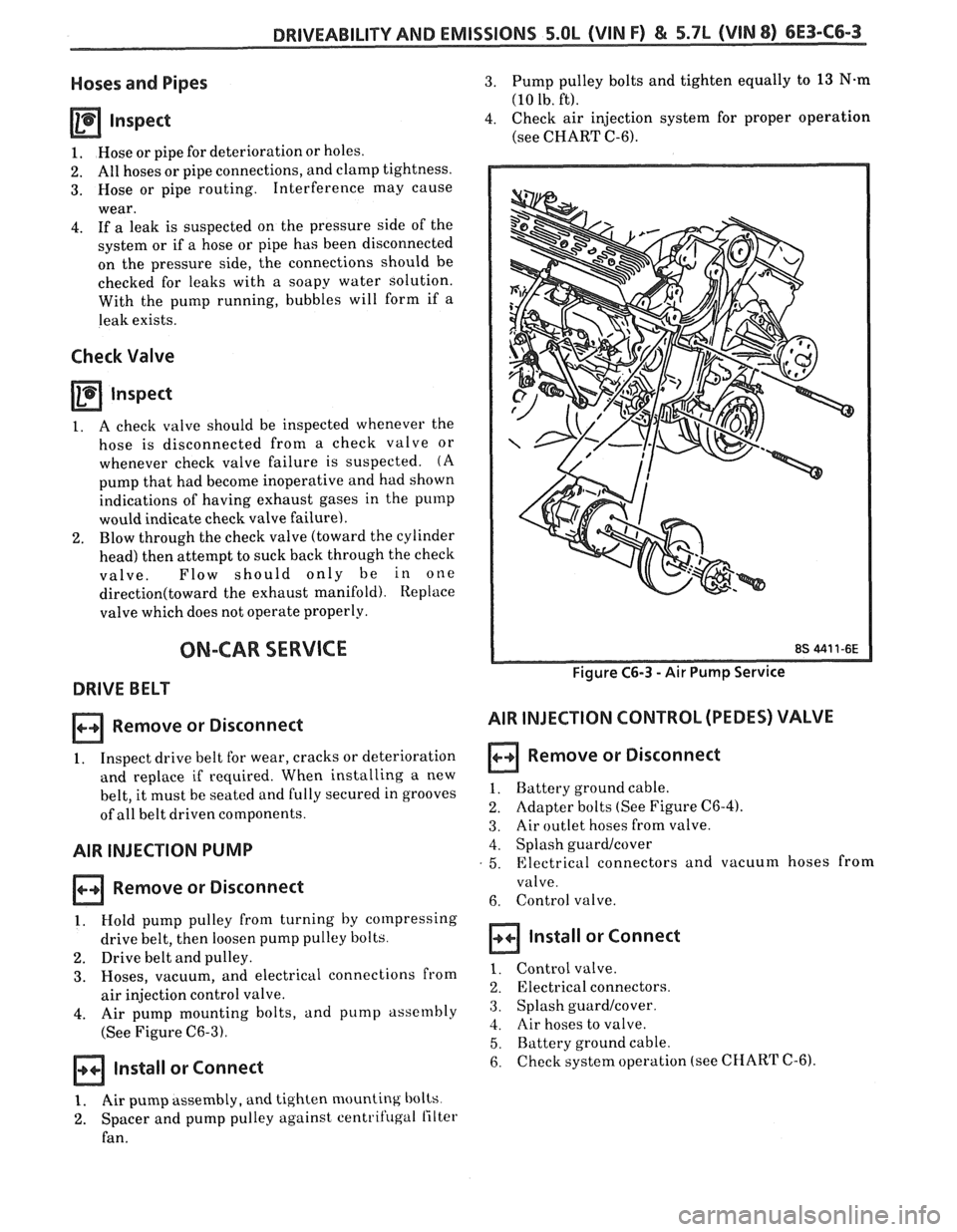
C6-3).
Install or Connect
3. Pump pulley bolts and tighten equally to 13 N.m
(10 lb. ft).
4. Check air injection system for proper operation
(see CHART C-6).
Figure C6-3 - Air Pump Service
AIR INJECTION CONTROL (PEDES) VALVE
Remove or Disconnect
1. Battery ground cable.
2. Adapter bolts (See Figure C6-4).
3. Air outlet hoses from valve.
4. Splash guardlcover
5. Electrical connectors and vacuum hoses from
valve.
6. Control valve.
Install or Connect
1. Control valve.
2. Electrical connectors.
3. Splash guard/cover.
4. Air hoses to valve.
5. Battery ground cable.
6. checksystem operation (see CHART C-6).
1. Air pump assembly, and tighten mounting bolts
2. Spacer and pump pulley against centrifugal lilter
fan.
Page 1122 of 1825
AUTOMATIC TMNSMISSION ON-VEHICLE SERVICE 7A1-3
e Propeller shaft oil seal worn or damaged
o Governor cover
e Line pressure pipe plug loose
@ Porous casting
3. Leak at converter end:
Converter seal damaged
- Seal lip cut. (Check converter hub for
damage.)
- Bushing moved forward and damaged
- Garter spring missing from seal
o Converter leak in weld area. (Refer to
Torque Converter.)
Porous casting (Case or pump)
4. Fluid comes out vent pipe or fill tube:
Over-filled
Water or coolant in fluid. Fluid will appear
milky.
e Case porous
e Incorrect fluid level indicator
e Plugged vent
e Drain back holes plugged
Mispositioned oil pump to case gasket (if
equipped)
Case Porosity Repair
1. Clean the leak area with solvent and air dry.
CAUTION: Epoxy adhesive may cause
skin irritations and eye damage. Read
and follow all information on the
container label as provided by the
manufacturer.
2. Mix a sufficient amount of epoxy adhesive,
# 1052533, or equivalent, following the
manufacturer's recommendations.
3. While the transmission case is hot, apply epoxy
adhesive with a clean, dry soldering acid brush.
4. Allow the epoxy adhesive to cure for three hours
before starting the engine.
5. Repeat fluid leak diagnosis procedures.
TORQUE CONVERTER CLUTCH ELECTRICAL
CONTROLS
The Torque Converter Clutch (TCC) system uses
controls that are internal as well as external to the
transmission. For internal control components of the
TCC system, refer to the I-Iydraulic Diagnosis Section
for for wiring diagrams and switch locations.
The external control components of the TCC
system include:
1. Brake Release Switch - To avoid stalling the
engine when braking, the converter clutch is
released any time the brakes are applied.
2. Electronic Control ModuOe - Receives input
signals and grounds TCC solenoid to apply clutch
when proper operating conditions are met.
3. Throttle Position Sensor - Sends throttle
position information to Electronic Control
Module.
4. Vacuum Sensor - Sends engine vacuum (load)
information to Electronic Control Module.
5. Vehicie Speed Sensor - Sends vehicle speed
information to Electronic Control Module.
6. Coolant Temperature Sensor - Sends engine
coolant temperature information to Electronic
Control Module.
TORQUE CONVERTER CLUTCH DIAGNOSIS
To properly diagnose the Torque Converter
Clutch (TCC) system perform all electrical testing first
and then the hydraulic testing. Refer to the appropriate
Driveability and Emissions Section (6E) for additional
Torque Converter Clutch Information
ON-VEHICLE SERVICE
SI-IIFT CONTROL CABLE
Remove or Disconnect (Fig. 1)
1. Negative battery cable.
2. Raise car, see Section OA.
3. Cable attachments at transmission.
4. Lower car.
5. Console, see Section
8C.
6. Cable at control lever and base.
7. Cable from floor.
install or Connect
1. Cable to floor.
2. Cable at base and control lever.
3. Console, see Section 8C.
4. Place control lever in "NEUTRAL"
5. Raise car.
6. Cable attachments at transmission.
7. Adjust cable.
8. Lower car.
9. Negative battery cable.
Adjust (Fig. 1)
1. Place control lever in "N" (Neutral).
2. Raise car, see Section 0.4.
3. Loosen cable
attachment at shift lever.
4. Rotate shift lever "clockwise" to park detent and
then back to neutral.
5. Tighten cable attachment.
15
N-m (11 lbs. ft.)
Important
Levg must be held out of "PARK" when
torquing nut.
6. Lower car.
7. Check cable adjustment by rotating control lever
thru the detents.
Remove or Disconnect (Fig. 2)
1. Negative battery cable.
2. Console, see Section 8C.
3. Cable at control lever and base.
Page 1622 of 1825
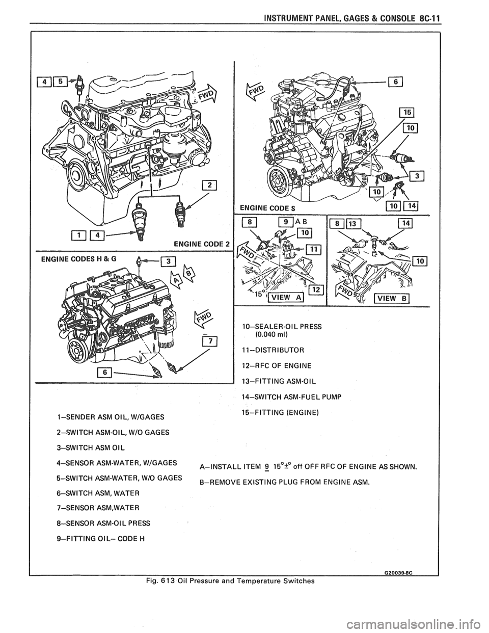
INSTRUMENT PANEL. GAGES & CONSOLE 8C-11
ENGINE CODE 2
ENGINE CODES H & G
10-SEALER-OI L PRESS
(0.040 ml)
12-RFC OF ENGINE
13-FITTING ASM-OIL
14-SWITCH ASM-FUEL PUMP
I
1-SENDER ASM OIL, WIGAGES 15-FITTING (ENGINE)
I
2-SWITCH ASM-OI L, WIO GAGES
3-SWITCH ASM OIL
4-SENS0R ASM-WATER' A-INSTALL ITEM g 15'9 off OFF RFC OF ENGINE AS SHOWN.
ASM-WATER' W1O GAGES B-REMOVE EXISTING PLUG FROM ENGINE ASM.
6-SWITCH ASM, WATER
8-SENSOR ASM-OI L
PR ESS
I 9-FITTING OIL- CODE H
Fig.
6 13 Oil Pressure and Temperature Switches
Page 1629 of 1825
8E -2 WINDSHIELD WIPER SYSTEMS F CARLINE
brush circuit (Fig. 12) is completed to the (+) 12 volts
DC source and the wiper motor runs at that particular
speed setting.
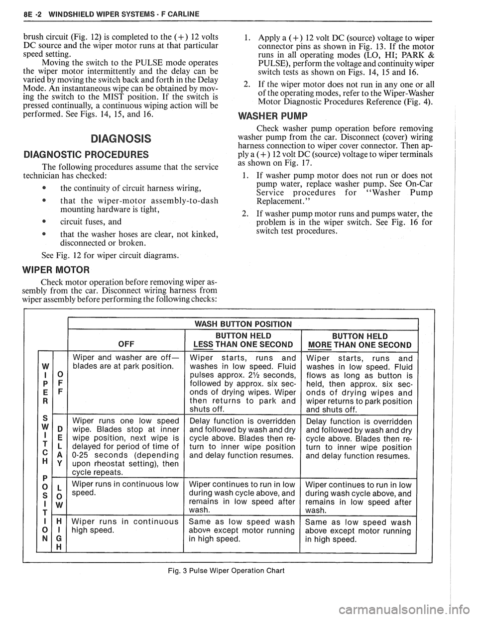
Moving the switch to the PULSE mode operates
the wiper motor intermittently and the delay can be
varied by moving the switch back and forth in the Delay
Mode. An instantaneous wipe can be obtained by mov-
ing the switch to the MIST position. If the switch is
pressed continually, a continuous wiping action will be
performed. See Figs. 14,
15, and 16.
DIAGNOSVC PROCEDURES
The following procedures assume that the service
technician has checked:
@ the continuity of circuit harness wiring,
@ that the wiper-motor assembly-to-dash
mounting hardware is tight,
circuit fuses, and
@ that the washer hoses are clear, not kinked,
disconnected or broken.
1. Apply a (+) 12 volt DC (source) voltage to wiper
connector pins as shown in Fig. 13. If the motor
runs in all operating modes
(LO, HI; PARK &
PULSE), perform the voltage and continuity wiper
switch tests as shown on Figs. 14, 15 and 16.
2. If the wiper motor does not run in any one or all
of the operating modes, refer to the Wiper-Washer
Motor Diagnostic Procedures Reference (Fig.
4).
WASHER PUMP
Check washer pump operation before removing
washer pump from the car. Disconnect (cover) wiring
harness connection to wiper cover connector. Then ap-
ply a
(+) 12 volt DC (source) voltage to wiper terminals
as shown on Fig. 17.
1. If washer pump motor does not run or does not
pump water, replace washer pump, See On-Car
Service procedures for "Washer Pump
Replacement.
' '
2. If washer pump motor runs and pumps water, the
problem is in the wiper switch. See Fig. 16 for
switch test procedures.
See Fig. 12 for wiper circuit diagrams.
WIPER MOTOR
Check motor operation before removing wiper as-
sembly from the car. Disconnect wiring harness from
wiper assembly before performing the following checks:
Fig. 3 Pulse Wiper Operation Chart
Page 1717 of 1825
5H.4 DOORS - F STYLE
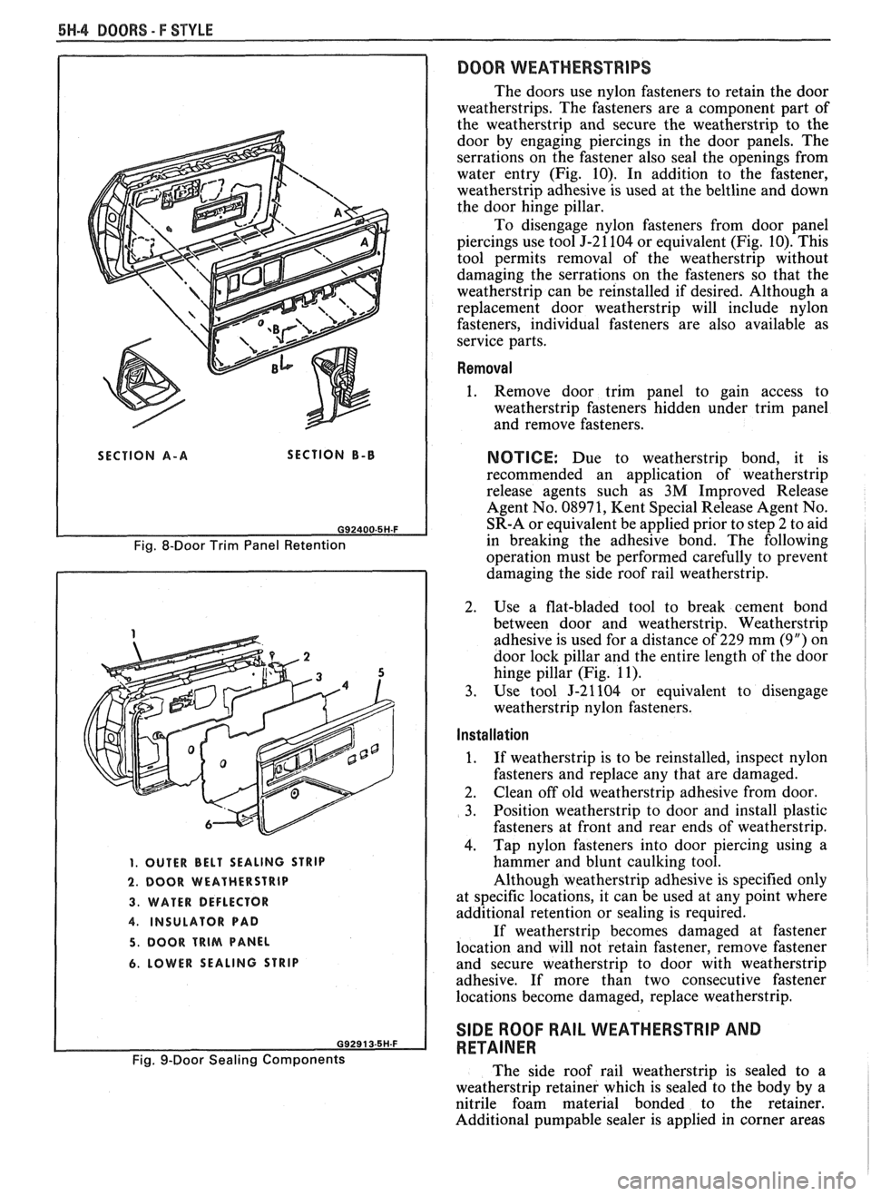
SECTION A-A SECTION B-B
Fig. 8-Door Trim Panel Retention
1. OUTER BELT SEALING STRIP
2. DOOR WEATHERSTRIP
3. WATER DEFLECTOR
4. INSULATOR PAD
5. DOOR TRIM PANEL
6. LOWER SEALING STRIP
Fig. 9-Door Sealing Components
DOOR WEATHERSTRIPS
The doors use nylon fasteners to retain the door
weatherstrips. The fasteners are a component part of
the weatherstrip and secure the weatherstrip to the
door by engaging piercings in the door panels. The
serrations on the fastener also seal the openings from
water entry (Fig. 10). In addition to the fastener,
weatherstrip adhesive is used at the
beltline and down
the door hinge pillar.
To disengage nylon fasteners from door panel
piercings use tool J-21104 or equivalent (Fig. 10). This
tool permits removal of the weatherstrip without
damaging the serrations on the fasteners so that the
weatherstrip can be reinstalled if desired. Although a
replacement door weatherstrip will include nylon
fasteners, individual fasteners are also available as
service parts.
Removal
1. Remove door trim panel to gain access to
weatherstrip fasteners hidden under trim panel
and remove fasteners.
NOTICE: Due to weatherstrip bond, it is
recommended an application of weatherstrip
release agents such as
3M Improved Release
Agent No. 08971, Kent Special Release Agent No.
SR-A or equivalent be applied prior to step 2 to aid
in breaking the adhesive bond. The following
operation must be performed carefully to prevent
damaging the side roof rail weatherstrip.
2. Use a flat-bladed tool to break cement bond
between door and weatherstrip. Weatherstrip
adhesive is used for a distance of 229 mm (9") on
door lock pillar and the entire length of the door
hinge pillar (Fig. 11).
3. Use tool J-21104 or equivalent to disengage
weatherstrip nylon fasteners.
Installation I 1
1. If weatherstrip is to be reinstalled, inspect nylon
fasteners and replace any that are damaged.
2. Clean
off old weatherstrip adhesive from door.
3. Position weatherstrip to door and install plastic
fasteners at front and rear ends of weatherstrip.
4. Tap
nylon fasteners into door piercing using a
hammer and blunt caulking tool.
Although weatherstrip adhesive is specified only
at specific locations, it can be used at any point where
additional retention or sealing is required.
If weatherstrip becomes damaged at fastener
location and will not retain fastener, remove fastener
and secure weatherstrip to door with weatherstrip
adhesive. If more than two consecutive fastener
locations become damaged, replace weatherstrip.
SIDE ROOF RAIL WEATHERSTRIP AND
RETAINER
The side roof rail weatherstrip is sealed to a
weatherstrip retainer which is sealed to the body by a
nitrile foam material bonded to the retainer.
Additional
pumpable sealer is applied in corner areas
Page 1719 of 1825
5W-8 BOORS - F STYLE
3. With weatherstrip removed, screws securing
weatherstrip retainer to side roof rail are exposed.
Mark position of retainer on rail or pillar and
remove screws from retainer.
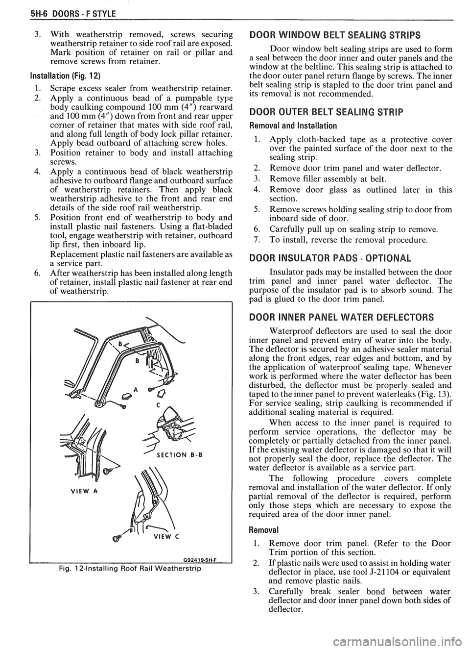
Installation (Fig. 1 2)
1.
Scrape excess sealer from weatherstrip retainer.
2. Apply a continuous bead of a
pumpable type
body caulking compound 100 mm (4") rearward
and 100 mm (4") down from front and rear upper
corner of retainer that mates with side roof rail,
and along full length of body lock pillar retainer.
Apply bead outboard of attaching screw holes.
3. Position retainer to body and install attaching
screws.
4. Apply a continuous bead of black weatherstrip
adhesive to outboard flange and outboard surface
of weatherstrip retainers. Then apply black
weatherstrip adhesive to the front and rear end
details of the side roof rail weatherstrip.
5. Position front end of weatherstrip to body and
install plastic nail fasteners. Using a flat-bladed
tool, engage weatherstrip with retainer, outboard
lip first, then inboard lip.
Replacement plastic nail fasteners are available as
a service part.
6. After weatherstrip has been installed along length
of retainer, install plastic nail fastener at rear end
of weatherstrip.
SECTION B-B
Fig. 12-Installing Roof Rail Weatherstrip
DOOR WINDOW BELT SEALING STRIPS
Door window belt sealing strips are used to form
a seal between the door inner and outer panels and the
window at the beltline. This sealing strip is attached to
the door outer panel return flange by screws. The inner
belt sealing strip is stapled to the door trim panel and
its removal is not recommended.
DOOR OUER BELT SEALING STRIP
Removal and Installation
1.
Apply cloth-backed tape as a protective cover
over the painted surface of the door next to the
sealing strip.
2. Remove door trim panel and water deflector.
3. Remove filler assembly at belt.
4. Remove door glass as outlined later in this
section.
5. Remove screws holding sealing strip to door from
inboard side of door.
6. Carefully pull up on sealing strip to remove.
7. To install, reverse the removal procedure.
DOOR INSULAWR PADS - OPTIONAL
Insulator pads may be installed between the door
trim panel and inner panel water deflector. The
purpose of the insulator pad is to absorb sound. The
pad is glued to the door trim panel.
DOOR INNER PANEL WATER DEFLECTORS
Waterproof deflectors are used to seal the door
inner panel and prevent entry of water into the body.
The deflector is secured by an adhesive sealer material
along the front edges, rear edges and bottom, and by
the application of waterproof sealing tape. Whenever
work is performed where the water deflector has been
disturbed, the deflector must be properly sealed and
taped to the inner panel to prevent waterleaks (Fig. 13).
For service sealing, strip caulking is recommended if
additional sealing material
is required.
When access to the inner panel is required to
perform service operations, the deflector may be
completely or partially detached from the inner panel.
If the existing water deflector is damaged so that it will
not properly seal the door, replace the deflector. The
water deflector is available as a service part.
The following procedure covers complete
removal and installation of the water deflector. If only
partial removal of the deflector is required, perform
only those steps which are necessary to expose the
required area of the door inner panel.
Removal
1. Remove door trim panel. (Refer to the Door
Trim portion of this section.
2. If plastic nails were used to assist in holding water
deflector in place, use tool J-21104 or equivalent
and remove plastic nails.
3. Carefully break sealer bond between water
deflector and door inner panel down both sides of
deflector.