1988 PONTIAC FIERO service indicator
[x] Cancel search: service indicatorPage 20 of 1825
F CARLINE
ITEM 10
TransmissionRransaxle Service
The manual transmission or transaxle fluid does not
require changing. (Corvette only.) Change fluid in over-
drive unit every 30,000 miles (50 000 km).
For automatic transmissions or transaxles, change
both the fluid and filter every 15,000 miles (25 000 km) if
the car is mainly driven under one or more of these
conditions:
@ In heavy city traffic where the outside temperature
regularly reaches 90°F (32°C) or higher.
@ In hilly or mountainous terrain.
@ Frequent trailer pulling.
@ Uses such as found in taxi, police car or delivery
service.
If you do not use your car under any of these condi-
tions, change both the fluid and filter every 100,000 miles
(160 000 km). See you Owner's Manual for further
details.
ITEM 11
Spark Plug Service*
Replace spark plugs with type listed in your Owner's
Manual.
ITEM 12
Spark Plug Wire Inspection*
Clean wires and inspect for burns, cracks or other dam-
age. Check the wire boot fit at distributor and at spark plugs.
Replace wires as needed.
ITEM 13
Positive Crankcase Ventilation (PCV) Valve
Inspection*
Inspect valve for proper function. Replace valve if
necessary as well as any worn, plugged or collapsed
hoses.
ITEM 14
EGR System Service*
Conduct EGR System Service as referenced in the
EGR System Chart shown in the appropriate 6E Section.
Also, refer to your GM maintenance schedule booklet for
specific applications.
ITEM 15
Air Cleaner and PCV Filter Replacement*
On 1.6 and 2.0 liter engines, replace every 50,000
miles (80 000 km). On all other engines, replace every
30,000 miles (50 000 km). Replace more often under
dusty conditions. Ask your dealer for the proper replace-
ment interval for your driving conditions.
MAINTENANCE AND LUBRICATION 08-3
ITEM 16
Engine Timing Check*
Adjust timing to underhood label specifications. If
no specifications are shown, no adjustment is needed.
ITEM 17
Fuel Tank, Cap and Lines Inspection*
Inspect fuel tank, cap and lines (including fuel rails
and injection assembly, if so equipped) for damage or
leaks. Inspect fuel cap gasket for an even filler neck
imprint or any damage. Replace parts as needed.
ITEM 18
Thermostatically Controlled Air Cleaner
Inspection*
If your car is equipped, inspect all hoses and ducts
for proper hookup. Make sure valve works properly.
OWNER INSPECTIONS AND SERVICES
Listed below are inspections and services which
should be made by either you or a qualified technician at
the intervals shown to help ensure proper safety, emission
performance and dependability of your car. Take any
problems promptly to your dealer or another qualified
technician for service advice. Whenever repairs are neces-
sary, have them completed at once. For your safety and
that of others, any safety-related parts that could have
been damaged in an accident should be inspected and all
needed repairs should be done before operating your car.
Be sure to use the proper fluids and lubricants as shown in
Figure OB-2.
WHILE OPERATING YOUR VEHICLE
Automatic transmissionltransaxle shift indi-
cator operation - Make sure the indicator points to the
gear chosen.
Horn operation - Blow the horn occasionally to
make sure it works. Check all button locations.
I
Brake system operation -- Be alert to abnormal
sounds, increased brake pedal travel or repeated pulling to
one side when braking. Also, if a brake warning light
comes on or flashes, or the anti-lock warning light (if
equipped) comes on or remains on, something may be
wrong with part of the brake system. Have it inspected and
repaired at once.
Exhaust system operation - Be alert to any
changes in the sound of the system or any smell of fumes.
These are signs the system may be leaking or overheating.
.
Have it inspected and repaired at once. Also see "Engine
Exhaust Gas Caution (Carbon Monoxide)" and "Catalytic
Converter" in your Owner's Manual.
*An Emission Control Service
Page 44 of 1825
AIR CONDITIONING 1B-1
SECTION 1B
R COND
When performing air conditioning diagnosis on vehicles equipped with a catalytic converter, it will be necessary to
WARM the engine to a NORMAL operating temperature BEFORE attempting to idle the engine for periods greater
than five
(5) minutes. Once the engine attains normal idle, diagnosis and adjustments can be made.
CONTENTS
.................. General Description .................................. 1B-1 Accumulator Assembly Service .1B-19
.......................... C.C.O.T. A!C System ................................ 1B-1 On-Vehicle Sewice ..... 1B-20
....................................... System Components - Functional ................. 1B-2 Blower Motor .1B-20
..................................... System Components - Control ..................... 1B-3 Hi-Blower Relay 1B-20
...................................... Relays and Switches ................................... 1B-3 Blower Resistor 1B-20
Diagnosis ................................................. 1B-5 Controller, Blower Switch or Vacuum
................................................ Testing the Refrigerant System ...................... 1B-5 Valve .lB-20
Insufficient Cooling "Quick-Check Temperature Control Cable ....................... .1B-20
.................................... Procedure.. ............................................. 1B-5 Vacuum
Harness .lB-20
C.C.O.T. A/C System Diagnostic Control Wiring Harness ........................... .1B-20
..... ................................. Procedure.. ............................................. 1B-8 Heater
Core .. .lB-21
................................ Leak Testing ........................................... 1B-12 Lower Heater Outlet 1B-21
............................... Service Procedures ................................. .1B-12 Heater Module Case .lB-21
.......................... O-Ring Replacement ................................ .1B- 12 Pressure Cycling Switch .1B-21
....................................... Handling Refrigerant- 12 ............................ .1B- 13 Vacuum Tank .lB-21
Discharging, Adding Oil, Evacuating Liquid Line .......................................... .1B-23
and
Charging Procedures - AIC Accumulator ......................................... .1B-23
.................................... Systems .............................................. .1B-14 Evaporator Core .1B-24
In-Line Air Conditioning Evaporator Case .................................... .1B-24
.......................................... Filter
Installation.. .................................. .1B- 18 Compressor .lB-24
.............................................
................ Expansion Tube (Orifice) Service .1 B- 19 Condenser IB-24
GENERAL DESCRIPTION
All engines are equipped with a fixed displace- evaporator temperature. The pressure cycling switch
ment (R-4) air conditioning compressor. This
com- is the freeze protection device in the system and
pressor may cycle on and off under normal air
senses refrigerant pressure on the suction side of the
conditioning demand. system. This switch is located on a standard
Schrader- -
All air conditioning systems that use the fixed
displacement R-4 compressor are referred to as
C. C.O.T. (Cycling Clutch, Orifice Tube) type sys-
tems. This is the same system that has been used on
all General Motors vehicles in the past several years.
The C.C.O.T. NG System
The Cycling Clutch Orifice Tube (C.C.O.T.)
refrigeration system is designed to cycle a compressor
on and off to maintain desired cooling and to prevent
evaporator freeze. Passenger compartment comfort is
maintained by the temperature lever on the controller.
Control of the refrigeration cycle (on and off
operation of the compressor) is done with a switch
which senses low-side pressure as an indicator of type
valve low-side fitting. During air temperatures
over 10°C
(50°F), the equalized pressures within the
charged
A/C system will close the contacts of the
pressure switch. When an air conditioning mode
(max, norm, bi-level, defrost) is selected, electrical
energy is supplied to the compressor clutch coil. AS
the compressor reduces the evaporator pressure
to
approximately 175 kPa (25 psi), the pressure switch
will open, de-energizing the compressor clutch.
As
the system equalizes and the pressure reaches approxl-
mately 315 kPa (46 psi), the pressure switch contacts
close, re-energizing the clutch coil. This cycling
coy
tinues and maintains average evaporator discharge air
temperature at approximately 1°C (33°F). Because of
this cycling, some slight increases and decreases of
engine speedlpower may be noticed under certain con-
ditions. This is normal as the system is designed
to
cycle to maintain desired cooling, thus preventing
evaporator freeze-up.
Page 46 of 1825
AIR CONDITIONING 1 B-3
A low-side pressure Schrader valve service fit-
ting is located near the top of the accumulator. A
similar Schrader fitting may be provided for mounting
the pressure cycling switch. It is not necessary to dis-
charge the system to replace the switch. The accumu-
lator is serviced only as a replacement assembly.
Heater Core
The heater core heats the air before it enters the
car. Engine coolant is circulated through the core to
heat the outside air passing over the fins of the core.
The core is functional at all times (no water valve) and
may be used to temper conditioned air in
A/C mode,
as well as heat or vent mode.
SYSTEM COMPONENTS --- CON"FOL
Controller
The operation of the A/C system is controlled by
the switches and the lever on the control head. The
compressor clutch and blower are connected electri-
cally to the control head by a wiring harness. The
blower circuit is open in the off mode and air flow is
provided by the four blower speeds available in the
remaining modes. Cooled and dehumidified air is
available in the max, normal, bi-level and defrost
modes.
Temperature is controlled by the position of the
temperature lever on the control head. A cable con-
nects this lever to the temperature door which controls
air flow through the heater core. As the temperature
lever is moved through its range of travel, a sliding
clip on the cable at the temperature valve connection
should assume a position assuring that the temperature
door will seat in both extreme positions. Temperature
door position is independent of mode selection. The
temperature cable attaches to the right side of the air
conditioning module. The temperature door on some
models is controlled electrically, thereby eliminating
the need for the temperature cable.
The electric engine cooling fan on some cars is
not part of the
A/C system; however, the fan is
operational any time the
A/C control is in Max.,
Norm, or Bi-Level modes. Some models provide for
engine cooling fan operation when the controller is in
the defrost mode. This added feature is part of the
A/C
controller function and is aimed at preventing exces-
sive compressor head temperatures. It also allows the
A/C system to function more efficiently. On some
models during road speed (above
35 mph) conditions
when air flow through the condenser coil is adequate
for efficient cooling, the engine cooling fan will be
turned off. The operation of the cooling fan is con-
trolled by the ECM through the cooling fan relay.
Complete wiring diagrams and diagnosis for the
AIC Electrical System are in Section 8A. Section 8A
also contains additional diagnostic information
regarding air flows and vacuum logic.
Vacuum Lines
Vacuum lines are molded to a connector which
is attached to a vacuum control switch on the control
head assembly.
In case of leakage or hose collapse, it will not be
necessary to replace the entire harness assembly.
Replacement can be made by cutting the hose and
inserting a plastic connector. If an entire hose must be
replaced, cut all hoses off at the connector and then
attach hoses directly to the control head vacuum
switch. (NOTE: The Fiero uses an electric motor to
control mode selection. Therefore, it will not have a
vacuum harness.
)
Vacuum Tank
During heavy acceleration, the vacuum supply
from the carburetor drops. A check valve in the vac-
uum tank maintains vacuum so that, under load condi-
tions, vacuum will be available for continuous use.
REWVS AND SWITCHES
High-Pressure Compresssr Gut-OFF Switch
The high-side, high-pressure cut-off switch in
the rear head of the compressor is a protective device
intended to prevent excessive compressor head pres-
sures and reduce the chance of refrigerant escape
through a safety relief valve. Normally closed, this
switch will open the circuit at a high-side pressure of
approximately 2700
kPa (430 psi 9 20 psi) and
reclose the circuit at approximately 1379 kPa (200 psi
9 50 psi).
Lsw-Pressure Cut-On Switch
Compressor protection is provided on some cars
by a low-pressure cut-off switch which will open in
the event of a low-charge condition. This switch can
be located in the liquid line or in the rear head of the
compressor. This switch will also keep the compres-
sor from running during cold weather.
Pressure eyesing Switch
The refrigeration cycle (on and off operation of
the compressor) is controlled by a switch which
senses the low-side pressure as an indicator of evapo-
rator temperature. The pressure cycling switch is the
freeze protection device in the system and senses
refrigerant pressure on the suction side of the system.
This switch is located on a standard Schrader-type
valve low-side fitting. This switch also provides com-
pressor cut-off during cold weather.
Additional compressor protection results from
the operating characteristics of the low-side pressure
cycling system. If a massive discharge occurs or the
orifice tube becomes plugged, low-side pressures
could be insufficient to close the contacts of the pres-
sure switch. In the event of a low charge, insufficient
cooling accompanied by rapid compressor clutch
cycling will be noticed at high air temperatures.
Page 55 of 1825
18-12 AIR CONDITIONING
ELEGTRICAWACUUM SYSTEM
DIAGNOSIS
When diagnosing problems in the electrical sys-
tems of the air conditioning system, consult section
8A.
LEAK TESTING THE REFRIGERANT
SYSTEM
Whenever a refrigerant leak is suspected in the
system or a service operation performed which results
in disturbing lines or connections, it is advisable to
test for leaks.
Liquid Leak Detectors
There are a number of locations (fittings,
valves, etc.) on the air conditioning system where a
liquid leak detector solution may be used to pinpoint
refrigerant leaks.
By applying test solution to the area in question
with the swab that is attached to the bottle cap, bub-
bles will form within seconds if there is a leak.
For restricted access areas, such as sections of
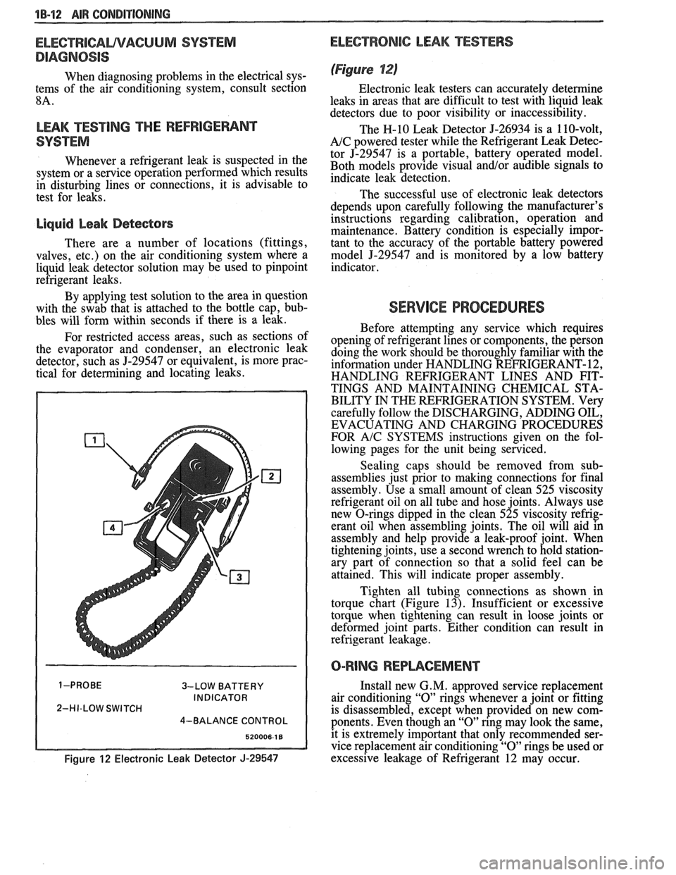
the evaporator and condenser, an electronic leak
detector, such as
5-29547 or equivalent, is more prac-
tical for determining and locating leaks.
3-LOW BATTERY
INDICATOR
2-HI-LOW SWITCH
4-BALANCE CONTROL
Figure 12 Electronic Leak Detector J-29547
ELECTRONIC LEAK TESTERS
(Figure 12)
Electronic leak testers can accurately determine
leaks in areas that are difficult to test with liquid leak
detectors due to poor visibility or inaccessibility.
The H-10 Leak Detector 5-26934 is a 110-volt,
A/C powered tester while the Refrigerant Leak Detec-
tor J-29547 is a portable, battery operated model.
Both models provide visual
and/or audible signals to
indicate leak detection.
The successful use of electronic leak detectors
depends upon carefully following the manufacturer's
instructions regarding calibration, operation and
maintenance. Battery condition is especially impor-
tant to the accuracy of the portable battery powered
model
5-29547 and is monitored by a low battery
indicator.
SERVICE PROCEDURES
Before attempting any service which requires
opening of refrigerant lines or components, the person
doing the work should be thoroughly familiar with the
information under HANDLING REFRIGERANT- 12,
HANDLING REFRIGERANT LINES AND FIT-
TINGS AND MAINTAINING CHEMICAL STA-
BILITY IN THE REFRIGERATION SYSTEM. Very
carefully follow the DISCHARGING, ADDING OIL,
EVACUATING AND CHARGING PROCEDURES
FOR
A/C SYSTEMS instructions given on the fol-
lowing pages for the unit being serviced.
Sealing caps should be removed from sub-
assemblies just prior to making connections for final
assembly. Use a small amount of clean 525 viscosity
refrigerant oil on all tube and hose joints. Always use
new O-rings dipped in the clean 525 viscosity refrig-
erant oil when assembling joints. The oil will aid in
assembly and help provide a leak-proof joint. When
tightening joints, use a second wrench to hold station-
ary part of connection so that
a solid feel can be
attained. This will indicate proper assembly.
Tighten all tubing connections as shown in
torque chart (Figure
13). Insufficient or excessive
torque when tightening can result in loose joints or
deformed joint parts. Either condition can result in
refrigerant leakage.
O-RING REPWCEMENT
Install new G. M. approved service replacement
air conditioning
"0" rings whenever a joint or fitting
is disassembled, except when provided on new com-
ponents. Even though an
"0" ring may look the same,
it is extremely important that only recommended ser-
vice replacement air conditioning
"0" rings be used or
excessive leakage of Refrigerant 12 may occur.
Page 188 of 1825
STEERING LINKAGE 3B6-1
SECTION 3B6
STEERING LINKAGE
The following notice applies to one or more steps in the assembly
procedure of components in this portion of the manual as Notice indicated at
appropriate locations by the terminology "See Caution on Page
1 of this
Section
" .
NOTICE: These fasteners are important attaching parts in that they
could affect the performance of vital components and systems,
andlor could
result in major repair expense. They must be replaced with one of the same
part number or with an equivalent part if replacement becomes necessary. Do
not use a replacement part of lesser quality or substitute design. Torque
values must be used as specified during reassembly to assure proper retention
of these parts. For prevailing torque
nut(s) and bolt(s), refer to the "Reuse of
Prevailing Torque
Nut(s) and Bolt(s)" chart in Section 10.
CONTENTS
General Description ........................................... 3B6- 1 Relay Rod ............................................................ 3B6-3
Maintenance and Adjustments ............................... 3B6- I Idler Arm ............................................................. 3B6-4
On-Car Service ........................................................ 3B6-2 Pitman Arm ......................................................... 3B6-5
Tie Rods .............................................................. 3B6-2 Specifications ........................................................... 3B6-6
GENERAL DESCRIPTION
A parallelogram type steering linkage connects both
steering gear. The right end of the relay rod is supported by
front wheels to the steering gear through the
pitman arm,
the idler arm which pivots on a support attached to the
The right and left tie rods are attached to the steering arms
frame rail. The
pitman arm and idler arm remain parallel to
and to the relay rod by ball studs. The left end of the relay
each other while they move through symmetrical arcs. See
rod is supported by the
pitman arm, which is driven by the Fig. 3B6-2.
MAONTENANCE AND ADJUSTMENTS
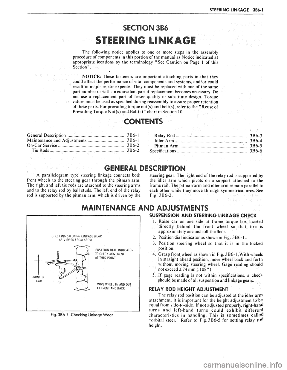
CHELKlNC STtLRING LINKAGE WEIR A? VltlItD FROhl ABOVL
POSITION DIAL INDICATOR
-TO CHECK MOVEMENT
AT THIS POINT
FRONT
OF
MOVE WHEEL IN AND OUT AT FRONT AND BACK
Fig. 3B6-1--Checking Linkage Wear
SUSPENSION AND STEERING LINKAGE CHECK
1. Raise car on one side at frame torque box located
directly behind the front wheel so that tire is
approximately one inch off the floor.
2. Position dial indicator as shown in Fig.
3B6- I .,
3. Position steering wheel so that it is in the locked
position.
4. Grasp front wheel as shown in Fig.
3B6- I. With wheels
in straight ahead position, move wheel back and forth
without moving steering wheel. Gage reading should
not exceed 2.74 mm
(. 108 ").
5. If gage reading is not within specifications, a check
should be made of all suspension and linkage gears.
RELAY ROD HEIGHT ADJUSTMENT
The relay rod position can be adjusted at the idler arm
attach men^. It is important for the height adjustment to be
equal from side-to-side. If not adjusted properly, right-hand
turns and left-hand turns could exhibit differell1
characteristics in handling. This is sometimes called
"orbital steer." Refer to Fig.3B6-5 for setting relay rod
height.
Page 237 of 1825
3E-6 TIRES AND WHEELS
runout of the tire or wheel. Use a dial indicator on the
tire's sidewall and on the rim's flange to determine if
there is excessive lateral
runout.
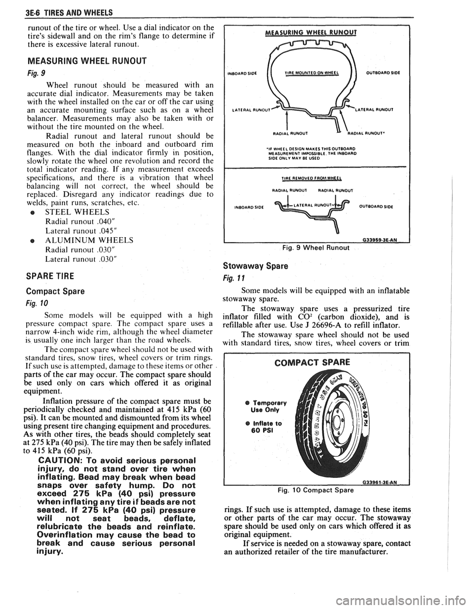
MEASURING WHEEL RUNOUT
Fig. 9
Wheel runout should be measured with an
accurate dial indicator. Measurements may be taken
with the wheel installed on the car or off the car using
an accurate mounting surface such as on a wheel
balancer. Measurements may also be taken with or
without the tire mounted on the wheel.
Radial
runout and lateral runout should be
measured on both the inboard and outboard rim
flanges. With the dial indicator firmly in position,
slowly rotate the wheel one revolution and record the
total indicator reading. If any measurement exceeds
specifications, and there is a vibration that wheel
balancing will not correct, the wheel should be
replaced. Disregard
any indicator readings due to
welds, paint runs, scratches, etc.
e STEEL WHEELS
Radial
runout .040"
Lateral runout .045"
e ALUMINUM WHEELS
Radial
runout .030"
Lateral runout .030"
SPARE TIRE
Compact Spare
Fig. 10
Some models will be equipped with a high
pressure compact spare. The compact spare uses a
narrow 4-inch wide rim, although the wheel diameter
is usually one inch larger than the road wheels.
The compact spare wheel should not be used with
standard tires, snow tires, wheel covers or trim rings.
If such use is attempted, damage to these items or other
parts of the car may occur. The compact spare should
be used only on cars which offered it as original
equipment.
Inflation pressure of the compact spare must be
periodically checked and maintained at
415 kPa (60
psi). It can be mounted and dismounted from its wheel
using present tire changing equipment and procedures.
As with other tires, the beads should completely seat
at
275 kPa (40 psi). The tire may then be safely inflated
to
415 kPa (60 psi).
CAUTION: To avoid serious personal
injury, do not stand over tire when
inflating. Bead may break when bead
snaps over safety hump. Do not
exceed
275 kPa (40 psi) pressure
when inflating any tire
if beads are not
seated. If
275 kPa (40 psi) pressure
will not seat beads, deflate,
relubricate the beads and reinflate.
Overinflation may cause the bead to
break and cause serious personal
injury.
INBOARD SIDE TIRE MOUNTED ON fVHEEL OUTBOARD SIDE
RADIAL
RUNOUT'
'IF WHEEL DESIGN MAKES THISOUTBOARD MEASUREMENT IMPOSSIBLE. THE INBOARD
SIDE ONLY MAY BE USED
I RADIAL RUNOUT RADIAL RUNDUT I
INBOARD SIDE OUTBOARD SIDE
Fig. 9 Wheel Runout
Stowaway Spare
Fig. 11
Some models will be equipped with an inflatable
stowaway spare.
The stowaway spare uses a pressurized tire
inflator filled with
C02 (carbon dioxide), and is
refillable after use. Use
J 26696-A to refill inflator.
The stowaway spare wheel should not be used
with standard tires, snow tires, wheel covers or trim
@ Temporary
Use Only
@ Inflate to 80 PSI
Fig. 10 Compact Spare
rings. If such use is attempted, damage to these items
or other parts of the car may occur. The stowaway
spare should be used only on cars which offered
it as
original equipment.
If service is needed on a stowaway spare, contact
an authorized retailer of the tire manufacturer.
Page 242 of 1825
PROPELLER SHAFT 4A-1
PROPELLER SHAFT
NOTICE: The propeller shaft to pinion flange or slip yoke fasteners are important attaching parts in that
they may affect the performance of vital components and systems, which may result in a major repair expense.
They must be replaced with one of the same part number or with an equivalent part, if replacement becomes
necessary. Do not use a replacement part of lesser quality or substitute design. Torque values must be used as
specified during reassembly to assure proper retention of these parts.
CONTENTS
GENERAL DESCRIPTION ........................ 4A-1
DIAGNOSIS ......................... ............ 4A-1
ON-VEHICLE SERVICE ........................... 4A-I
Propeller Shaft Run-Out
....................................... Measurement 4A- 1
Companion Flange Run-Out
Measurement
............................................. 4A-2
........... Universal Joint Angle Measurement 4A-3
............................ Propeller Shaft Balancing 4A-4
.............................................. Propeller Shaft 4A-8
Removal
.................... .. ............................. 4A-8
GENERAL DESCRIPTION
Figure 4A- I
.............................................. Installation 4A-8
UNIT REPAIR ............................................... 4A-9
Universal Joints
...................... ... ............ 4A-9
....................... Nylon Injected Ring Type 4A-9
..... ....................... Disassembly .... 4A-9
.......................................... Assembly 4A-9
......................... External Snap Ring Type 4A- l 1
............. .................... Disassembly .. 4A- 1 1
........................................... Assembly
4A- 1 1
.................... TORQUE SPECIFICATIONS 4A-12
.................................. SPECIAL TOOLS 4A-12
DIAGNOSIS
Figures 4A-2 and 4A-3
Obiectional vibration, roughness, rumble or
boom
can be caused by the input from a number of
shaft. use a One piece propeller systems. The following diagnostic charts provide a
systematic approach to finding the vehicle problem.
A universal joint and splined slip yoke are located at
the transmission end of the propeller shaft, where they are
held in alignment by a bushing in the transmission exten-
sion housing. The slip yoke permits fore and aft move-
ment of the propeller shaft, as the differential assembly
moves up and down. The spline is lubricated internally by
transmission fluid. A seal in the transmission extension
housing prevents fluid leakage and protects the slip yoke
from dust,
dirt, and other harmful material.
A second universal joint is used where the
propeller shaft connects to the rear axle pinion
companion flange.
The universal joints are lubricated for life and
cannot be lubricated while on the vehicle.
If it becomes
necessary to replace a universal joint, the entire
propeller shaft must be removed from the vehicle. Care
should be taken to avoid jamming, bending or
over-angulating of any parts of the assembly.
On vehicles with steel propeller shafts, production
universal joint bearing caps are retained by nylon injected
rings. Aluminum propeller shafts and all service replace-
ment universal joints use snap rings to retain the bearing
caps.
If a vehicle is to be undercoated, the propeller
shaft must be kept completely free of undercoating
material. Undercoating material or any other foreign
material will upset the propeller shaft balance and
produce serious vibration. To
determine whether the propeller shaft is
causing the problem, drive the vehicle through speed
range and note at which vehicle speed the problem is
most pronounced. Shift the transmission into a lower
gear range and drive the vehicle at the same speed as
when problem was most pronounced.
If the problem is still present at the same vehicle
speed, the propeller shaft may be at fault. Refer to the
propeller shaft diagnostic charts.
ON-VEHICLE SERVICE
PROPELLER SHAFT RUN-OUT MEASUREMENT
Figure 4A-4
If a noise or vibration is present at high speed it
might be caused by a bent shaft, or if a shaft has been
damaged through handling or a collision, it may be
checked for straightness as follows:
1. Raise vehicle on a twin post hoist so that the rear
is supported on the rear axle housing with wheels
free to rotate.
2. Mount
a dial indicator on a movable support that
is high enough to permit contact of the indicator
button with the propeller shaft or mount dial
indicator to a magnetic base and attach to a
suitable smooth place on the underbody of the
vehicle. Readings are to be taken at points
indicated, as shown.
3. With transmission in neutral, check for runout by
turning a rear wheel to rotate the propeller shaft.
Page 264 of 1825
REAR AXLE 4Bl-I I
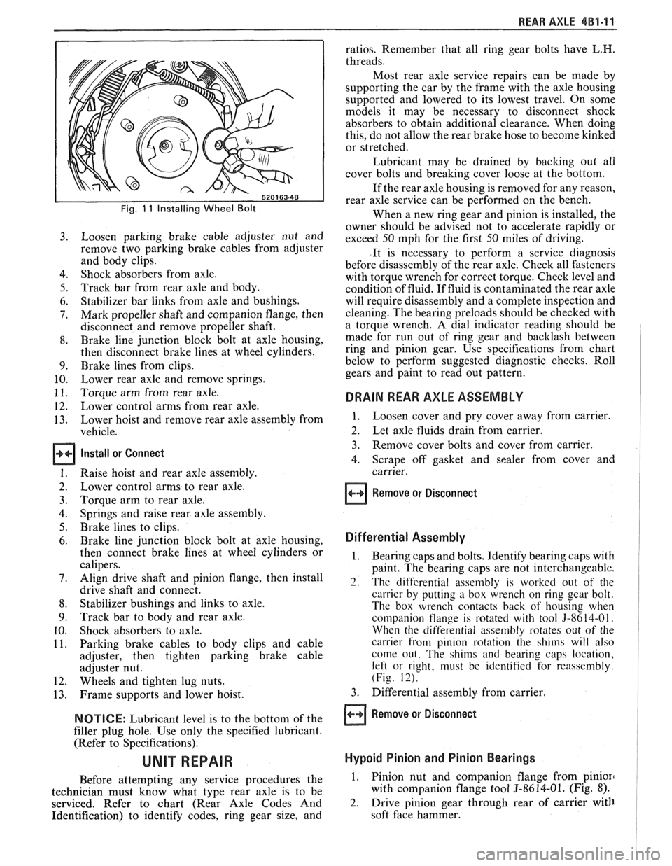
Fig. 11 Installing Wheel Bolt
Loosen parking brake cable adjuster nut and
remove two parking brake cables from adjuster
and body clips.
Shock absorbers from axle.
Track bar from rear axle and body.
Stabilizer bar links from axle and bushings.
Mark propeller shaft and companion flange, then
disconnect and remove propeller shaft.
Brake line junction block bolt at axle housing,
then disconnect brake lines at wheel cylinders.
Brake lines from clips.
Lower rear axle and remove springs.
Torque arm from rear axle.
Lower control arms from rear axle.
Lower hoist and remove rear axle assembly from
vehicle.
Install or Connect
Raise hoist and rear axle assembly.
Lower control arms to rear axle.
Torque arm to rear axle.
Springs and raise rear axle assembly.
Brake lines to clips.
Brake line junction block bolt at axle housing,
then connect brake lines at wheel cylinders or
calipers.
Align drive shaft and pinion flange, then install
drive shaft and connect.
Stabilizer bushings and links to axle.
Track bar to body and rear axle.
Shock absorbers to axle.
Parking brake cables to body clips and cable
adjuster, then tighten parking brake cable
adjuster nut.
Wheels and tighten lug nuts.
Frame supports and lower hoist.
NOTICE: Lubricant level is to the bottom of the
filler plug hole. Use only the specified lubricant.
(Refer to Specifications).
Before attempting any service procedures the
technician must know what type rear axle is to be
serviced. Refer to chart (Rear Axle Codes And
Identification) to identify codes, ring gear size, and ratios.
Remember that all ring gear bolts have
L.H.
threads.
Most rear axle service repairs can be made by
supporting the car by the frame with the axle housing
supported and lowered to its lowest travel. On some
models it may be necessary to disconnect shock
absorbers to obtain additional clearance. When doing
this, do not allow the rear brake hose to become
kinked
or stretched.
Lubricant may be drained by backing out all
cover bolts and breaking cover loose at the bottom.
If the rear axle housing is removed for any reason,
rear axle service can be performed on the bench.
When a new ring gear and pinion is installed, the
owner should be advised not to accelerate rapidly or
exceed 50 mph for the first 50 miles of driving.
It is necessary to perform a service diagnosis
before disassembly of the rear axle. Check all fasteners
with torque wrench for correct torque. Check level and
condition of fluid.
If fluid is contaminated the rear axle
will require disassembly and a complete inspection and
cleaning. The bearing preloads should be checked with
a torque wrench. A dial indicator reading should be
made for run out of ring gear and backlash between
ring and pinion gear. Use specifications from chart
below to perform suggested diagnostic checks. Roll
gears and paint to read out pattern.
DRAIN REAR AXLE ASSEMBLY
1. Loosen cover and pry cover away from carrier.
2. Let axle fluids drain from carrier.
3. Remove cover bolts and cover from carrier.
4. Scrape off gasket and sealer from cover and
carrier.
Remove or Disconnect
Differential Assembly
1. Bearing caps and bolts. Identify bearing caps with
paint. The bearing caps are not interchangeable.
2. The differential assembly is worked out of the
carrier by putting a box wrench on ring gear bolt.
The box wrench contacts back of housing when
companion
tlange is rotated with tool 3-8614-01.
When the differential assembly rotates out of the
carrier from pinion rotation the shims will also
come out. The shims and bearing caps location,
left or right, must be identified for reassembly.
(Fig. 12).
3. Differential assembly from carrier.
Remove or Disconnect
Hypoid Pinion and Pinion Bearings
1. Pinion nut and companion flange from pinion
with companion flange tool 5-8614-01. (Fig. 8).
2. Drive pinion gear through rear of carrier with
soft face hammer.