1988 PONTIAC FIERO service indicator
[x] Cancel search: service indicatorPage 1131 of 1825
7A1-12 AUTOMATIC TRANSMISSION ON-VEHICLE SERVICE
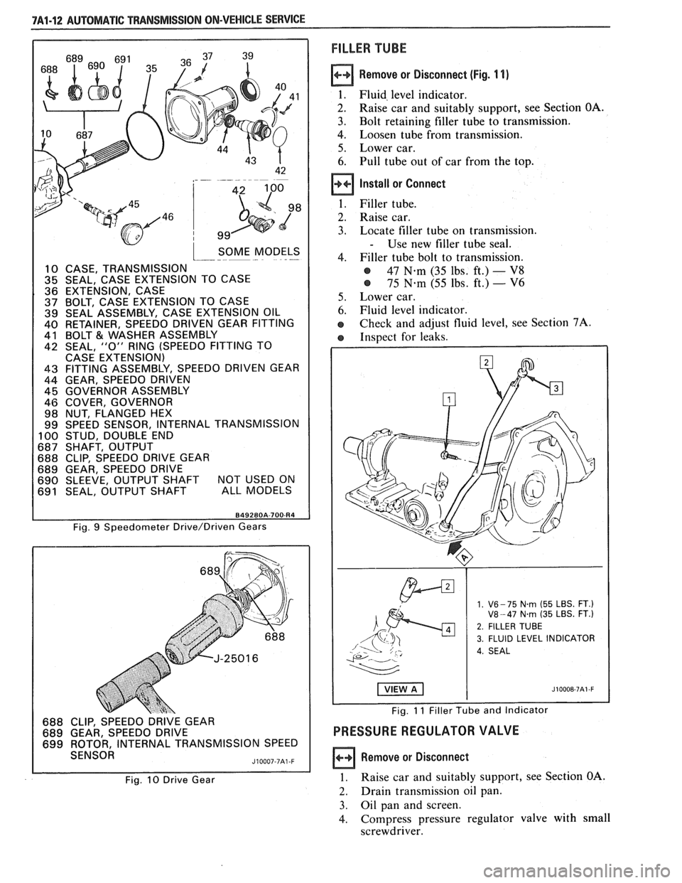
SOME MODELS I--- - .-
10 CASE, TRANSMISSION 35 SEAL, CASE EXTENSION TO CASE
36 EXTENSION, CASE 37 BOLT, CASE EXTENSION TO CASE 39 SEAL ASSEMBLY, CASE EXTENSION OIL 40 RETAINER, SPEEDO DRIVEN GEAR FITTING
41 BOLT €31 WASHER ASSEMBLY 42 SEAL, "0" RING (SPEEDO FITTING TO
CASE EXTENSION)
43 FITTING ASSEMBLY, SPEEDO DRIVEN GEAR
44 GEAR, SPEEDO DRIVEN 45 GOVERNOR ASSEMBLY
46 COVER, GOVERNOR
98 NUT, FLANGED HEX
99 SPEED SENSOR, INTERNAL TRANSMISSION
100 STUD, DOUBLE END 687 SHAFT, OUTPUT 688 CLIP, SPEEDO DRIVE GEAR
689 GEAR, SPEEDO DRIVE
690 SLEEVE, OUTPUT SHAFT NOT USED ON 691 SEAL, OUTPUT SHAFT ALL MODELS
FILLER TUBE
Remove or Disconnect (Fig. 1 1)
1. Fluid, level indicator.
2. Raise car and suitably support, see Section OA.
3. Bolt retaining filler tube to transmission.
4. Loosen tube from transmission.
5. Lower car.
6. Pull tube out of car from the top.
Install or Connect
1. Filler tube.
2. Raise car.
3. Locate filler tube on transmission.
- Use new filler tube seal.
4. Filler tube bolt to transmission.
@ 47 N.m (35 lbs, ft.) - V8
@ 75 N-m (55 lbs. ft.) - V6
5. Lower car.
6. Fluid level indicator.
e Check and adjust fluid level, see Section 7A.
e Inspect for leaks.
Fig. 9 Speedometer Drive/Driven Gears
688 CLIP, SPEEDO DRIVE GEAR
689 GEAR, SPEEDO DRIVE
699 ROTOR, INTERNAL TRANSMISSION SPEED
SENSOR
J10007-7A1 -F
Fig. 10 Drive Gear
1. V6- 75 N.rn (55 LBS. FT.) V8-47 N.rn (35 LBS. FT.)
2. FILLER TUBE
3. FLUID LEVEL INDICATOR
4. SEAL
Fig. 11 Filler Tube and Indicator
PRESSURE REGULATOR VALVE
Remove or Disconnect
1. Raise car and suitably support, see Section OA.
2. Drain transmission oil pan.
3. Oil pan and screen.
4. Compress
pressure regulator valve with small
screwdriver.
Page 1135 of 1825
7Al-16 AUWBMATIC TWANSMIS810N ON-VEHICLE SERVICE
line at the cooler and observe the flow with the
engine running.
@ Insufficient flow: inspect cooler pipes, fit- 5.
tings and repeat cooler flushing proce-
dure. If the flow is still insufficient,
replace the cooler.
21. Remove the discharge hose and reconnect the
cooler pipe. Adjust fluid level as needed. 7.
8.
9.
TRANSMISSION ASSEMBLY 10.
Figs. 73 tkru 1 7
A pressure test should be performed before
transmission removal to aid in diagnosis.
Tools Required:
J 21366 Torque Converter Holding Fixture
Remove or Disconnect
1. Negative battery cable.
2. Air cleaner.
3. T.V.
cable at throttle lever.
4. Transmission fluid level indicator.
5. Raise
car and suitably support, see Section
OA.
6. Speedometer cable.
7. Shift control cable.
8. Electrical leads at transmission.
9. Flexplate cover.
e Mark flywheel to torque converter.
10. Torque converter bolts.
11. Torque arm, see Section 3D.
12. Propeller shaft, see Section
48.
13. Support transmission.
14. Crossmember and mount bolts.
15. Oil cooler pipes at transmission.
16. T.V. cable at transmission.
17. Transmission to engine bolts.
18. Transmission.
a Install J 21366 and remove transmission.
Clean
Transmission oil cooler and lines
should be Flushed with
J35944 or
equivalent whenever the transmission
has
been removed for overhaul or re-
placement of the torque converter,
pump or case.
Install or Connect
1. Attach transmission jack.
2. Raise transmission.
- Remove J 21 366
3. Transmission to engine bolts.
- 44N.m(35 Ibs. ft.)
4. Crossmember, mount and bolts.
- Crossmember to body.
- 54 N .m (40 lbs. ft.)
- Mount to crossmember.
- 44 W-m (35 lbs. ft.)
- Mount to transmission.
- 54 N-m (40 Ibs. ft.)
Torque converter to flexplate bolts.
- 47 N-m (35 lbs, ft.)
- Align marks made during disassembly,
- Flexplate cover.
Oil cooler lines.
T.V. cable.
Electrical leads at transmission.
Speedometer cable.
Shift control cable.
11. Propeller shaft, see Section 4A.
12. Torque arm, see Section 3D.
13. Lower car.
14.
T.V. cable at throttle lever.
15. Negative battery cable.
16. Air cleaner.
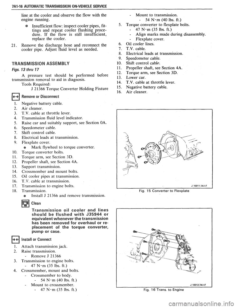
Fig. 15 Converter to Flexplate
Fig.
16 Trans. to Engine
Page 1167 of 1825
Page
Air Conditioning
Air Delivery
Electronic
.................... 68-0
Manual
....................... 65-0
Blower Controls
Electronic
.................... 66-0
Manual
....................... 63-0
Compressor Controls Electronic
.................... 67-0
Manual
....................... 64-0
................... System Check 62-0
Alarms (Audible)
Chime
......................... 77-0
Antenna(Power) ................... 151-0
Brakes
................. Warning System 41-0
................... Charging system 30-7
...................... Cigar Lighter 114-0
Circuit Breaker Details
PWR ACC Circuit
.......... Breaker 10.1.10.3.10.5.1 1.3
WDO Circuit Breaker
10.1. 10.3. 10.5. 11-4
.......... Component Location Views 201-0
Connectors (Harness Connector Faces) 202-0
el00 .......................... 202-0
............... Junction Block ((2238) 202-2
Coolant Fan
....................... 31-0
Cruise Control
..................... 34-0
Defogger
......................... 61-0
Digital Clock
...................... 150-0
Displays Digital Cluster
.................. 82-0
Coolant Temperature
........... 82-2
Page
......................... Fuel 82-3
................... Oil Pressure 82-2
.................. Speedometer 82-3
................. Door Locks (Power) 130-0
...... Driver Information Center (DIC) 86-0
Engines
... Multi-Port Fuel Injection (VIN S) 20-0
.... Multi-Port Fuel Injection (VIN 8) 23-0
.... Throttle
Body Injection (VIN E) 22-0
...... Tuned
Port Injection (VIN F) 21-0
................. Fuse Block Details 11-0
Fuse Details
........... INST LP 10.0.10.2.10.4.1 1.1
.............. TAIL 10.0.10.2.10.4.1 1.2
................ CRANK 10.0.10.2.1 0.4
.............. CTSY 10~0.10.2.10.4.1 1.2
......... STOP HAZ 10.1.10.3.10.5.1 1.3
............ RADIO 10.1.10.3.10.5.1 1.4
............ WIPER 10.1.10.3.10.5.1 1.4
.................... HATCH 10.2.1 0.4
........... HTR AlC 10.1.10.3.10.5.1 1.4
........... CIH.FAN 10.1.10.3.10.5.1 1.4
......... TURN BIU 10.1.10.3.10.5.1 1.4
............ GAGES 10.1.10.3.10.5.1 1.4
ECM-IGN
(V6 VIN S. V8 VIN F.
........ V8 VIN 8. V8 VIN E) 10.1.1 1.7
............ INJ 1 (V6 VIN S) 10.1.1 1.10
......... FPIINJ 2 (V6 VIN S) 10.1.1 1.10
... INJ 1 (V8 VIN F. V8 VIN 8) 10.3.1 1.11
FPIINJ 2 (V8 VIN F. V8 VIN 8) 10.3.1 1.11
............ CLSTR 10.1.10.3.10.5.1 1.13
............. FPIINJ 2 (V8 VIN E) 11-12
Page
Gages
................... Gages Cluster 81-0
........... Coolant Temperature 81-2
......................... Fuel 81-3
................... Oil Pressure 81-2
.................. Speedometer 81-3
................ Ground Distribution 14-0
Harness Routing Views
............. 203-0
........................... Heater 60-0
............................ Horns 40-0
Indicators
.................. Digital Cluster 82-0
................ Brake Warning 82-4
.................. Fasten Belts 82-1
...................... Hi Beam 82-1
...................... Security 82-1
............ Service Engine Soon 82-4
......................... Shift 82-5
......................... Turn 82-1
................... Gages Cluster 81-0
................ Brake Warning 81-0
.................. Fasten Belts 81-0
...................... Hi Beam 81-0
............ Service Engine Soon 81-0
......................... Shift 81-1
......................... Turn 81-0
Instrument Panel
Digital Cluster
.................. 82-0
Gages Cluster
................... 81-0
............ Interior Lights Dimming 117-0
...................... Introduction 2-0
Lights (Exterior)
........................ Back Up 112-0
...................... Fog 100.3,10 3.0
Page 1271 of 1825
THROTTLE BODY INJECTION: V8 VIN E IF
IGNITION, SERVICE ENGINE SOON INDICATOR, AND TACHOMETER
Page 1283 of 1825
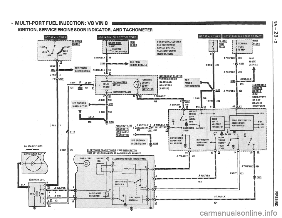
-. MULTI-PORT FUEL INJECTION: V8 VIN 8 I F w
IGNITION, SERVICE ENGINE SOON INDICATOR, AND TACHOMETER I
Page 1318 of 1825
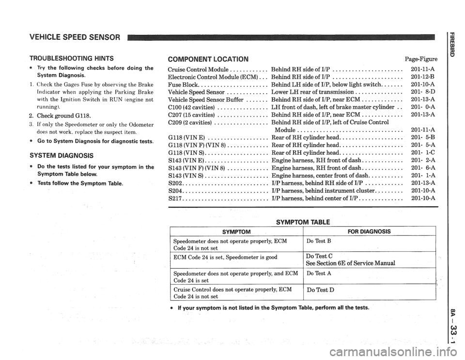
VEHICLE SPEED SENSOR
TROUBLESHOOTING HINTS
0 Try the following checks before doing the
System Diagnosis
.
1
. Check the Gages Fuse by observing the Brake
Indicator when applying the Parking Brake
wrth the Ignition Switch in RUN (engine not
running)
.
2 . Check ground 6118 .
3 . If only the Speedometer or only the Odometer
does not work. replace the suspect item
.
Go to System Diagnosis for diagnostic tests .
SYSTEM DlAGNOSlS
Do the tests listed for your symptom in the
Symptom Table below
.
Tests follow the Syrnptom Table .
COMPONENT LOCATION Page-Figure
Cruise Control Module
............ Behind RN side of IlP ...................... 201-11-A
Electronic Control Module (ECM)
... Behind RN side of IIP ...................... 201-12-B
Fuse Block
...................... Behind LN side of IIP. below light switch ....... 201-10-A
Vehicle Speed Sensor
............. Lower LEI rear of transmission ............... 201- 8-D
Vehicle Speed Sensor Buffer
....... Behind RH side of IIP. near ECM ............. 201-13-A
ClOO (42 cavities) ................ LN front of dash. left of brake master cylinder .. 201- 0-A
C207 (15 cavities) ................ Behind RH side of IIP. near ECM ............. 201-13-A
C209 (2 cavities)
................. Behind RN side of IIP. left of Cruise Control
................................. Module 201-11-A
6118 (VIN E)
................... Rear of RH cylinder head .................... 201- 5-B
6118 (VIN F) (VIN 8) ............. Rear of RN cylinder head .................... 201- 5-A
6118 (VIN S)
.................... Rear of RN cylinder head .................... 201- 1-C
S143 (VINE)
.................... Engine harness. RH front of dash ............. 201- 2-A
S143 (VIN F) (VIN
8) ............. Engine harness. RN front of dash ............. 201- 6-A
S143 (VIN S)
.................... Engine harness. center front of dash ........... 201- 1-A
S202
........................... IIP harness. behind RH side of IIP ............ 201-13-A
S204
........................... IIP harness. behind instrument cluster ......... 201-10-A
S217 ........................... IIP harness. behind center of IIP .............. 201-10-A
SYMPTOM TABLE
I SYMPTOM I FOR DIAGNOSIS I
=liter does not operate properly. ECM I Do Test B
code 24 is not set
ECM Code
24 is set. Speedometer is good
e If your symptom is not listed in the Symptom Table. pedorm all the tests .
Do Test C
See Section 6E of Service Manual
Speedometer does not operate properly. and ECM
Code
24 is set
Cruise Control does not operate properly. ECM
Code
24 is not set Do
Test
A
Do Test D
Page 1334 of 1825
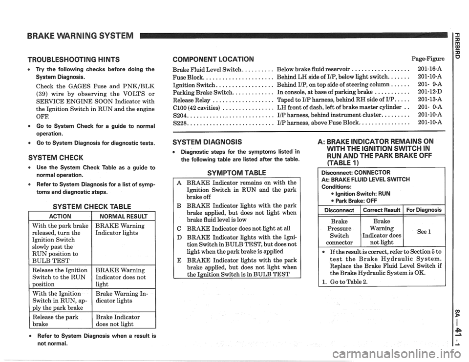
BRAKE VVARNlNG SYSTEM
TROUBLESHOOTING HINTS
0 Try the following checks before doing the
System Diagnosis.
Check the GAGES Fuse and PNKIBLK
(39) wire by observing the VOLTS or
SERVICE ENGINE SOON Indicator with
the Ignition Switch in RUN and the engine
OFF.
0 Go to System Check for a guide to normal
operation.
0 Go to System Diagnosis for diagnostic tests.
SYSTEM CHECK
Use the System Check Table as a guide to
normal operation.
e Refer to System Diagnosis for a list of symp-
toms and diagnostic steps.
SYSTEM CHECK TABLE
RUN position to
BULB TEST
COMPONENT LOCATION Page-Figure
.................. Brake Fluid Level Switch. ......... Below brake fluid reservoir 201-16-A
..................... Fuse Block. Behind
LH side of IIP, below light switch. ...... 201-10-A
................. Ignition Switch. Behind IIP, on
top side of steering column ...... 201- 9-A
Parking Brake Switch.
............ In console, at base of parking brake ........... 201-12-D
................... Release Relay Taped
to IIP harness, behind RH side of IIP. .... 201-13-A
................ (2100 (42 cavities) LR
front of dash, left of brake master cylinder .. 201- 0-A
........................... S204. IIP harness, behind instrument cluster. ........ 201-10-A
.......................... ............... S228. IIP harness, above Fuse Block. 201-10-A
SYSTEM DIAGNOSIS
0 Diagnostic steps for the symptorns listed'in
the following table are listed after the table.
A: BRAKE INDICATOR REMAINS ON
WITH THE
IGNITION SWITCH IN
RUN AND THE PARK BRAKE OFF
(TABLE
1)
SYMPTOM TABLE
A BRAKE Indicator remains on with the
Ignition Switch
in RUN and the park
brake off
B BRAKE Indicator lights with the park
brake applied, but does not light when
brake fluid level is low
C BRAKE Indicator does not light at all
D BRAKE Indicator lights with the Igni-
tion Switch in BULB TEST, but does not
light when the park brake is applied
E BRAKE Indicator lights with the park
brake applied, but does not light when
the Ignition Switch is in BULB TEST
Refer to System Diagnosis when a result is
not normal. Disconnect:
CONNECTOR
At: BRAKE FLUID LEVEL SWITCH
Conditions:
0 Ignition Switch: RUN
0 Park Brake: OFF
Pressure Warning
If the result is correct, refer to Section
5 to
test the Brake Hydraulic System.
Replace the Brake Fluid Level Switch if
the Brake Hydraulic System is OK.
1. Go to Table2.
Page 1342 of 1825
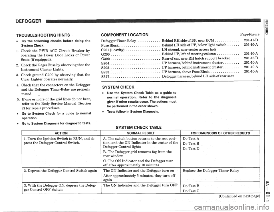
DEFOGGER
TROUBLESHOOTING HINTS
e Try the following checks before doing the
System Check.
1. Check the PWR ACC Circuit Breaker by
operating the Power Door Locks or Power
Seats (if equipped).
2. Check the Gages Fuse by observing that the
Instrument Cluster Lights.
3. Check ground 6200 by observing that the
Cigar Lighter operates normally.
4. Check that the connectors on the Defogger
and the Defogger Timer-Relay are properly
mated.
5. If one or more of the grid lines do not heat,
refer to the Body Service Manual (Section
2) for repair procedures.
e Go to System Check for a guide to normal
operation.
a Go to System Diagnosis for diagnostic tests.
COMPONENT LOCATION Page-Figure
............ ............. Defogger Timer-Relay Behind
RH side of IIP, near ECM 201-1 1-D
..................... Fuse Block. Behind LH side
of I/P, below light switch. ...... 201-10-A
.................. 6201 (1 cavity) LH
shroud, near center access hole
.......................... 6200 Behind IIP, left of steering column ............ 201-10-16
.......................... 6322 Rear of car, near RH hatch support bracket. .... 201-15-D
.......................... S204. IIP harness, behind instrument cluster. ........ 201-10-A
.......................... S205. IIP harness, behind instrument cluster. ........ 201-10-A
.......................... S233. IIP harness, above Fuse Block. ............... 201-10-A
.......................... S327. Defogger harness, behind LR side of rear seat
SYSTEM CHECK
e Use the System Check Table as a guide to
normal operation. Refer to the diagnosis
given if other results occur. The actions must
be
pedormed in the order shown.
Tests follow in System Diagnosis.
SYSTEM CHECK TABLE -- -
ACTION NORMAL RESULT FOR DIAGNOSIS OF OTHER RESULTS
1. Turn the Ignition Switch to RUN, and de-
press the Defogger Control Switch.
2. Depress the Defogger Control Switch again
3. With the Defogger ON, depress the Defog-
ger Control OFF Switch
I
A. The switch button returns to the rest posi-
tion, and the ON Indicator in the center of the
Defogger Control lights
B. The Defogger grid removes fog from the
rear window
C. The ON Indicator and the Defogger turn
off after approximately
10 minutes
The ON Indicator and the Defogger turn on
After approximately
5 minutes, they turn off
again
The ON Indicator and the Defogger turn OFF Do
Test A
Do Test B
Do Test D
Replace the Defogger Timer-Relay
Do Test B
(Continued on next page)