1988 PONTIAC FIERO service indicator
[x] Cancel search: service indicatorPage 1344 of 1825
DEFOGGER
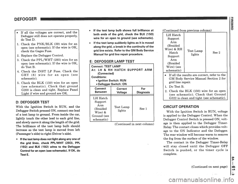
r If all the voltages are correct, and the
Defogger still does not operate properly,
do Test D.
1. Check the PNK/BLK (39) wire for an
open (see schematic). If the wire is OK,
check the Gages Fuse.
2. Replace the Defogger Control.
3. Check the PPL/WHT (293) wire for an
open (see schematic). If the wire is OK,
do Test B.
4. Check the INST LP Fuse. Check the
GRY
(8) wire for an open (see
schematic).
5. Check the BLK (150) wire for an open
(see schematic). Check that ground
6200 is clean and tight. Replace Panel
Light if wire and ground are OK.
D: DEFOGGER TEST
With the Ignition Switch in RUN, and the
Defogger Switch pressed
ON, connect one lead
of a test lamp to ground. From inside the car,
lightly touch the other lead to each grid line,
and slowly move it along the length of the grid.
The brilliance of the test lamp bulb should
increase as the test lamp is moved from left
(Passenger's side) to right (Driver's side).
0 If the test lamp does not light along any one of
the grid lines, check
PPLIWHT (2931, PPL
(192) and BLK (192) wires to the Defogger
Control for an open
(see schematic). If OK, do
Test
E.
If the test lamp bulb shows full brilliance at
both ends of the grid, check the BLK
(1 50)
wire for an open to ground (see schematic).
e If the test lamp suddenly lights as it is moved
along the grid, a break in the continuity of the
grid line exists. Refer to the
GM Body Service
Manual for grid line repair procedure.
E: DEFOGGER LAMP TEST
CH SUPPORT ARM
Ignition Switch: RUN
LH Hatch
Support Arm
(Braided Test
Lamp
lights See
1
Wire) &
Ground
(see
schematic)
(Continued in next column) (Continued
from previous column)
See 2
Arm
(Braided
Wire) (see
schematic)
I
If all the results are correct, refer to the
GM Body Service Manual Section 2 for
grid line repair.
1. Do Test B.
2. Check the BLK (150) wire for an open
(see schematic). Check that Ground
6322 is clean and tight (see schematic).
CIRCUIT OPERATION
With the Ignition Switch in RUN, voltage
is applied to the Defogger Control. When the
Defogger Control Switch is pressed ON, volt-
age is then applied to the Defogger
Timer-
Relay. The contact closes which provides volt-
age to the ON Indicator and the Defogger.
The rear window will become warm to remove
the fog from the surface of the window.
The contact in the Defogger Timer-Relay
will stay closed until the Defogger OFF
Switch is pushed, or the timer cycle is
complete.
(Continued on next page)
Page 1403 of 1825
INSTRUMENT PANEL: GAGES CLUSTER I e
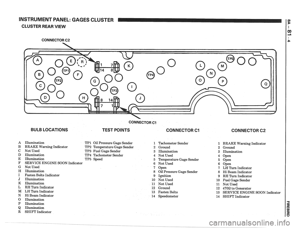
CLUSTER REAR VIEW
CONNECTOR 62
-
BULB LOCATIONS
CONNECTOR Cl
TEST POINTS CONNECTOR Cl
A Illumination TP1 Oil Pressure Gage Sender 1
B BRAKE Warning Indicator TP2 Temperature Gage Sender 2
C Not Used TP3 Fuel Gage Sender 3
D Illumination TP4 Tachometer Sender 4
E Illumination TP5 Speed 5
F SERVICE ENGINE SOON Indicator
6
G Not Used 7
H Illumination 8
I Fasten Belts Indicator 9
J Illumination 10
K Illumination 11
L RH Turn Indicator 12
M LH Turn Indicator 13
N Hi Beam Indicator 14
O Illumination
P Illumination
Q Illumination
R SHIFT Indicator Tachometer Sender
Ground
Illumination
Not Used
Temperature Gage Sender
Not Used
Open
Oil Pressure Gage Sender
Ignition
Not Used
Not Used
Ground
Fasten Belts
Speedometer
CONNECTOR 62
1 BRAKE Warning Indicator
2 Ground
3 Illumination
4 Open
5 Open
6 Open
7 LH Turn Indicator
8 Hi Beam Indicator
9 RH Turn Indicator
10 Fuel Gage Sender
11 Not Used
12
470R to Generator
13 SERVICE ENGINE SOON Indicator
14 SHIFT Indicator
Page 1406 of 1825
INSTRUMENT PANEL: GAGES CLUSTER
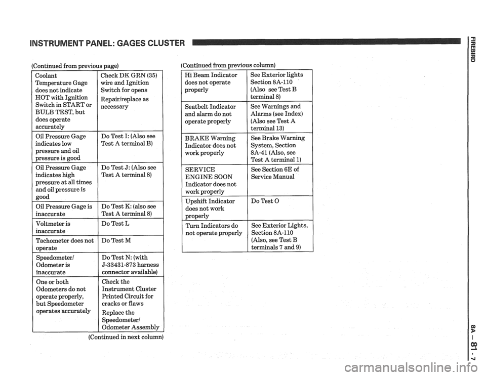
I Oil Pressure Gage
(Continued from previous page)
indicates low
pressure
and oil
pressure is good
Coolant
Temperature Gage
does not indicate
HOT with Ignition
Switch in START or
BULB TEST, but
does operate
accurately
Do Test I: (Also see
Test A
terminal B)
Check DK GRN (35)
wire and Ignition
Switch for opens
Repairlreplace as
necessary
Oil Pressure Gage
indicates high
pressure at
all times
and oil pressure is
good Do
Test
J: (Also see
Test A terminal
8)
Oil Pressure Gage is
inaccurate Do
Test K: (also see
Test A terminal
8)
Do Test L
Tachometer does not
operate
Speedometer1
Odometer is
inaccurate Do
Test M
Do Test N: (with
5-33431-873 harness
connector available)
One or both
Odometers do not
operate properly,
but Speedometer
operates accurately
I
Check the
Instrument Cluster
Printed Circuit for
cracks or flaws
Replace the
Speedometer1
Odometer Assembly
(Continued in next column) (Continued from previous
column)
Hi Beam Indicator
does not operate
properly See
Exterior lights
Section 8A-110
(Also see Test
B
terminal 8)
I operate properly
I
(Also see Test A
I
Seatbelt Indicator
and alarm do not
BRAKE Warning Indicator does not
work properly
I
See Warnings and
Alarms (see Index)
SERVICE
ENGINE SOON
Indicator does not
does not work See
Brake Warning
System, Section
8A-41 (Also, see
Test A terminal
1)
See Section 6E of
1 Service Manual
Do Test O
r
(Also, see Test B
terminals 7 and
9)
Page 1601 of 1825
88-2 LIGHTING SYSTEMS AND HORNS
The fog lights must be aimed for proper
illumination of the road. Fog light
aim should be
checked: at least once a year; when a new light housing
is installed; or if service or repairs in the front end area
have (or may have) disturbed the fog light mountings.
FRONT PARKING/TURM SIGNAL
LIGHTS - Pushing either side of the instrument panel
switch will turn on the front parking lights. (Pushing
the left side of the switch will also turn on the
headlights.) When the ignition is on and the turn signal
lever is moved, the appropriate front parking light
flashes to signal a turn. Both lights will flash when the
hazard flashers are on.
If the driver's door is opened when the parking
lights are on, a warning tone will sound. For more
information, see Section
8A-77.
HAZARD FLASHERS - The hazard warning
flasher is part of the turn signal circuit. Pushing in the
button (on the right side of the steering column) will
cause the front and rear turn signal lights, and the front
sidemarker lights, to flash. Pull out the collar around
the button to turn off the hazard flashers.
The hazard flashers will work with the ignition
either off or on. When the hazard flashers are on, the
turn signals do not
work.
The hazard flashers will stop flashing and stay on
brightly if the brake pedal is pushed down.
HEADLIGHTS - The headlights are controlled
by the switch on the instrument panel (to the left of the
speedometer). They will come on whether or not the
ignition is turned on. Pushing the upper left side of the
switch turns on the headlights and causes the headlight
motors to raise the headlights. Pushing the bottom part
of the switch turns off the headlights, and they should
lower.
If the driver's door is opened when the ignition
is off and the headlights are on, a warning tone will
sound. For more information, see Section
8A-77.
Headlight low-beam and high-beam are
controlled by the turn
signal/multifunction lever on
the left side of the steering column. When the
headlights are on, pull the lever toward the steering
wheel until the switch clicks; the lights will change
from low-beam to high-beam, or from high-beam to
low-beam. An indicator light on the center instrument
cluster will come on when the high-beam headlights
are on.
The headlights must be aimed for proper
illumination of the road. Headlight aim should be
checked: at least once a year; when a new headlight
bulb is installed; or if service or repairs in the front end
area have (or may have) disturbed the headlights or
their mountings. The headlight bezels do not need to
be removed to aim the headlights.
Headlight focus is set when the sealed-beam unit
is made; no adjustment for focus is necessary or
possible.
Some state and local laws specify
requirements for headlight aim; these laws
must be followed.
LICENSE PLATE LBGHTS -A light above the
rear license plate will come on when the headlights or
parking lights are on.
LIGHT SWITCH - Most exterior lights are
controlled by the switch on the instrument panel, to the
left of the speedometer. Pushing the upper right part
of the switch turns on the front parking lights, the
taillights and the sidemarker lights. (It also turns on
the instrument panel lights.) Pushing the upper left
part of the switch turns on all these lights plus the
headlights. Pushing the bottom part of the switch turns
off all lights.
In some cases (such as going through a car wash),
it may be desirable to raise the headlights without
leaving the headlights on. To do so, push the upper
right part of the switch to turn on the parking lights.
Then, lightly push the upper right part of the switch;
the headlights will raise but will not turn on.
(Remember that the parking lights and taillights will
stay on.)
For more information on this switch (including
on-car service), see Section
8C. Also see Section 8C for
information on interior lights.
REAR TAlL/STOP/TURN SIGNAL
LIGHTS - The rear tail/stop/turn signal lights are
part of the same light assembly. Pushing either side of
the instrument panel switch turns on the taillights.
When the brake pedal is pushed down, the lights glow
brighter to serve as stoplights.
Moving the turn signal lever when the ignition is
on causes the appropriate rear lights to flash. (If the
brake pedal is held down and a turn is signalled, one
side will flash and the other will stay on brightly.)
All lights will flash when the hazard flashers are
on. However, if the brake pedal is pushed while the
hazard flashers are on, the lights will stop flashing and
stay on brightly.
SIDEMARKER LIGHTS -The front and rear
sidemarker lights will come on when the headlights or
parking lights are on. Both front and rear sidemarker
lights also have reflectors; they will shine when struck
by light, whether or not the car's lights are on.
If the headlights or parking lights are off when a
turn is signalled, the front sidemarker light will flash
in unison with the front turn signal light on the same
side. If the lights are on when a turn is signalled, the
front
sidemarker light and front turn signal light flash
alternately.
TURN SlG N ALS - The front turn signals are
combined with the front parking lights. The rear turn
signals are part of the rear
tail/stop/turn signal lights.
The turn signals work only when the ignition is on, and
the hazard flashers are turned off.
The turn signals are controlled by the turn
signal/multifunction lever on the left side of the
steering column. Moving the lever all the way up or
down (past the detent) will turn on the turn signals.
When the turn is completed, the lever will return to
neutral and the turn signals will stop flashing.
For changing lanes or shallow turns where the
steering wheel does not move far enough to cancel the
signal, move the turn signal lever only to the first
detent. When the lever is released, it will return to
neutral and the turn signals will cancel.
UNDERHOOD LIGHT - The underhood light
will come on when the hood is raised.
Page 1609 of 1825
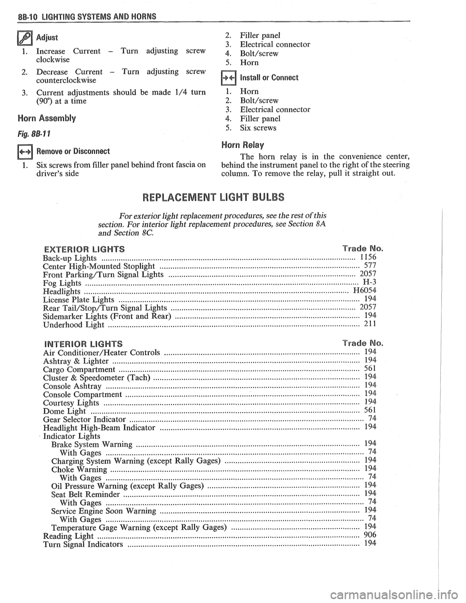
Adjust 2 . Filler panel 3 . Electrical connector
1 . Increase Current - Turn adjusting screw 4 . ~~l~/~~~~~
clockwise 5 . Horn
2 . Decrease Current . Turn adjusting screw
counterclockwise
Install or Connect
3 . Current adjustments should be made 1/4 turn
(90") at a time
Horn Assembly
Remove or Disconnect
1 . Six screws from filler panel behind front fascia on
driver's side 1
. Horn
2 . Bolt/screw
3 . Electrical connector
4
. Filler panel
5 . Six screws
Horn Relay
The horn relay is in the convenience center.
behind the instrument panel to the right of the steering
column
. To remove the relay. pull it straight out .
REPLACEMENT LIGHT BULBS
For exterior light replacement procedures. see the rest of this
section
. For interior light replacement procedures. see Section $A
and Section 8C .
EXTERIOR LIGHTS Trade No . ...................................................................................................................... Back-up Lights 1 156
Center
High-Mounted Stoplight ............................................................................................. 577
Front Barking/Turn Signal Eights ..................................................................................... 2057
Fog Lights
............................................................................................................................... H-3
Headlights ....................................................................................................................... H6054 ................................................................................................................ License Plate Lights 194
.................................................................................... Rear Tail/Stop/Turn Signal Lights 2057
Sidemarker Lights (Front and Rear) ...................................................................................... 194 ..................................................................................................................... Underhood Light 211
BNTERBOR LIGHTS Trade No .
......................................................................................... Air Conditioner/Heater Controls 194 .................................................................................................................. Ashtray & Lighter 194 .............................................................................................................. Cargo Compartment 561
................................................................................................ Cluster & Speedometer (Tach) 194 ..................................................................................................................... Console Ashtray 194 ............................................................................................................. Console Compartment 194
Courtesy Lights
..................................................................................................................... 194 ......................................................................................................................... Dome Light 561
Gear Selector Indicator
............................................................................................................ 74 .......................................................................................... Headlight High-Beam Indicator 194
Indicator Lights
..................................................................................................... Brake System Warning 194
With Gages
........................................................................................................................ 74
............................................................... Charging System Warning (except Rally Gages) 194 .................................................................................................................... Choke Warning
194
With Gages
........................................................................................................................ 74
...................................................................... Oil Pressure Warning (except Rally Gages) 194 ............................................................................................................ Seat Belt
Reminder 194
With Gages
.................................... ... ................................................................................. 74 ............................................................................................. Service Engine Soon Warning 194
With Gages
..................................................................................................................... 74 ............................................................ Temperature Gage Warning (except Rally Gages) 194
........................................................................................................................ Reading
Light 906 ............................................................................................................ Turn Signal Indicators 194
Page 1612 of 1825
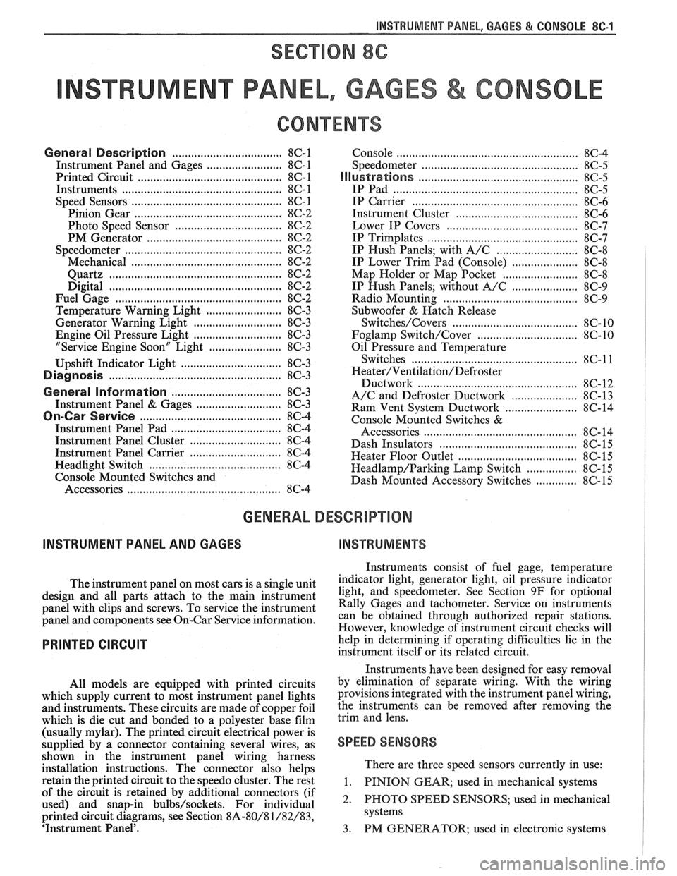
INSTRUMENT PANEL, GAGES & CONSOLE 8C-'I
SECTION 8C
NSTRUMENT PANEL, GAGES & CONSOLE
CONTENTS
General Description ................................... 8C-1
Instrument Panel and Gages ........................ 8C-1
Printed Circuit .......................................... 8C-1
Instruments ................................................... 8C- 1
Speed Sensors
............................ .. ............. 8C- 1
Pinion Gear
............................................. 8C-2
Photo Speed Sensor ................................ 8C-2
PM Generator ................... .. ...... ............... 8C-2
Speedometer ................................................ 8C-2
Mechanical ....................... .. .................... 8C-2
Quartz ........................ .. .......................... 8C-2
Digital .................... .. ...... ................. 8C-2
Fuel Gage .................................................... 8C-2
Temperature Warning Light ...................... 8C-3
Generator Warning Light ............................ 8C-3
Engine Oil Pressure Light ............................ 8C-3
"Service Engine Soon" Light ....................... 8C-3
Upshift Indicator Light .............................. 8C-3
Diagnosis .................... .. ........................... 8C-3
General Information .................................. 8C-3
Instrument Panel & Gages ...................... ..... 8C-3
On-Car Service ......................... .. ........... 8C-4
Instrument Panel Pad ................................... 8C-4
Instrument Panel Cluster ........................... 8C-4
Instrument Panel Carrier ............................. 8C-4
Headlight Switch .......................................... 8C-4
Console Mounted Switches and
Accessories
............................................... 8C-4
Console ......................................................... 8C-4
Speedometer .................................................. 8C-5
Illustra3ions ................................................. 8C-5
IP Pad ........................................................... 8C-5
IP Carrier ................................................... 8C-6
Instrument Cluster ....................................... 8C-6
Lower IP Covers ......................................... 8C-7
IP Trimplates ............................................... 8C-7
IP Hush Panels; with A/C .......................... 8C-8
..................... IP Lower Trim Pad (Console) 8C-8
Map Holder or Map Pocket ........................ 8C-8
IP Hush Panels; without A/C ..................... 8C-9
Radio Mounting ........................................... 8C-9
Subwoofer & Hatch Release
Switches/Covers ........................................ 8C- 10
Foglamp Switch/Cover ................................ 8C- 10
Oil Pressure and Temperature
Switches
..................................................... 8C-11
Heater/Ventilation/Defroster
Ductwork .................................................. 8C- 12
A/C and Defroster Ductwork ..................... 8C-13
Ram Vent System Ductwork ....................... 8C-14
Console Mounted Switches
&
Accessories ................................................. 8C- 14
Dash Insulators
............................................ 8C- 15
Heater Floor Outlet
..................................... 8C-15
................ Headlamp/Parking Lamp Switch 8C- 15
............. Dash Mounted Accessory Switches 8C- 15
GENERAL DESCRIPTION
INSTRUMENT PANEL AND GAGES
INSTRUMENTS
Instruments consist of fuel gage, temperature
The instrument panel on most cars is a sing,e unit indicator light, generator light, oil pressure indicator
design and all parts attach to the main instrument light, and speedometer. See Section 9F for optional
panel with clips and screws. To service the instrument Gages and tachometer. Service on instruments
panel and components see on-car service information, can be obtained through authorized repair stations.
However, knowledge of instrument circuit checks will
PRINTED CIRCUIT
All models are equipped with printed circuits
which supply current to most instrument panel lights
and instruments. These circuits are made of copper foil
which is die cut and bonded to a polyester base film
(usually mylar). The printed circuit electrical power is
supplied by a connector containing several wires, as
shown in the instrument panel wiring harness
installation instructions. The connector also helps
retain the printed circuit to the speedo cluster. The rest
of the circuit is retained by additional connectors (if
used) and snap-in
bulbs/sockets. For individual
printed circuit diagrams, see Section
8A-80/8 1/82/83,
'Instrument Panel'. help
in determining if operating difficulties lie in the
instrument itself or its related circuit.
Instruments have been designed for easy removal
by elimination of separate wiring. With the wiring
provisions integrated with the instrument panel wiring,
the instruments can be removed after removing the
trim and lens.
SPEED SENSORS
There are three speed sensors currently in use:
1. PINION GEAR; used in mechanical systems
2. PHOTO SPEED SENSORS; used in mechanical
systems
3. PM GENERATOR; used in electronic systems
Page 1614 of 1825
INSTRUMENT PANEL. GAGES & CONSOLE 8C-3
tank only when ignition switch is turned to "ON" or
"ACCESSORY" positions.
When ignition is turned to "OFF" or "START"
positions, the pointer may come to rest at any position.
The letters
"E" and "F" on the fuel gage are used to
point out direction of indicator travel only.
TEMPERATURE WARNING LIGHT
The engine temperature warning light is
controlled by a thermal switch which senses engine
coolant temperatures.
When the ignition switch is turned to "START"
position, a test circuit is closed and the light will come
on to indicate whether the light is functioning properly.
It is important to note that with low boiling-point
coolants (such as plain water) the temperature light
may not come on even though the coolant is boiling.
GENERATOR WARNING LIGHT
The generator warning light, located in the
instrument cluster, should come on when the ignition
switch is turned
"ON" and engine is not running. If
not, either the bulb is burned out or wiring to generator
has an open circuit.
When the generator voltage output becomes
greater than the battery voltage, the
"GEN" light
should go out. This does not, however, indicate
whether the battery is being charged or if the voltage
regulator is functioning properly.
Checks of the charging system are covered in
Section 6D, 'Engine Electrical'.
ENGINE OIL PRESSURE LIGHT
The engine oil pressure warning light is mounted
in the instrument cluster and controlled by a pressure
operated switch located on the engine block. When the ignition switch is
in the
"run" or "start9' position, the
oil pressure light should come on. If not, the bulb is
burned out, there is an open circuit between the bulb
and the oil pressure switch, or there is an open circuit
between the oil pressure switch and the choke heater.
After the engine is running, the oil pressure light
should go out when the oil pressure reaches the correct
specification. If not an oil pressure problem, a faulty oil
pressure switch or an open circuit from the choke
heater fuse to the oil pressure switch is indicated.
"SERVICE ENGINE SOON" LIGHT
All cars have a "SERVICE ENGINE SOON"
light mounted in the instrument cluster. The
"SERVICE ENGINE SOON9' light should come on
during engine starting. The light may stay on
a short
time after the engine starts.
If the light comes on while
driving, service to the emission control system may be
required. See Section
6E and Section 8A-80,
'Instrument Cluster', for complete diagnosis and
wiring diagrams of the
""P;RVICE ENGINE SOON"
light circuit.
UPSHIFT INDICATOR LIGHT
If your vehicle has a manual transmission, there
may be an
''Upshift" light on the instrument panel.
This light is illuminated to indicate optimum shift
points throughout the range from optimum fuel
economy to optimum performance. When this light is
on, shift your transmission to the next higher gear
range if conditions permit. For fuel economy,
accelerate slowly and shift when the light goes on. For
performance, accelerate as desired and shift when the
light goes on.
Safe operation of the vehicle may require shifting
differently than indicated by the "Upshift" light to
adapt to weather, road or traffic conditions.
Downshifting one or more gears may be required
to keep the engine running smoothly or to maintain
satisfactory performance.
DIAGNOSIS
Diagnostic information for all instrument panel
electrical systems is found in Section
8A-80,
'Instrument Panel'.
CAUTION: When removing or
installing any electrical units,
disconnect the negative battery cable
to prevent possible short circuits
which could lead to personal injury
and/or property damage. When
replacing a speedometer or
odometer assembly, the law requires the
odometer reading of the replacement unit to
be set to register the same mileage as the
prior odometer.
if the same mileage cannot be
set, the
law requires that the replacement
odometer be set to zero and a label be
installed on the driver's door frame to show
the previous odometer reading and the date
of replacement.
GENERAL BNFORMATlOM
INSTRUMENT PANEL AND GAGES
The instrument panel is a single unit design and
and screws. To service the instrument panel and
all parts attach to the main instrument panel with clips components see Figs. 601 through 610.
Page 1677 of 1825
96.4 MISCELLANEOUS ACCESSORIES
DASH AND CONSOLE MOUNTED ACCESSORY
SWITCHES
Installation for various dash and console
mounted accessory switches is shown in Section
8C.
GENERAL DESCRIPIIOM
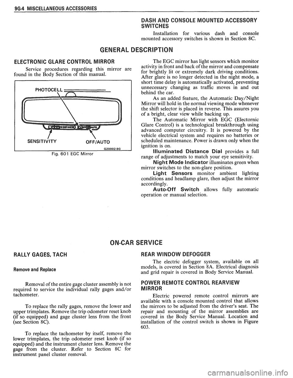
ELECTRONIC GLARE CONTROL MIRROR
Service procedures regarding this mirror are
found in the Body Section of this manual.
Fig. 601 EGC Mirror
The EGC mirror has light sensors which monitor
activity in front and back of the mirror and compensate
for brightly lit or extremely dark driving conditions.
After glare is no longer detected in the night mode, a
short time delay is automatically activated, preventing
unnecessary changing as traffic moves in and out
behind the car.
As an added feature, the Automatic
Day/Night
Mirror will hold in the normal viewing mode whenever
the shift selector is placed in reverse. This assures you
of a bright, clear view while backing up.
The Automatic Mirror with EGC (Electornic
Glare Control) is a technological breakthrough using
advanced computer circuitry. It is powered by the
vehicle electrical system and requires no batteries or
scheduled maintenance. Power is drawn only when the
ignition is on.
Illuminated Distance Dial provides a full
range of adjustments to match your eye sensitivity.
Night Mode Indicator illuminates green when
mirror switches to the non-glare position.
Light Sensors monitor ambient lighting
conditions and
headlamp glare, then adjust the mirror
accordingly.
Auto-Off Switch allows fully automatic
operation or manual selection.
ON-CAR SERVICE
RALLY GAGES, TACH REAR WINDOW DEFOGGER
Remove
and Replace
The electric defogger system, available on all
models, is covered in Section
8A. Electrical diagnosis
and grid repair is covered in Body Service Manual.
Removal of the entire gage cluster assembly is not
POWER RmOTE CONTROL REARVIEW
required to service the individual rally gages and/or MIRROR
tachometer.
Electric powered remote control mirrors are
available with a console mounted control that allows
To replace the rally gages, remove the lower and the
mirrors to be adjusted from the driver's seat. The
upper trimplates. Remove the trip odometer reset knob repair
and mounting of the mirror assemblies are
(if so equipped) and gage cluster lens from the front covered in
the Body Service Manual. Location and
(see Section
8C). installation of the control switch is shown in Figure
603.
To replace the tachometer by itself, remove the
lower trimplates, the trip odometer reset knob (if so
equipped) and the instrument cluster lens. Remove the
gage from the cluster. Refer to Section
8C for
hstrument panel cluster removal.