1988 PONTIAC FIERO radio
[x] Cancel search: radioPage 2 of 1825
1988
SER
This manual applies to the 1988 Pontiac Firebird Models.
It contains the latest product information available at the
time of publication approval. lnformation pertaining to
the operation of the vehicle is contained in the Owner's
Manual which accompanies each vehicle. The right is
reserved to make changes at any time without notice.
Any references to brand names in this manual is intended
merely as an example of the types of
lubricant% tools,
materials, etc, recommended for use in servicing 1988
Pontiac Models. In all cases, an equivalent may be used.
PONTIAC DIVISION
GENERAL
MOTORS CORPORATION
PONTIAC, MICHIGAN 48053
1987 General Motors Corp. All Rights Reserved.
No part of this publication may be reproduced, stored in any
retrieval system or transmitted in any form or by any means,
including but not limited to electronic, mechanical,
photocopying, recording or otherwise, without the prior written
permission of General Motors Corp. This includes all text,
illustrations, tables and charts.
S-881 OF 9-87 Printed in Canada
TABLE OF CONTENTS
SECTION NAME
GENERAL INFORMATION
OA. General lnformation
OB. Maintenance & Lubrication
1 SECT.
HEATING AND AIR CONDITIONING
1A. Heating and Ventilation
1 B. Air Conditioning
1D1. R-4 AIC Com~ressor Overhaul
FRAME AND BUMPERS
2B. Bumpers 2C. Chassis Sheet Metal
STEERING, SUSPENSION, WHEELS
AND TIRES
3. Diagnosis
3A. Wheel Alignment
3B5. Steering Wheels and Columns 3B6. Steering Linkage 3B7. Power Steering Gear and Pump
3C. Front Suspension
3D. Rear Suspension
3E. Tires and Wheels
FINAL DRIVE
4A. Propeller Shaft
4B. Rear Axle
4B1. Bora-Warner Axle
BRAKES 5. Brakes 5A3. Comoosite Master Cvlinder 5B1. Disc r rake Caliper ~ssembly - 300013100 Series 5B6. Disc Brake Caliper Assembly - 3548
Series
5C3. Direct Torque Drum Brake Assembly 5D2. Power Head Assembly - Tandem Diaohraam 5F. ~~ecifications and Special Tools
ENGINE 6. Engine General lnformation 6A2. 2.8L 6A3. 5.OL & 5.7L 6B. Engine Cooling
6C. En~ine Fuel
6D. ~ngine Electrical 6D1. Battery 6D2. Cranking System 6D3. Charging System 6D4. Ignition System 6D5. Engine Wiring
6E. Driveabilitv and Emissions
6E2. ~missions' 6E3. Emissions - PFI
6F. Engine Exhaust
TRANSMISSION 7A. Automatic Transmission - General
lnformation
7A1. Automatic Transmission - On-Car
Service
700R4. Automatic Transmission Hydraulic Diagnosis
700R4. Automatic Transmission Unit Repair
76. 5-Speed Manual Transmission
7C. Clutch
CHASSIS ELECTRICAL 8A. Electrical Diagnosis
8B. Lighting and Horns
8C. Instrument
Panel, Gages
& Console
8E. Windshield Wiper &Washer System
ACCESSORIES 9A. Radio Systems and Antennas 9B. Cruise Control 9G. Miscellaneous Accessories
I BODY SERVICE MANUAL END
OF
MANUAL
Page 36 of 1825
HEATING AND VENTILATION 1.4-1 3
ON-VEHICLE SERVICE
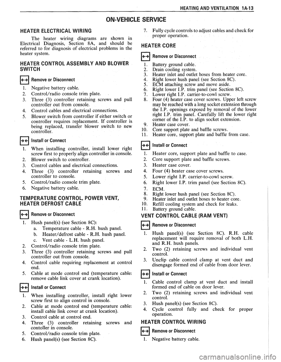
HEATER ELECTRICAL WIRING
The heater wiring diagrams are shown in
Electrical Diagnosis, Section
8A, and should be
referred to for diagnosis of electrical problems in the
heater system.
HEATER CONTROL ASSEMBLY AND BLOWER
SWITCH
Remove or Disconnect
1. Negative battery cable.
2.
Control/radio console trim plate.
3. Three
(3) controller retaining screws and pull
controller out from console.
4. Control cables and electrical connections.
5. Blower switch from controller if either switch or
controller requires replacement. If controller is
being replaced, transfer blower switch to new
controller.
Install or Connect
1. When installing controller, install lower right
screw first to properly align controller in console.
2. Blower switch to controller.
3. Control cables and electrical connections.
4. Three (3) controller retaining screws and
controller to console.
5. Control/radio console trim plate.
6. Negative battery cable.
TEMPERATURE CONTROL, POWER VENT,
HEATER DEFROST CABLE
Remove or Disconnect
1. Hush panel(s) (see Section 8C):
a. Temperature
cable - R.H. hush panel.
b.
Heateddefrost cable - R.H. hush panel.
c. Vent
cable
- L.H. hush panel.
2.
Control/radio console trim plate.
3. Three (3) controller retaining screws and pull
controller out from console.
4. Control cable requiring replacement at control
end.
5. Cable at mode control end (temperature cable:
remove cable link cover at crank location).
Install or Connect
1. When installing controller, install right lower
screw first to align control in console.
2. Cable
at mode control end (temperature cable:
install cable link cover at crank location).
3. Control cable at control end.
4. Three (3) controller retaining screws and
contoller in console.
5. Control/radio console trim plate.
6. Hush panel(s) (see Section 8C).
7. Fully cycle controls to adjust cables and check for
proper operation.
HEATER CORE
Remove or Disconnect
Battery ground cable.
Drain cooling system.
Heater inlet and outlet hoses from heater core.
Right lower hush panel (see Section
8C).
ECM attaching screw and move aside.
Right lower I.P. trim panel (see Section
8C).
Lower right I.P. carrier-to-cowl screw.
Four (4) heater case cover screws. Upper left screw
may be reached with a long socket extension through
the I.P. openings exposed by removal of the lower
right I.P. trim panel. Carefully lift the lower right
corner of the I.P. to align socket extension.
Heater case cover.
Core support plate and baffle screws.
Heater core, support plate and baffle from case.
Install or Connect
1. Heater core, support plate and baffle to case.
2. Core support
plate and baffle screws.
3. Heater case cover.
4. Four (4) heater case cover screws.
5. Lower right I.P. carrier-to-cowl screw.
6. Right lower I.P. trim panel (see Section 8C).
7. ECM.
8. Right lower hush panel (see Section
8C).
9. Heater inlet and outlet hoses to heater core.
10. Refill cooling system and check for leaks.
11. Battery ground cable.
VENT CONTROL CABLE (RAM VENT)
Remove or Disconnect 1
1. Hush panel(s) (see Section 8C). R.H. cable
replacement will require removal of both L.H.
and R.H. hush panels.
2. Two
(2) retaining screws and individual vent
control.
3. Unclip
cable control clamp at vent duct and
disengage formed end of cable from door lever.
1 Install or Connect
1. Cable control clamp at vent duct and install
formed end of cable on door lever.
2, Two (2) retaining screws and individual vent
control.
3. Hush
panel@) (see Section 8C).
4. Cycle
control fully and check for proper
operation.
HEATER CONTROL WIRING I
Remove or Disconnect
1. Negative battery cable.
Page 37 of 1825
1A-14 HEATING AND VENTILATION
2. Control/radio console trim plate and hush
panels.
3. Three (3) screws holding controller in console
and pull controller out far enough to disconnect
electrical connectors.
4. Blower motor and blower resistor electrical
connections.
5. Carefully pull cowl grommet from cowl and pull
wiring harness through cowl hole into engine
compartment.
Install or Connect
1. When reinstalling controller, install lower right
screw first to align controller.
2. Cowl grommet on cowl and wiring harness.
3. Blower motor and blower resistor electrical
connections.
4. Three (3) screws holding controller in console
and connect electrical connectors.
5. Control/radio console trim plate and hush
panels.
6. Negative battery cable.
HEATER/VENTILATION/DEFROSTER DUCTS
See section 8C for removal.
LOWER (FLOOR) HEATER OUTLET
Remove or Disconnect
1. Console (see Section 8C).
2. L.H. and R.H. hush panels. (see Section 8C).
3. Two (2) floor outlet retaining screws.
4. Floor outlet from core case.
Install or Connect
1. Floor outlet to core case.
2. Two (2) floor outlet retaining screws.
3. L.H. and R.H. hush panels.
4. Console.
BLOWER MOTOR
Remove or Disconnect
1. Negative battery cable.
2. Electrical connections at blower motor and
blower resistor.
3. Blower motor cooling tube.
4. Blower motor retaining screws and remove
motor/cage assembly from case.
5. Holding blower motor cage, remove cage
retaining screw and slide cage from motor shaft.
Install or Connect
1. Blower motor cage and retaining screw.
2. Blower
motor retaining screws and
motor/cage
assembly in case.
3. Blower motor cooling tube.
4. Electrical connections at blower motor and
blower resistor.
5. Negative battery cable.
6. Reinstall radio capacitor in proper location, if so
equipped.
Page 63 of 1825
18-28 AIR CONDITIONING
DO NOT REPLACE the accumulator assembly
when:
1. Merely a dent is found in the outer shell of the
accumulator.
2. A
vehicle is involved in a collision and no phys-
ical perforation to the accumulator is found.
OM-VEHICLE SERVICE
R-"1 CHARGING CAPACITIES
The 420ml (14 fl. oz.) disposable can of R-12
refrigerant is equivalent to .399 kg (. 88 lb.).
BLOWER MOTOR
a Remove or Disconnect
1. Disconnect negative battery cable.
2. Remove motor cooling tube.
3. Disconnect electrical connections.
4. Remove blower motor attaching screws, remove
motor and case assembly.
5. Loosen retaining nut and remove blower cage
from motor shaft.
6. Inspect blower cage for broken vanes, etc.
Replace if necessary.
Install or Connect
1. Reverse removal procedure to reinstall. Replace
seals or sealant as required.
HI-BLOWER RELAY
Relay is a plug-in type with connector mounted
on top of the evaporator case.
BLOWER RESISTOR
Remove or Disconnect
1. Disconnect negative battery cable.
2. Disconnect electrical connections.
3. Remove two (2) screws, remove resistor.
Install or Connect
1. Reverse removal procedure to reinstall.
CONTROLLER, BLOWER SWITCH OR
WCUUM VALVE
Remove or Disconnect
1. Disconnect negative battery cable.
2. Remove NC control-radio console trim plate.
3. Remove three (3) NC control retaining screws.
4. Pull A/C control out and disconnect electrical
and vacuum connections and remove tempera-
ture cable.
5. Remove A/C control and replace vacuum valve
or blower switch as required.
Install or Connect
1. Reverse removal procedure to reinstall. Install
lower right screw in controller first to align con-
troller in console.
TEMPERATURE CONTROL CABLE,
VACUUM HARNESS
Remove or Disconnect
1. Remove the following hush panel(s):
a. Vacuum Harness - R.H. and L.H. hush
panel.
b. Temperature Cable
- R.H. hush panels.
Remove
controller/radio console trim plate.
Remove three (3) controller screws and pull
controller partially out of console.
Disconnect controller
end(s) of temperature
cable
andlor vacuum harness.
Disconnect component
end(s) of temperature
cable
andlor vacuum harness.
Install or Conned
1. Reverse removal procedure to reinstall. When
installing controller, install lower right screw
first to align controller location. Replace any
retaining straps, etc. removed.
2. Perform functional check of controller.
CONTROL WlRlNG HARNESS
a Remove or Disconnect
1. Disconnect negative battery cable.
2. Remove
control/radio console trim plate and
hush panels (see Section
8C).
3. Remove three (3) screws holding control in con-
sole and pull control out far enough to discon-
nect electrical and vacuum connector. Remove
controller.
4. Remove instrument panel carrier (see Section
8C).
5. Remove heater case covers (core and mode door
sides).
6. Remove two (2) interior screws and one (1)
exterior nut holding case to cowl. Pull left side
of case back to gain access to harness at cowl.
Case will still be retained by one (I) screw
behind the evaporator core
- do not attempt
complete removal of case. -
7. Loosen cowl grommet and disconnect purple
vacuum line.
Page 470 of 1825
IGNITION SYSTEM 6D4-1
ON SYSTEM
CONTENTS
General Description ............................... 6D4-1 Service Procedures ............................. 6D4-3
Ignition System .......................................... 6D4-1
Ignition System .......................................... 6D4-3
Distributor Ignition ................................ 6D4-1
Distributor Ignition ................................ 6D4 -3
Diannosis .................................................... 6D4-3 On-Car Service ......................................... 6D4-5 -
Ignition System .......................................... (334-3 Ignition System ........................... .. .............. 6D4-5
Distributor ................................................. 6D4 -7 HE1 Distributor .................................... 6D4-3
GENERAL DESCRIPION
The engine electrical system includes the battery,
ignition (primary and secondary), starter (and related
wiring) and the generator (and related wiring).
Diagnostic charts (see Section 6D) will aid in
trouble-shooting system faults. When a fault is traced
to a particular component, refer to that components'
section of the service manual.
IGNITION SYSTEM
Distributor Ignition
The ignition circuit consists of the battery,
distributor, ignition switch, spark plugs and primary
and secondary wiring. Refer to the Battery portion of
this section for battery information.
PIE1 Distributor
The Nigh Energy Ignition (HEI) distributor with
Electronic Spark Timing (EST), used on most engines,
combines all ignition components in one unit. The
ignition coil is in the distributor cap and connects
through a resistance brush to the rotor.
The distributor has an internal magnetic pick-up
assembly which contains a permanent magnet, a pole
piece with internal teeth and a pick-up coil. When the
teeth of the timer core, rotating inside the pole piece,
line up with the teeth of the pole piece, an induced
voltage in the pick-up coil signals the electronic module
to trigger the coil primary circuit. The primary current
decreases and a high voltage is induced in the ignition
coil secondary winding. This voltage is directed
through the rotor and secondary leads to fire the spark
plugs. The capacitor in the distributor is for radio noise
suppression,
All spark timing changes in the
HE1 (EST)
distributor are done electronically by an Electronic
Control Module (ECM), which monitors information
from various engine sensors, computes the desired
spark timing and signals the distributor to change the
timing accordingly.
A back-up spark advance system
is incorporated to signal the ignition module in case of
(ECM) failure. No vacuum or mechanical advance is
used. Further (EST) information is found in sections 6E
Emissions Control, and
8A Electrical
Troubleshooting.
Ignition Timing
Timing specifications for each engine are listed in
Section
6E. When using a timing light, connect an
adapter between the No. 1 spark plug and the No. 1
spark plug wire, or use an inductive type pick-up.
Do
not pierce the plug lead.
Once the insulation of the
spark plug cable has been broken, voltage will jump to
the nearest ground, and the spark plug will not fire
properly.
Always follow the tune-up label
procedures when adjusting timing.
Some engines will incorporate a magnetic timing
probe hole for use with special electronic timing
equipment. Fig.
1A shows a typical magnetic probe
hole. Consult manufacturer's instructions for use of
this equipment.
Secondary Wiring
The spark plug wiring used with ignition systems
is a carbon impregnated cord conductor, encased in an
8MM (5/16") diameter silicone rubber jacket. The
silicone jacket withstands very high temperatures and
also provides an excellent insulator for the higher
voltage of the
HE1 system. Silicone spark plug boots
form a tight seal on the plug.
The boot should be
twisted 1/2 turn before removing. Care should
also be exercised when connecting a timing light or
other pick-up equipment. Do not force anything
between the boot and wiring, or through the silicone
jacket. Connections should be made in parallel using
an adapter. DO NOT pull on the wire to remove. Pull
on the boot, or use a tool designed for this purpose.
Spark Plugs
Resistor type, tapered seat spark plugs are used
on all engines (except aluminum heads). No gasket is
used on these tapered seat plugs. See Figs.
1B and 1C
for an explanation of coding on spark plugs.
Normal service is assumed to be a mixture of
idling, slow speed, and high speed driving. Occasional
or intermittent high-speed driving is needed for good
Page 473 of 1825
684.4 IGNITION SYSTEM
a spark plug wire from a spark plug, twist the 4. Do not wipe grease from module, or distributor
boot on the spark plug and pull
on the boot to base,
if same module is to be replaced.
remove the wire, or use a special tool designed to
remove spark plug boots.
Install or Connect
Remove or Disconnect
1. Ignition switch battery feed wire and tachometer
lead (if equipped) from distributor cap. Also
release the coil connectors from the cap. (DO
NOT use a screwdriver or tool to release the
locking tabs.)
2. Distributor cap by turning four screws
counterclockwise. Move cap out of the way.
3. Four-terminal ECM harness from distributor.
4. If necessary, remove secondary wires from cap,
release wiring harness latches and remove wiring
harness retainer. The spark plug wire numbers
are indicated on the retainer.
5. Distributor clamp screw and hold-down clamp.
6. Note position of rotor, then pull distributor up
until rotor just stops turning counterclockwise
and again note position of rotor.
To insure correct timing of the distributor,
the distributor must be INSTALLED with
the rotor correctly positioned as noted.
If the engine was accidentally cranked after the
distributor was removed, the following procedure can
be used for installing:
1. Remove No. 1 spark plug.
2. Place finger over No. 1 spark plug hole and crank
engine slowly until compression is felt.
3. Align timing mark on pulley to "0" on engine
timing indicator.
4. Turn rotor to point between No. 1 and No. 8
spark plug towers on distributor cap on V8
engines, between No. 1 and No. 6 on V6 engines,
and No.
1 and No. 4 on 4 cylinder engines.
5. Install distributor and connect ignition feed wire.
6. Install distributor cap and spark plug wires.
7. Check engine timing (see Set Ignition Timing).
Install or Connect
1. Insert distributor, positioning rotor as removed.
2. Distributor hold-down clamp and screw.
3. Wiring harness retainer and secondary wires, if
removed.
4. ECM harness connector.
5. Distributor cap.
6. Coil connectors.
7. Battery wire and tachometer lead, if equipped.
Module
It is not necessary to remove the distributor from
car.
Remove or Disconnect
1. Distributor cap and rotor.
2. Two module attaching screws, and lift module
UP. 3. Leads from module. (Observe color code on leads
as these cannot be interchanged.)
NOTICE: If a new module is to be installed, a
package of silicone grease will be included with it.
Spread the grease on the metal face of the module
and on the distributor base where the module
seats. This grease is necessary for module cooling.
1. Module.
2. Module leads (observe color code).
3. Attaching screws to module.
4. Rotor.
5. Cap.
Pick-Up Coil
1. Remove distributor from car and follow
instructions in Unit Repair, as applicable.
Rotor
Fig. 1
1. Remove distributor cap.
2. The rotor is retained by two screws and is
provided with a slot which fits over a square lug,
,
so that the rotor can be installed in only one
position.
Integral Ignition Coil
Fig. I
Remove or Disconnect
1. Distributor cap.
2. Three coil cover attaching screws, and lift off
cover.
3. Coil attaching screws and lift ignition coil and
leads from cap.
Install or Connect I
1. Coil and attaching screws.
2. Coil leads.
3. Coil cover and attaching screws.
Capacitor
Fig. 1
The capacitor is part of the coil wire harness
assembly. Since the capacitor is used only for radio
noise suppression, it will seldom need replacement.
Remove or Disconnect I
1. Distributor cap and rotor.
2. Capacitor attaching screw and unplug connector
from module. It may help to loosen the module.
Install or Connect I
1. Plug into module.
2. Capacitor and hold-down screw (be sure ground
lead is under screw).
Page 474 of 1825
IGNITION SYSTEM 6014.5
3. Rotor and cap. 4. Turn off the engine and remove the timing light.
Reconnect the number one spark plug wire, if
Set Ignition Timing removed.
Spark Plug Wires 1. Refer to the tune-up label located in the engine
compartment. Follow all instructions on the Use
care when removing spark plug wire boots
label. from
spark plugs. Twist the boot
1/2 turn before
removing and pull on the
boot only to remove the
With ignition off, connect the pick-up lead of
timing light to the number one spark plug. Use
a jumper lead between the wire and plug, or an
inductive type pick-up.
DO NOT pierce the wire,
or attempt to insert a wire between the boot and
the wire. Connect the timing light power leads
according to manufacturer's instructions.
Start the engine and aim the timing light at the
timing mark. The line on the balancer or pulley
will line up at the timing mark. If a change is
necessary, loosen the distributor hold-down
clamp bolt at the base of the distributor. While
observing the mark with the timing light, slighty
rotate the distributor until the line indicates the
correct timing. Tighten the hold-down bolt and
re-check the timing. wire.
When replacing plug wires, route the wires
correctly and through the proper retainers. Failure to
route the wires properly can lead to radio ignition noise
and crossfiring of the plugs, or shorting of the leads to
ground.
Special care should be exercised when reinstalling
spark plug boots, to assure that the metal terminal
within the boot is fully seated on the spark plug
terminal and that the boot has not moved on the wire.
If boot to wire movement has occurred, the boot will
give a false visual impression of being fully seated.
A
good check to assure that boots have been properly
assembled is to push sideways on the installed boots.
If they have been correctly installed, a stiff boot, with
only slight looseness, will be noted. If the terminal has
not been properly seated on the spark plug, only the
resistance of the rubber boot will be felt when pushing
sideways.
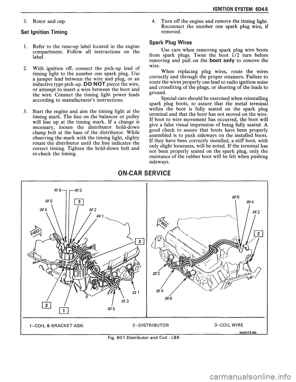
ON-CAR SERVICE
I I -COI L & BRACKET ASM. 2-DISTRIBUTOR 3-COIL WIRE I
Fig. 601 Distributor and Coil - LB8
Page 549 of 1825
6EZ-B-2 5.OL (VIN E) DRIVEABILITY AND EMISSIONS
Problem may or may not turn "ON" the "Service Engine Soon" light, or store a code.
DO NOT use the trouble code charts in Section
"A" for intermittent problems. The fault must be
present to locate the problem. If a fault is
intermittent, use of trouble code charts may result
in replacement of good parts.
@ Most intermittent problems are caused by faulty
electrical connections or wiring. Perform
careful check of suspect circuits for:
- Poor mating of the connector halves, or
terminals, not fully seated in the connector
body (backed out).
I - Improperly formed or damaged terminals.
All connector terminals in problem circuit
should be carefully reformed to increase
contact tension.
- Poor terminal to wire connection. This
requires removing the terminal from the
connector body to check as outlined in the
Introduction to Section
"6E".
@ If a visual (physical) check does not find the
cause of the problem, the car can be driven with
a voltmeter connected to a suspected circuit or a
"Scan" tool may be used. An abnormal voltage
reading, when the problem occurs, indicates the
problem may be in that circuit. If the wiring
and connectors check OK, and a trouble code was
stored for a circuit having a sensor, except
for Codes 44 and 45, substitute a known good
sensor and recheck.
@ Loss of trouble code memory. To check,
disconnect TPS and idle engine until "Service
Engine Soon" light comes
"ON". Code 22 should
be stored, and kept in memory, when ignition is
turned "OFF" for at least 10 seconds. If not, the
ECM
is faulty.
@ An intermittent "SES" light, and no trouble
codes, may be caused by:
- Electrical system interference caused by a
defective relay, ECM driven solenoid, or switch.
They can cause a sharp electrical surge.
Normally, the problem will occur when the
faulty component is operated.
- Improper installation of electrical options, such
as lights, 2-way radios, etc.
- EST wires should be routed away from spark
plug wires, ignition system components, and
generator. Wire for CKT 453 from ECM to
ignition system should be a good ground.
- Ignition secondary shorted to ground.
- CKTs 419 ("SES" light) or 451 (Diagnostic Test)
intermittently shorted to ground.
- ECM power grounds.
HARD START
Definition: Engine cranks OK, but does not start for a long
time. Does eventually run, or may start but immediately dies.
, <
@ CHECK: 4. Connect a radiator test pump to the line and
- For water contaminated fuel. apply 103 kPa (15 psi) pressure. If the
- Fuel system pressure CHART A-7. pressure will hold for 60 seconds, the check
- TPS for sticking or binding should read less than
valve is OK.
1.25 volts on a "Scan" tool. @ Check ignition system for:
- No crank signal; see CHART C-1B. - Proper output with ST-125.
- EGR operation; CHART C-7. - Worn shaft.
- Fuel System - CHART A-7. - Rare and shorted wires.
- For a faulty in-tank fuel pump check valve, - Pickup coil resistance and connections.
which would allow the fuel in the lines to drain
- Loose ignition coil connections.
back to the tank after the engine is stopped. To
- Moisture in distributor cap.
check for this condition:
- Spark plugs, wet plugs, cracks, wear,
1. Ignition "OFF".
improper gap, burned electrodes, or heavy
2. Disconnect fuel line at the filter
deposits.
3. Remove the tank filler cap. @ If engine starts but then, immediately stalls,
open distributor bypass line. If engine then
starts, and runs OK, replace distributor pickup
coil.
@ Check CKT 423 (EST) for short to ground.