Page 1496 of 1825
Page 1499 of 1825

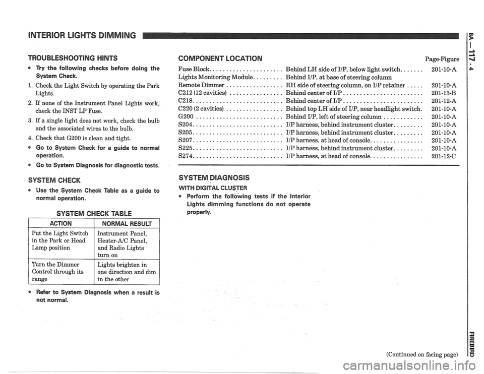
INTERIOR LIGHTS DIMMING
TROUBLESHOOTlNG HINTS COMPONENT LOGATlON Page-Figure
a Try the following checks before doing the Fuse Block. ..................... Behind LN side of IIP, below light switch. ...... 201-10-A
System Check. Lights Monitoring Module. ........ Behind IIP, at base of steering column
................. ..... 1. Check the Light Switch by operating the Park RN
side of steering column, on IIP retainer 201-10-A
................ ........................ Lights. 6212 (12-cavities) Behind center of IIP 201-13-B -
.......................... ........................ 2. If none of the Instrument Panel Lights work, C218. Behind center of IIP 201-12-A
................. check the INST LP Fuse. C220 (2 cavities) Behind top LH side of IIP, near headlight switch. 201-10-A
............ 6200 .......................... Behind IIP, left of steering column 201-10-A
3. If a single light does not work, cheek the bulb ........ S204. .......................... IIP harness, behind instrument cluster. 201-10-A and the associated wires to the bulb. ........ S205. .......................... IIP harness, behind instrument cluster. 201-10-A
4. Check that 6200 is clean and tight. ............... S207. .......................... IIP harness, at head of console. 201-10-A
@ Go to System Check for a guide to normal S225. .......................... IIP harness, behind instrument cluster. ........ 201-10-A
operation. $274. .......................... IIP harness, at head of console. ............... 201-12-C
s Go to System Diagnosis for diagnostic tests.
SYSTEM CHECK SYSTEM DIAGNOSIS
Use the System Check Table as a guide to WITH DIGITAL CLUSTER
normal operation. r Perform
the follbking tests if the Interior
Lights dimming functions do not operate
properly.
SYSTEM CHECK TABLE
ACTION
Put the Light Switch
in the Park or
Head
Lamp position
Refer to System Diagnosis when a result is
not normal.
NORMAL RESULT
Instrument Panel,
Heater-AIC Panel,
and Radio Lights
turn on
Turn the Dimmer
Control through its
range
(Continued on facing page)
Lights brighten
in
one direction and dim
in the other
Page 1520 of 1825

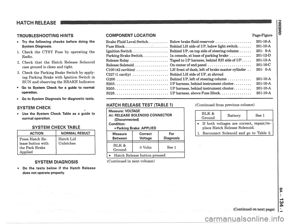
HATCH RELEASE P
E
TROUBLESHOOTING H lNTS
0 Try the following checks before doing the
System Diagnosis.
1. Check the CTSY Fuse by operating the
Radio.
2. Check that the Hatch Release Solenoid
case ground is clean and tight.
3. Check the Parking Brake Switch by apply-
ing Parking Brake with Ignition Switch in
RUN and observing the BRAKE Indicator.
@ Go to System Check for a guide to normal
operation.
Go to System Diagnosis for diagnostic tests.
SYSTEM CHECK -
o Use the System Check fable as a guide to
normal operation.
SYSTEM CHECK TABLE
lease button with
SYSTEM DIAGNOSIS
e Do the tests below if the Hatch Release
does not operate properly.
COMPONENT LOCATION Page-Figure
Brake Fluid Level Switch. ......... Below brake fluid reservoir ..................
Fuse Block. ..................... Behind LN side of IIP, below light switch. ......
Ignition Switch. ................. Behind IIP, on top side of steering column ......
Parking Brake Switch. ............ In console, at base of parking brake ...........
Release Relay ................... Taped to IIP harness, behind RN side of IIP. ....
Release Solenoid ................. On center of end panel ......................
el00 (42 cavities) ................ LN front of dash, left of brake master cylinder ..
C227 (1 cavity) .................. Behind LN side of IIP, at shroud
6200
.......................... Behind IIP, left of steering c
S203. .......................... IIP harness, behind instrunnent cluster. ........
.......................... ........ S205. IIP harness, behind instrument cluster.
S228. .......................... IIP harness, above Fuse Block. ...............
WATGH RELEASE TEST (TABLE 1)
At: RELEASE SOLENOID CONNECTOR
(Disconnected)
I 0 Parkina Brake: APPLIED I
I Measure I Correct I For
(Continued from previous column)
BLK & 1 o volts I See I 1 Ground
I r Hatch Release button pressed I --
(Continued in next column)
(Continued on next page)
Page 1541 of 1825
RADIO 00 D
WITH UK3 AND SUBWOOFER AMPLlFlER I
Page 1543 of 1825
RADIO la, P
WITH UK3 AND SUBWOOFER AMPLIFIER I
Page 1544 of 1825
-, RADIO
WITHOUT SUBWOOFER AMPLlFlER AND UK3
POWER ANTENNA
Page 1545 of 1825
RADIO
WITH SUBWOOFEW AMPLIFIER AND WITHOUT UK3
Page 1546 of 1825
RADIO
WITH SUBWOOFER AMPLIFIER AND WITHOUT UK3
INTERIOR LIGHTS
- -