1988 PONTIAC FIERO radio
[x] Cancel search: radioPage 1615 of 1825
8C.4 INSTRUMENT PANEL, GAGES & CONSOLE
ON-CAR SERVlCE
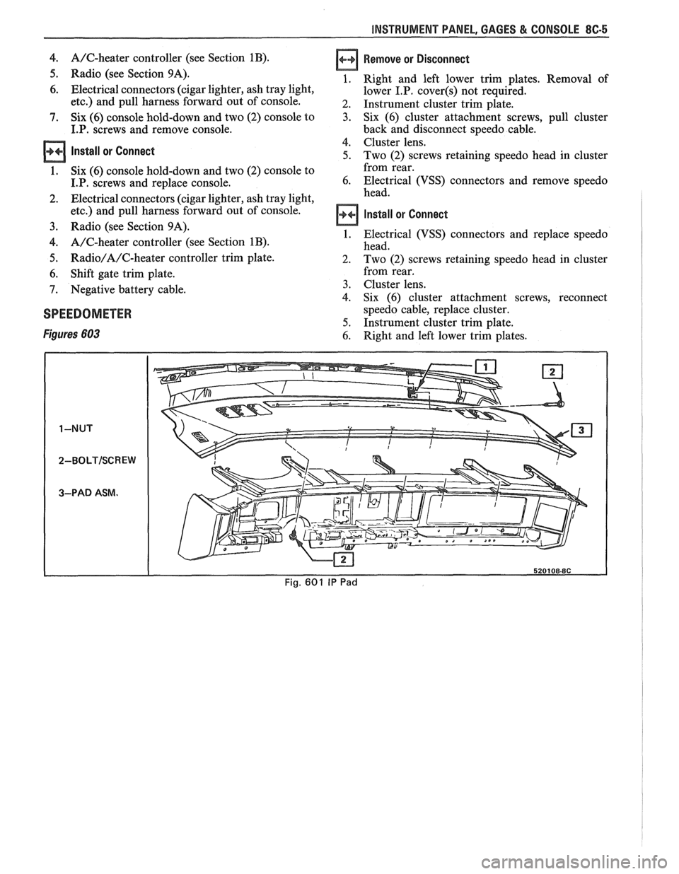
lNSTRUMEMT PANEL PAD
Figure 601
Remove or Disconnect
1. Four (4) screws in defroster ducts.
2. Screws
under lip of
I.P, pad.
3. I.P. pad from carrier.
lnstall or Connect
1. I.P. to carrier.
2. Screws
under lip of I.P. pad.
3. Four (4) screws in defroster ducts.
INSTRUMENT PANEL CLUSTER
Figure 683
Remove or Disconnect
1. Right and left lower trim plates. Removal of
lower I.P. covers not required.
2. Instrument cluster trim plate.
3. Six (6) cluster attachment screws, pull cluster
back and disconnect speedo cable and electrical
connections.
4. Trip odometer, reset knob (if so equipped) and
remove cluster lens.
5. Individual gages and/or speedo head are now
accessible for service or replacement. If service is
intended for only gages or tachometer, skip Step
3.
Install or Connect
1. Trip odometer, reset knob (if so equipped) and
remove cluster lens.
2. Six
(6) cluster attachment screws, pull cluster
back and disconnect speedo cable and electrical
connections.
3. Instrument cluster trim plate.
4. Right and left lower trim plates. Removal of
lower I.P. covers not required.
INSTRUMENT PANEL CARRIER
Figure 602
Remove or Disconnect
Negative battery cable.
Console. Instrument panel pad and lower hush panels.
Right and left lower I.P. covers and trim plates.
Instrument panel cluster and headlight switch.
Lower steering column.
Five (5) upper and six (6) lower I.P. carrier to
cowl screws.
Instrument panel electrical harness at cowl
(bulkhead) connector, and under dash.
I.P. carrier from car.
10. I.P. mounted components (A/C, defroster ducts,
wiring harness, etc.) are now accessible for service
or replacement.
11. Any seals or sealant damaged during
disassembly.
Install or Connect
I.P. carrier to car.
Instrument panel electrical harness at cowl
(bulkhead) connector, and under dash.
Five (5) upper and six (6) lower I.P. carrier to
cowl screws.
Steering column.
Instrument panel cluster and headlight switch.
Right and left lower I.P. covers and trim plates.
Instrument panel pad and lower hush panels.
Console.
Negative battery cable.
HEADLIGHT SWITCH
Figure 620
Remove or Disconnect
1. Right and left lower trim plates. Removal of
lower I.P.
cover(s) not required.
2. I.P. cluster trim plate.
3. Two (2) switch assembly retaining screws.
4. Depress side tangs and pull switch assembly from
I.P.
5. Individual switches of assembly are now
accessible for service or replacement.
Install or Connect
1. Depress side tangs and replace switch assembly
to I.P.
2. Two
(2) switch assembly retaining screws.
3. I.P. cluster trim plate.
4. Right and
left lower trim plates. Removal of
lower I.P.
cover(s) not required.
DASH MOUNTED ACCESSORY SWITCHES
Figure 62 1
Installation for various dash mounted accessory
switches is shown in Fig.
62 1.
CONSOLE MOUNTED SWITCHES AND
ACCESSORIES
Figure 6 17
Installation of various console mounted switches,
lights and accessories is shown in Figure 617.
CONSOLE
Remove or Disconnect
1. Negative battery cable.
2. Shift gate trim plate. Requires removal
of shift
handle and seven (7) screws.
3. Radio/A/C-heater controller trim plate.
Page 1616 of 1825
INSTRUMENT PANEL, GAGES & CONSOLE 8C-5
4. A/C-heater controller (see Section 1B).
5. Radio (see Section 9A).
6. Electrical connectors (cigar lighter, ash tray light,
etc.) and pull harness forward out of console.
7. Six (6) console hold-down and two (2) console to
I.P. screws and remove console.
Install or Connect
1. Six (6) console hold-down and two (2) console to
I.P. screws and replace console.
2. Electrical connectors (cigar lighter, ash tray light,
etc.) and pull harness forward out of console.
3. Radio (see Section 9A).
4. A/C-heater controller (see Section 1B).
5. Radio/A/C-heater controller trim plate.
6. Shift gate trim plate.
7. Negative battery cable.
SPEEDOMETER
Figures 603
Remove or Disconnect
Right and left lower trim plates. Removal of
lower
I.P. cover(s) not required.
Instrument cluster trim plate.
Six (6) cluster attachment screws, pull cluster
back and disconnect speedo cable.
Cluster lens.
Two (2) screws retaining speedo head in cluster
from rear.
Electrical (VSS) connectors and remove speedo
head.
Install or Connect
Electrical (VSS) connectors and replace speedo
head.
Two (2) screws retaining speedo head in cluster
from rear.
Cluster lens.
Six (6) cluster attachment screws, reconnect
speedo cable, replace cluster.
Instrument cluster trim plate.
Right and left lower trim plates.
Page 1620 of 1825
INSTRUMENT PANEL, GAGES & CONSOLE 8C-9
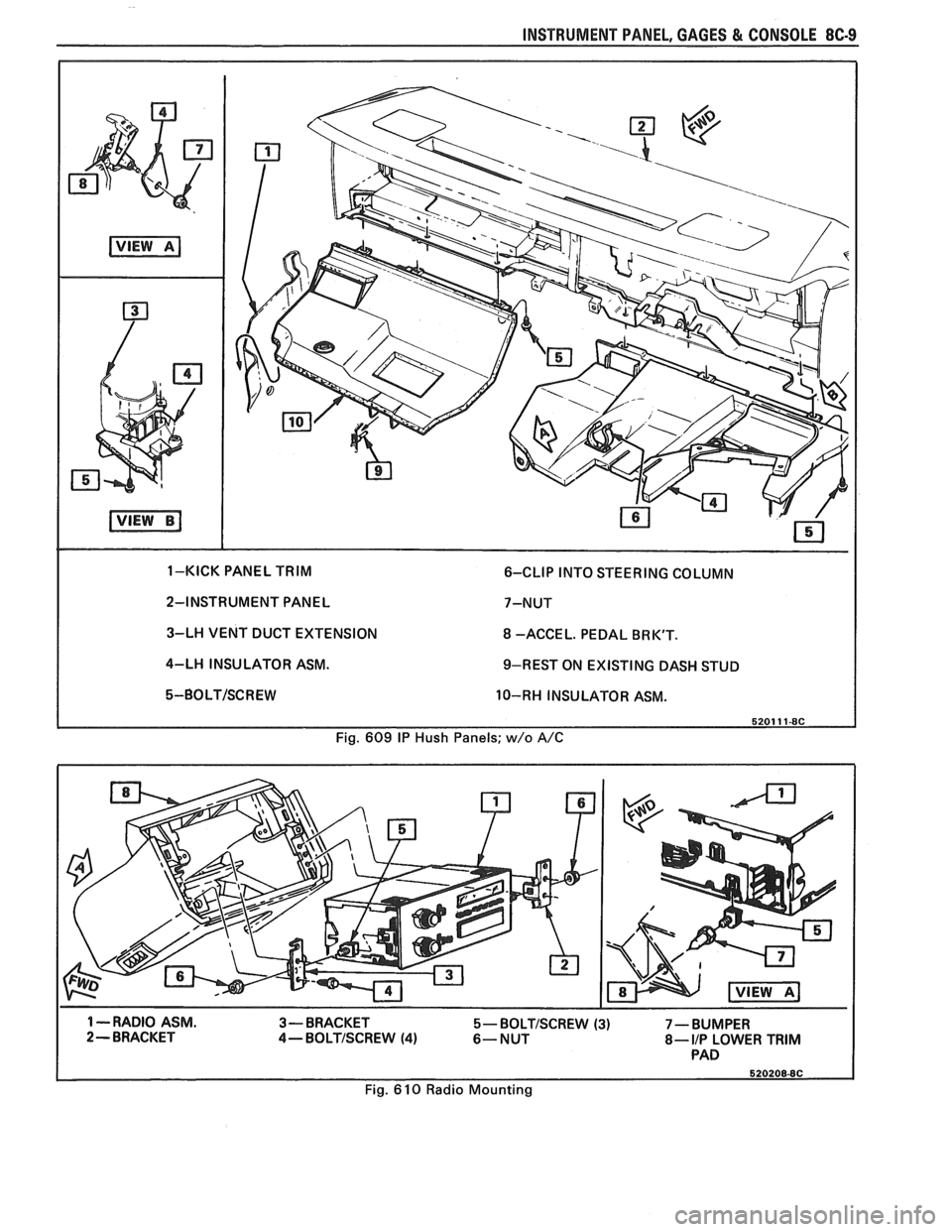
2-INSTRUMENT PANEL 7-NUT
3-LH VENT DUCT EXTENSION
8 -ACCE L. PEDAL BR K'T.
4-LH INSULATOR ASM.
9-REST ON EXISTING DASH STUD
5-BOLT/SCREW 10-RH INSULATOR ASM.
Fig. 609
IP Hush Panels; w/o A/C
1 --RADIO ASM.
3-BRACKET 5- BOLTISCREW (3) 7 - BUMPER 2- BRACKET 4-BOLTISCREW (4) 6-NUT 8- I/P LOWER TRIM PAD
Fig. 610 Radio Mounting
Page 1650 of 1825
RADIO SYSTEMS AND ANTENNAS 9A-1
SECTION 9A
0 SYSTEMS AND ANTENNAS
CONTENTS
............................................. General Description .................................... 9A-1 Radio Operation 9A-4
Radio
............................................................ 9A-1 ETR AM/FM Stereo (UM-7) ....................... 9A-4
Antennas
........................................................ 9A- 1 ETR Stereo Cassette (UM-6) ......................... 9A-5
Fixed Antenna
.......................................... 9A- 1 ETR Stereo/Cassette/Eaualizer
Diagnosis ........................................................
Radio ....................... .. ................................
Static and Noise .................................... .....
........................................ Popping Noise
Preliminary Diagnostics
.............................
Antenna ................................. .. ................
Tape Player .................. .... .......................
Service Procedures ....................................
Radio and Speakers ........................... .............
Radio Noise Suppression Equipment ............
Stereo Cassette Tape Player ..........................
Tape & Tape Player Care ........................
(UX-1) ..................................................... 9A-6
Advanced ETR
Stereo/Cassette/Equalizer Touch
Control
.................................... ... .............. 9A-7
On-Car Service .............................................. 9A-9
Radio Receiver
............................................ 9A-9
Radio Steering Wheel Controls
..................... 9A-9
Audio Amplifier
........................................... 9A-9
Radio Suppression
..................................... 9A-9
Front Speaker
................................................. 9A-9
............... Rear Speaker; Sub Woofer Speaker
9A-9
Antenna
..................... .. ............................. 9A- 10
GENERAL DESCRIPUION
RADIO ANTENNAS
For radios and radio use see the "Radio Fixed Antenna
Operation" section. ETR means 'Electronically Tuned The
fixed antenna on the right front fender
Receiver'. cannot be adjusted up or down. It may provide
improved reception in rural areas.
- The fixed antenna is designed to withstand most
car washes without damage. If the antenna becomes
slightly bent, you can straighten it by hand. The
antenna can be replaced if severely bent (by vandalism,
etc.). Antennas must be kept clean for good
performance.
RADIO
Because radio problems are normally repaired at
authorized warranty repair stations, the tendency is to
remove the set when a problem is reported, without any
preliminary diagnosis. This results in a large number
of radios being "No Trouble Found" units when
received by the warranty repair stations. Often the
trouble can be corrected without radio removal. wire.
If equipped with
A/C, the blower motor has a
built-in capacitor. Extra electrical equipment added to
the static if not properly grounded or wiring was
improperly routed.
Weak
FM station reception will be affected by
nearby buildings, car speed and direction. These
"flutter" and "fading" conditions are characteristic of
weak FM signals.
ETR radios require clock and button reset if the
battery is disconnected.
Popping Noise
Static and Noise Operating devices such as turn signals, pushing in
cigarette lighter, operating stop lights, etc., may cause
Ground strap connections must be clean and
a popping noise on distant (weak) AM signals.
tight, spark plug cables must be TVRS type and in
good condition and resistance-type spark plugs used.
Preliminary Diagnostics
Capacitors are used in the generator, heating/air
conditioning system, and fuse panel to reduce noise
The inconvenience of driving without a radio
entering the radio through the feed wires. If the car has
while the set is being serviced can often be avoided if
a heater only, the capacitor is in the blower motor feed
the following quick checks are used to eliminate
Page 1651 of 1825
9A-2 RADlO SYSTEMS - AND ANTENNAS
external radio system problems before removing the
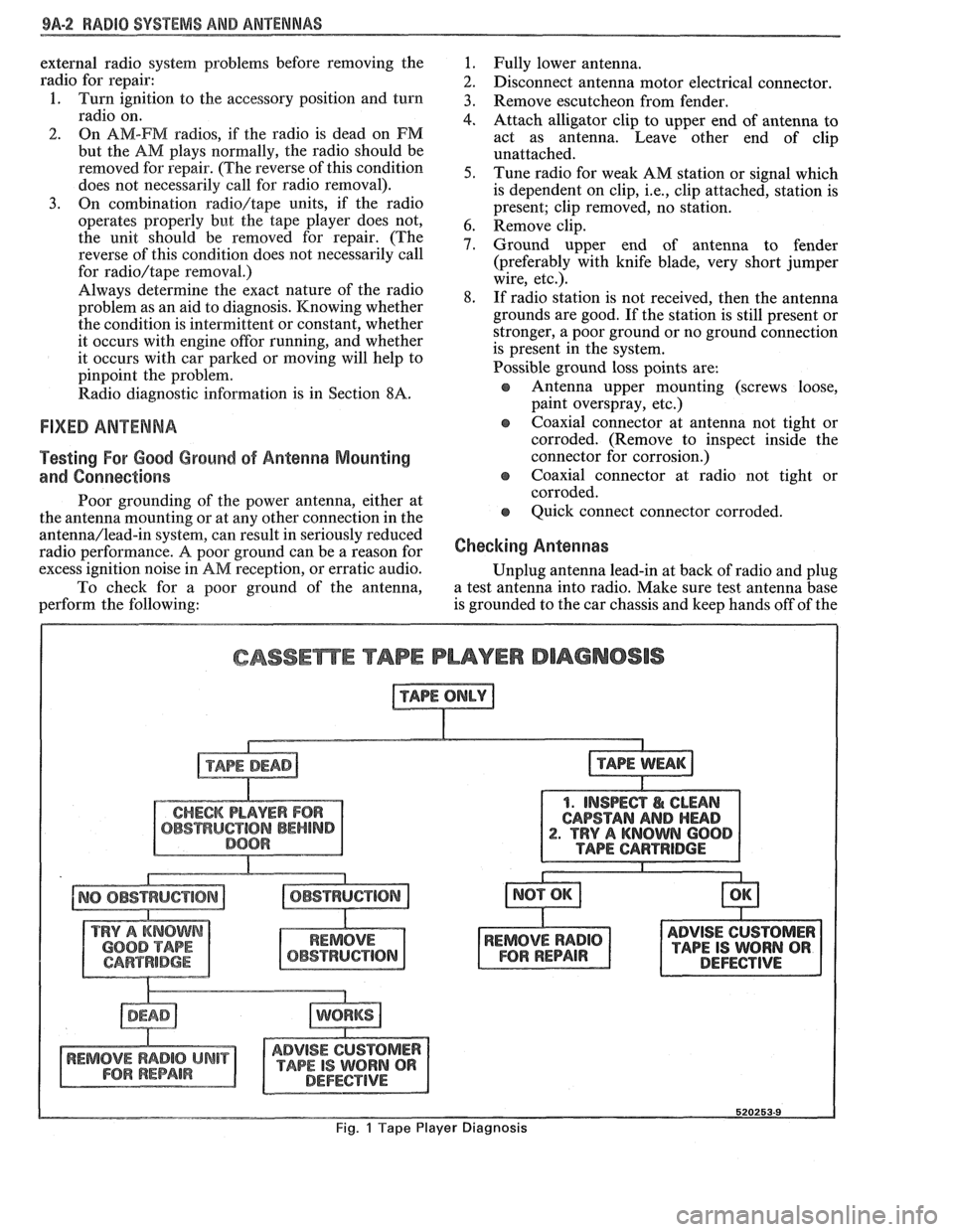
radio for repair:
1. Turn ignition to the accessory position and turn
radio on.
2. On AM-FM radios, if the radio is dead on FM
but the AM plays normally, the radio should be
removed for repair. (The reverse of this condition
does not necessarily call for radio removal).
3. On combination radio/tape units, if the radio
operates properly but the tape player does not,
the unit should be removed for repair. (The
reverse of this condition does not necessarily call
for
radio/tape removal.)
Always determine the exact nature of the radio
problem as an aid to diagnosis. Knowing whether
the condition is intermittent or constant, whether
it occurs with engine
offor running, and whether
it occurs with car parked or moving will help to
pinpoint the problem.
Radio diagnostic information is in Section
8A.
FIXED ANTENNA
Testing For Good Ground of Antenna Mounting
and Connections
Poor grounding of the power antenna, either at
the antenna mounting or at any other connection in the
antenna/lead-in system, can result in seriously reduced
radio performance.
A poor ground can be a reason for
excess ignition noise in
AM reception, or erratic audio.
To check for a poor ground of the antenna,
perform the following:
1. Fully lower antenna.
2. Disconnect antenna motor electrical connector.
3. Remove escutcheon from fender.
4. Attach alligator clip to upper end of antenna to
act as antenna. Leave other end of clip
unattached.
5. Tune radio for weak AM station or signal which
is dependent on clip,
i.e., clip attached, station is
present; clip removed, no station.
6. Remove clip.
7. Ground upper end of antenna to fender
(preferably with knife blade, very short jumper
wire, etc.).
8. If radio station is not received, then the antenna
grounds are good. If the station is still present or
stronger, a poor ground or no ground connection
is present in the system.
Possible ground loss points are:
s Antenna upper mounting (screws loose,
paint overspray, etc.)
e coaxial connector at antenna not tight or
corroded. (Remove to inspect inside the
connector for corrosion.)
e Coaxial connector at radio not tight or
corroded.
e Quick connect connector corroded.
Checking Antennas
Unplug antenna lead-in at back of radio and plug
a test antenna into radio. Make sure test antenna base
is grounded to the car chassis and keep hands off of the
CASSEmE TAPE PLAYER DIAGNOSIS
1. INSPECT I& CLEAN
CAPSTAN
AND HEAD . TRY A KNOWN 600
ADVISE CUSTOMER
TAPE IS WORN QR DEFECTIVE
Fig. 1 Tape Player Diagnosis
Page 1652 of 1825
RADIO SYSTEMS AND ANTENNAS 9A-3
antenna. Check radio reception in an area away from
reception. If reception is OK, problem exists with
electrical interferences. These include tall buildings,
antenna and/or its lead-in cable. If reception is still
metal structures, power lines, fluorescent lighting, and
poor, refer to Section
8A.
power tools. Tune to high and low ends of the dial on
both AM and FM checking weak and strong station
reception. If reception is OK, problem exists with
antenna and/or its lead-in cable. If reception is still
poor, refer to Section
8A.
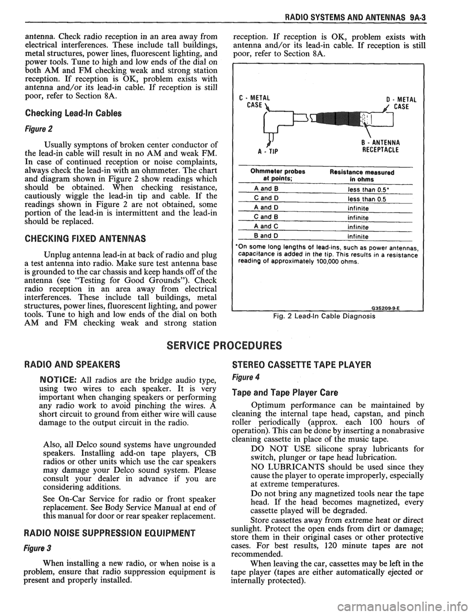
Checking Lead-In Cables
Figure 2
Usually symptons of broken center conductor of
the lead-in cable will result in no AM and weak FM.
In case of continued reception or noise complaints,
always check the lead-in with an ohmmeter. The chart
and diagram shown in Figure
2 show readings which
should be obtained. When checking resistance,
cautiously wiggle the lead-in tip and cable. If the
readings shown in Figure
2 are not obtained, some
portion of the lead-in is intermittent and the lead-in
should be replaced.
CHECKING FIXED ANTENNAS
Unplug antenna lead-in at back of radio and plug
a test antenna into radio. Make sure test antenna base
is grounded to the car chassis and keep hands off of the
antenna (see "Testing for Good Grounds"). Check
radio reception in an area away from electrical
interferences. These include tall buildings, metal
structures, power lines, fluorescent lighting, and power
tools. Tune to high and low ends of the dial on both
AM and FM checking weak and strong station
less than 0.5'
less than 0.5
'On some long lengths
of lead-ins, such as power antennas,
capacitance is added in the tip. This results in a resistance
reading of approximately 100,000 ohms.
Fig. 2 Lead-In Cable Diagnosis
SERVICE PROCEDURES
RADIO AND SPEAKERS
STEREO CASSETTE TAPE PLAYER
NOTICE: All radios are the bridge audio type,
using two wires to each speaker. It is very
important when changing speakers or performing
any radio work to avoid pinching the wires. A
short circuit to ground from either wire will cause
damage to the output circuit in the radio.
Also, all Delco sound systems have ungrounded
speakers. Installing add-on tape players, CB
radios or other units which use the car speakers
may damage your Delco sound system. Please
consult your dealer in advance if you are
considering additions.
See On-Car Service for radio or front speaker
replacement. See Body Service Manual at end of
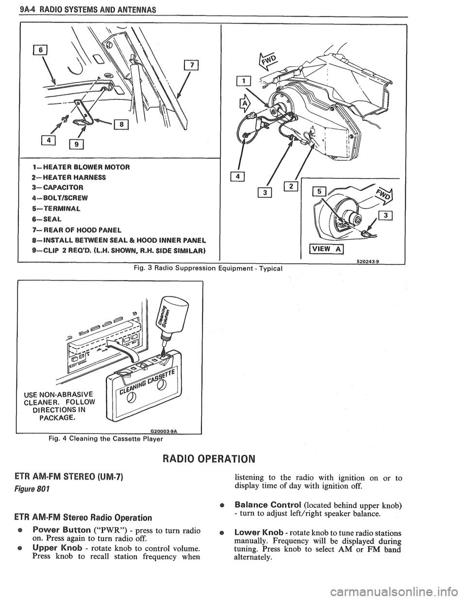
this manual for door or rear speaker replacement. Figure 4
Tape and Tape Player Care
Optimum performance can be maintained by
cleaning the internal tape head, capstan, and pinch
roller periodically (approx. each 100 hours of
operation). This can be done by inserting a nonabrasive
cleaning cassette in place of the music tape.
DO NOT USE silicone spray lubricants for
switch, plunger or tape head lubrication.
NO LUBRICANTS should be used since they
cause the player to operate improperly, especially
at extreme temperatures.
Do not bring any magnetized tools near the tape
head. If the head becomes magnetized, every
cassette played will be degraded.
Store cassettes away from extreme heat or direct
RADIO NOISE SUPPRESSION EQUIPMENT sunlight. Protect the open ends from dirt or damage;
store them in their original cases or other protective
Figure 3 cases. For best results, 120 minute tapes are not
recommended.
When installing a new radio, or when noise is a
When leaving the car, cassettes may be left in the
problem, ensure that radio suppression equipment is
tape player (tapes are either automatically ejected or
present and properly installed.
internally protected).
Page 1653 of 1825
98-4 RADIO SYSTEMS AND ANTENNAS
USE NON-ABRASIVE
CLEANER. FOLLOW
DIRECTIONS
IN PACKAGE.
Fig. 4 Cleaning the Cassette Player
RADIO OPERATION
ETR AM-FM STEREO (UM-7)
Figure (30 1
ETW AM-FM Stereo Radio Operation
listening to the radio with ignition on or to
display time of day with ignition off.
e Balance Control (located behind upper knob)
- turn to adjust left/right speaker balance.
@ Power Button ("PWR) - Press to turn radio e Lower Knob - rotate knob to tune radio stations
on. Press again to turn radio off.
manually. Frequency will be displayed during
Upper Knob - rotate knob to control volume. tuning. Press knob to select AM or FM band
Press knob to recall station frequency when
alternately.
Page 1654 of 1825
RADIO SYSEEMS AWlD ANTENNAS 9A-5
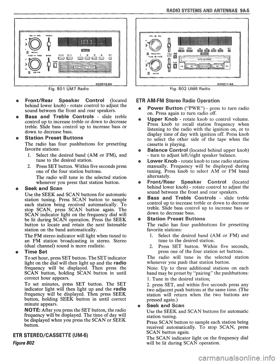
Fig. 801 UM7 Radio
Front/Rear Speaker Control (located
behind lower knob)
- rotate control to adjust the
sound between the front and rear speakers.
e Bass and Treble Controls - slide treble
control up to increase treble or down to decrease
treble. Slide bass control up to increase bass or
down to decrease bass.
e Station Preset Buttons
The radio has four pushbuttons for presetting
favorite stations:
1. Select the desired band (AM or FM), and
tune to the desired station.
2. Press SET button. Within five seconds press
one of the four station buttons.
The radio will tune in the selected station
whenever you press that station button.
e Seek and Scan
Use the SEEK and SCAN buttons for automatic
station tuning. Press SCAN button to sample
each station being received automatically. To
stop SCAN, press SCAN button again. The
SCAN indicator light on the frequency dial will
be lit during SCAN operation. Press the SEEK
button to locate and retain the next listenable
station on the band automatically.
The FM stereo indicator will light when tuned to
an FM station broadcasting in stereo. Stereo
(dual channel) sound is more realistic.
a Time Set
To set hour, press SET button. The SET indicator
light on the dial will then light up and the
radio
frequency will be displayed. Then press the
SCAN button, holding SCAN button in until
correct hour appears.
To set minutes, press SET button. The SET
indicator light will then light up and the
radio
frequency will be displayed. Then press SEEK
button, holding SEEK button in until correct
minute appears.
NOTE: After you press the SET button, the radio
frequency will be displayed. The time of day will
be displayed when you press the SCAN or SEEK
button.
ETR STEREO/GASSETTE (UM-6)
Figure 802
Fig. 802 UM6 Radio
Ef R AM-FM Stereo Radio Operation
Power Button ("PWR") - press to turn radio
on. Press again to turn radio off.
Upper Knob - rotate knob to control volume.
Press knob to recall station frequency when
listening to the radio with the ignition on, or to
display time of day with ignition off. Press knob
to select the other side of the tape when the
cassette is playing.
Balance Control (located behind upper knob)
- turn to adjust left/right speaker balance.
Lower Knob - rotate knob to tune radio stations
manually. Frequency will be displayed during
tuning. Press knob to select
AM or FM band
alternately.
Front/Rearr Speaker Control (located
behind lower knob)
- rotate control to adjust the
sound between the front and rear speakers.
Bass and Treble Controls - slide treble
control up to increase treble or down to decrease
treble. Slide bass control
up to increase bass or
down to decrease bass.
Station Preset Buttons
The radio has four pushbuttons for presetting
favorite stations:
1. Select the desired band (AM or FM) and
tune to the desired station.
2. Press SET button. Within five seconds,
press one of the four station set buttons.
The radio will tune in the selected station
whenever you push that station button.
Note: Up to three additional stations on each
band may be preset by "pairing" the pushbuttons:
1. Tune in the desired station;
2. press SET, and within five seconds press any
two adjacent push buttons at the same time. (The
station will return when the two buttons are
pressed again.)
Seek and Sean
Use the SEEK and SCAN buttons for automatic
station tuning.
Press SCAN button to
sample each station being
received automatically. To stop SCAN, press
SCAN button again.
The SCAN indicator light on the frequency dial
will be lit during SCAN operation.