1988 PONTIAC FIERO timing belt
[x] Cancel search: timing beltPage 349 of 1825
6-4 ENGINE GENERAL INFORMATION
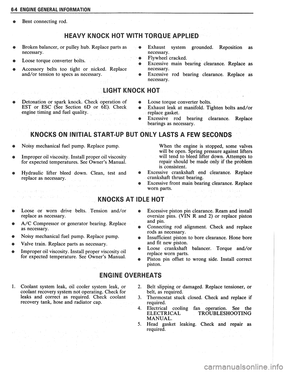
Bent connecting rod.
HEAVY KNOCK H0"FVVI"F TORQUE APPLIED
Broken balancer, or pulley hub. Replace parts as e Exhaust system grounded. Reposition as
necessary. necessary.
Loose torque converter bolts. Flywheel
cracked.
e Excessive main bearing clearance. Replace as
Accessory belts too tight or nicked. Replace
necessary.
and/or tension to specs as necessary.
e Excessive rod bearing clearance. Replace as
necessary.
LIGHT KNOCK HOT
Detonation or spark knock. Check operation of e Loose torque converter bolts.
EST or ESC (See Section
6D or 6E). Check e Exhaust leak at manifold. Tighten bolts and/or
engine timing and fuel quality.
replace gasket.
8 Excessive rod bearing clearance. Replace
bearings as necessary.
KNOCKS ON INITIAL START-UP BUT ONLY LASTS A FEW SECONDS
Noisy mechanical fuel pump. Replace pump.
When the engine is stopped, some valves
will be open. Spring pressure against lifters
Improper oil viscosity. Install proper oil viscosity will
tend to bleed lifter down. Attempts to
for expected temperatures. See Owner's Manual. repair
should be made only if the problem
is consistent.
Hydraulic lifter bleed down. Clean, test and @ Excessive crankshaft end clearance. Replace
replace as necessary. crankshaft
thrust bearing.
@ Excessive front main bearing clearance. Replace
worn parts.
KNOCKS AT IDLE HOT
Loose or worn drive belts. Tension and/or @ Excessive piston pin clearance. Ream and install
replace as necessary. oversize pins. (VIN R and 2) or replace piston
A/C Compressor or generator bearing. Replace and
pin.
as necessary.
e Connecting rod alignment. Check and replace
rods as necessary.
Noisy mechanical fuel pump. Replace pump.
8 Insufficient piston to bore clearance. Hone bore
Valve train. Replace parts as necessary. and
fit new piston.
@ Loose crankshaft balancer. Torque and/or
Improper oil viscosity. Install proper viscosity oil
replace worn parts.
for expected temperature4 See Owner" e Piston pin offset to wrong side. Install correct
ENGINE OVERHEATS
Coolant system leak, oil cooler system leak, or
2. Belt slipping or damaged. Replace tensioner, or
coolant recovery system not operating. Check for belt, as required.
leaks and correct as required. Check coolant
3. Thermostat stuck closed. Check and replace if
recovery tank, hose and radiator cap.
required.
4. Electrical cooling fan operation. See the
ELECTRICAL TROUBLESHOOTING
MANUAL.
5. Head gasket leaking. Check and repair as
required.
Page 365 of 1825
BA2-14 2.8 LITER V-6
bores for oversize valves use tool 5-5330-1, 2 or 3,
respectively.
VALVE SEATS
Reconditioning the valve seats is very important,
because the seating of the valves must be perfect for the
engine to deliver the power and performance designed
into it.
Another important factor is the cooling of the
valve heads. Good contact between each valve and its
seat in the head is imperative to insure that the heat in
the valve head will be properly carried away.
Several different types of equipment are available
for reseating valve seats. The recommendations of the
manufacturer of the equipment being used should be
carefully followed to attain proper results.
VALVES
Valves that are pitted can be refaced, to the
proper angle, insuring correct relation between the
head and stem, on a valve
refacing machine. Valve
stems which show excessive wear, or valves that are
warped excessively should be replaced. When a valve
head which is warped excessively is
refaced, a knife
edge will be ground on part or all of the valve head due
to the amount of metal that must be removed to
completely
reface the valve. Knife edges lead to
breakage, burning or preignition due to heat localizing
on this knife edge. If the edge of the valve head is less
than
.8mm thick after grinding, replace the valve.
Several different types of equipment are available
for
refacing valves. The recommendations of the
manufacturer of the equipment being used should be
carefully followed to attain the proper results.
Assembly
Insert a valve in the proper port.
Install a valve stem seal over the valve stem and
valve guide base inlet only.
Drop an oil shedder and valve rotator over the
exhaust and a valve spring cap over the valve
spring.
Using tool
5-8062 compress the valve spring.
Install the square cut
"0" ring around the valve
stem in the lower groove, making sure it is not
twisted.
Insert valve, stem key locks and release tool.
Install the valve locks and release the compressor
tool making sure that the locks seat properly in
the upper groove of the valve stem. Grease may
be used to hold the locks in place while releasing
the compressor tool.
Install the remaining valves.
Check each valve stem oil seal by placing valve
stem leak detector, tool J-23994, over the end of
the valve stem and against the cap. Operate the
vacuum pump and make sure no air leaks pass the
seal.
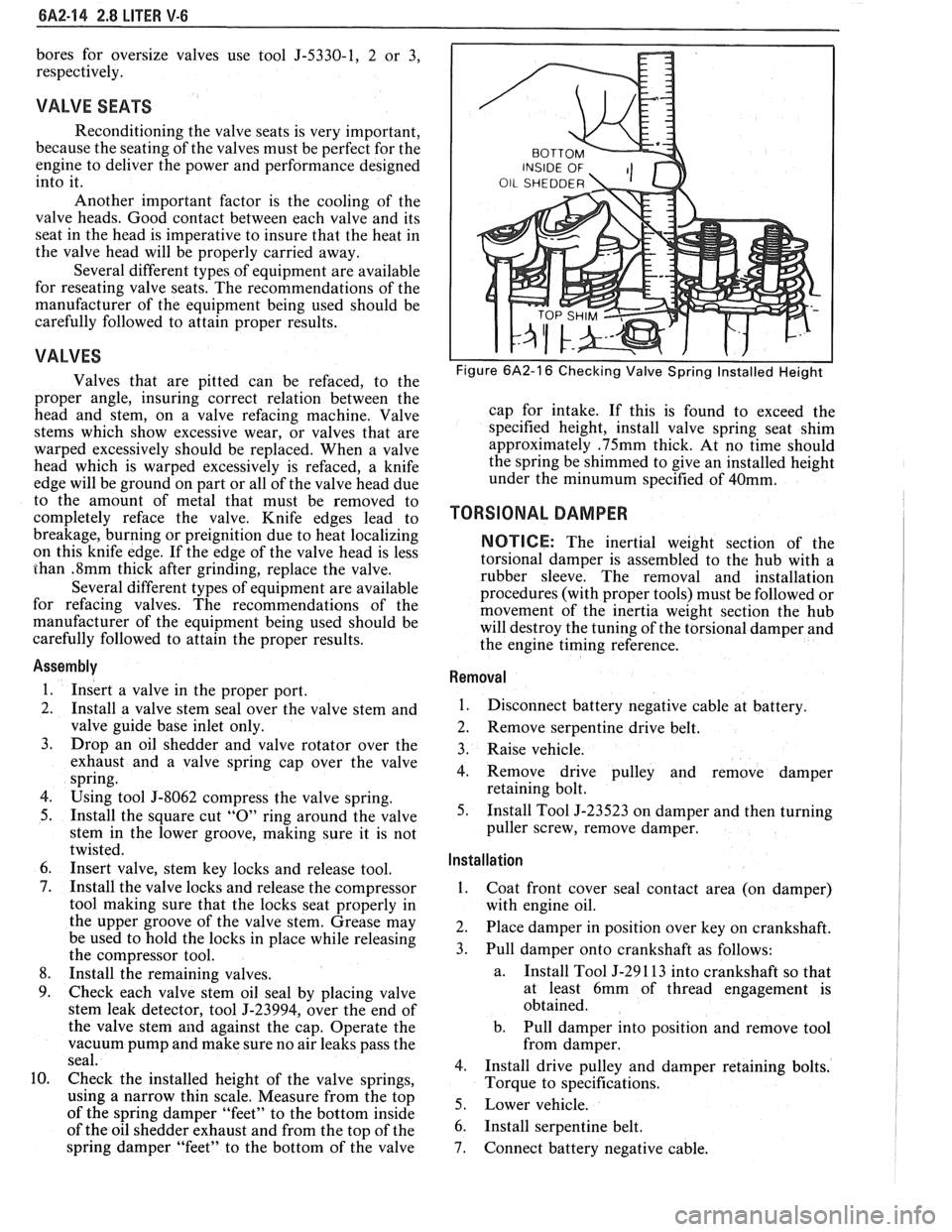
Check the installed height of the valve springs,
using
a narrow thin scale. Measure from the top
of the spring damper "feet" to the bottom inside
of the oil shedder exhaust and from the top of the
spring damper "feet" to the bottom of the valve
Figure 6A2-16 Checking Valve Spring Installed Height
cap for intake. If this is found to exceed the
specified height, install valve spring seat shim
approximately
.75mm thick. At no time should
the spring be shimmed to give an installed height
under the
minumum specified of 40mm.
TORSIONAL DAMPER
NOTICE: The inertial weight section of the
torsional damper is assembled to the hub with a
rubber sleeve. The removal and installation
procedures (with proper tools) must be followed or
movement of the inertia weight section the hub
will destroy the tuning of the torsional damper and
the engine timing reference.
Removal
1.
Disconnect battery negative cable at battery.
2. Remove serpentine drive belt.
3. Raise vehicle.
4. Remove drive pulley and remove damper
retaining bolt.
5. Install Tool J-23523 on damper and then turning
puller screw, remove damper.
Installation ,
1.
Coat front cover seal contact area (on damper)
with engine oil.
2. Place damper in position over key on crankshaft.
3. Pull damper onto crankshaft as follows:
a. Install
Tool J-29 1 13 into crankshaft so that
at least 6mm of thread engagement is
obtained.
b. Pull damper into position and remove tool
from damper.
4. Install drive pulley and damper retaining bolts.
Torque to specifications.
5. Lower vehicle.
6. Install serpentine belt.
7. Connect battery negative cable.
Page 366 of 1825
2.8 LITER V.6 6A2-15
18-30 N.m (13-22 FT. LBS.)
I 11 47-48 N.m (20-35 FT. LBS.) I
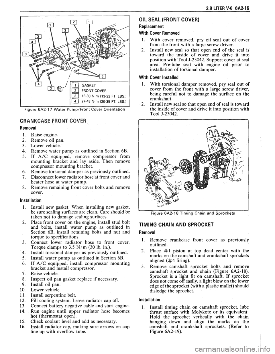
Figure 6A2-17 Water Pump/Front Cover Orientation
CRANKCASE FRONT COVER
Removal
1. Raise engine.
2. Remove oil pan.
3. Lower vehicle.
4. Remove water pump as outlined in Section 6B.
5. If A/C equipped, remove compressor from
mounting bracket and lay aside. Then remove
compressor mounting bracket.
6. Remove torsional damper as previously outlined.
7. Disconnect lower radiator hose at front cover and
heater hose at water pump.
8. Remove remaining front cover bolts and remove
cover.
Installation
1. Install new gasket. When installing new gasket,
be sure sealing surfaces are clean. Care should be
taken not to damage sealing surfaces.
2. Place front cover on the engine, install stud bolt
and bolts, install water pump as outlined in
Section 6B, install retaining bolts and nut and
torque to specifications.
3. Connect lower radiator hose to front cover.
Torque clamps to
3.5 N-m (30 lb. in.).
4. Install torsional damper as previously outlined.
5. Install water pump as outlined in Section 6B.
6. If A/C equipped, install compressor mounting
bracket and install compressor.
7. Raise vehicle.
8. Inspect oil pan gasket replace if necessary.
9. Install oil pan.
10. Lower vehicle.
11. Install serpentine belt.
12. Fill cooling system. Leave radiator cap off.
13. Connect battery negative cable and start engine.
14. Run engine until upper radiator hose becomes
hot (thermostat open).
15. Check coolant level and add as necessary.
16. Install radiator cap, making sure arrows on cap
line up with overflow tube.
OIL SEAL (FRONT COVER)
Replacement
With Cover Removed
1. With cover removed, pry oil seal out of cover
from the front with a large screw driver.
2. Install new seal so that open end of the seal is
toward the inside of cover and drive it into
position with Tool
5-23042. Support cover at seal
area. Pre-lube seal with engine oil prior to
installation of torsional damper.
With Cover Installed
1. With torsional damper removed, pry seal out of
cover from the front with a large screw driver,
being careful not to damage the surface on the
crankshaft.
2. Install new seal so that open end of seal is toward
the inside of cover and drive it into position with
To01 5-23042.
Figure 6A2-18 Timing Chain and Sprockets
TIMING CHAIN AND SPROCKET
Removal
1. Remove crankcase front cover as previously
outlined.
2. Place #1 piston at top dead center with the
marks on the camshaft and crankshaft sprockets
aligned (#4 firing).
3. Remove camshaft sprocket bolts and remove
camshaft sprocket and chain (Figure
6A2- 18).
Sprocket is a light fit on camshaft.
If sprocket
does not come off easily, a light blow on the lower
edge of the sprocket (with a plastic mallet) should
dislodge the sprocket.
Installation
1. Install timing chain on camshaft sprocket, lube
thrust surface with Molykote or its equivalent.
Hold the sprocket vertically with the chain
hanging down and align the marks on the
camshaft and crankshaft sprockets. (Refer to
Figure
6A2- 19).
Page 488 of 1825
DRIVEABILITY AND EMISSIONS 5.OL (VIN E) 6E2-3
........ FUEL METER COVER ASSEMBLY C2-7
FUEL INJECTOR ASSEMBLIES .......... C2-8
FUEL METER BODY ASSEMBLY ......... C2-9
..... THROTTLE POSITION SENSOR (TPS) C2-10
IDLE AIR CONTROL (IAC) VALVE ........ 62-1 1
THROTTLE BODY ASSEMBLY
.......... C2-11
MINIMUM IDLE SPEED CHECK .......... C2-12
... THROTTLE BODY INJECTION (TBI) UNIT C2-13
FUEL
HOSEIPIPE ASSEMBLIES .......... C2-13
Materials ...................... C2-13
Fuel Line Repair .................. C2-13
FUEL PUMP RELAY .................. C2-13
............... OILPRESSURESWITCH C2-13
PARTS INFORMATION ................. C2-14
Idle Air Control (IAC) Valve Check
Chart C-2C
..................... C2-16
SECTION C3
EVAPORATIVE EMISSION CONTROL SYSTEM
GENERAL DESCRIPTION
............... C3-1
........................ PURPOSE C3-1
VAPOR CANISTER
................... C3-1
EVAPORATIVE EMISSION SYSTEM
....... C3-1
IN-TANK PRESSURE CONTROL VALVE
. . C3-2
.... RESULTS OF INCORRECT OPERATION C3-2
........................ DIAGNOSIS C3-2
VISUAL CHECK OF CANISTER
.......... C3-2
CANISTER PURGE SOLENOID
.......... C3-2
ON-CAR SERVICE ................. C3-2
FUEL VAPOR CANISTER
R/R ............ C3-2
CANISTER HOSES
.................... C3-2
PARTS INFORMATION ................ C3-2
Canister Purge Valve Check
Chart C-3
...................... C3-4
SECTION
C4
IGNITION SYSTEM I EST
GENERAL DESCRIPTION
............... C4-1
PURPOSE ........................ C4-1
OPERATION ...................... C4-1
.. DIAGNOSIS ................... ... C4-1
RESULTS OF INCORRECT EST OPER ...... C4-1
HOW CODE 42 IS DETERMINED ....... C4-2
CODE12 ........................ C4-2
CHECKING EST PERFORMANCE ........ C4-2
ON-CAR SERVICE .................... C4-2
SETTINGTIMING .................. C4-2
PARTS INFORMATION ................ C4-2
Ignition System Check
Chart C-4
................... .. . C4-4
SECTION C5
ELECTRONIC SPARK CONTROL (ESC) SYSTEM
GENERAL DESCRIPTION
................ C5-1
PURPOSE ..*...................... C5-1
OPERATION
....................... C5-1
DIAGNOSIS
......................... C5-1
RESULTS OF INCORRECT ESC OPERATION
. C5-1
ON-CAR SERVICE
..................... C5-1 ESC
KNOCK SENSOR
................ C5-1
ESCMODULE
...................... C5-1
PARTS INFORMATION ................. C5-2
Electronic Spark Control (ESC) System Check
Chart C-5
...................... C5-4
SECTION C6
AIR INJECTION REACTION (A.I.R.) SYSTEM
GENERAL DESCRIPTION
............... C6-1
PURPOSE
.*....................... C6-1
OPERATION
...................... C6-1
AIR CONTROL PEDES VALVE .......... C6-1
RESULTS OF INCORRECT OPERATION
.... C6-2
DIAGNOSIS
........................ C6-2
OPERATIONAL CHECKS
.....*........ C6-2
AirPump ...................... C6-2
Hoses and Pipes
................. C6-3
Check Valve
.................... C6-3
ON-CAR SERVICE
.................... C6-3
DRIVEBELT ...................... C6-3
AIR INJECTION PUMP
............... C6-3
AIR INJECTION CONTROL
(PEDES) VALVE
.................. C6-3
AIR INJECTION CHECK VALVE ......... C6-4
PARTS INFORMATION
................ C6-4
AIR Management Check
. Pedes Valve
Chart C-6
..................... C6-6
SECTION C7
EXHAUST GAS RECIRCULATION (EGR) SYSTEM
GENERAL DESCRIPTION
............... C7-1
PURPOSE
........................ C7-1
OPERATION
...................... C7-1
EGRCONTROL
..................... C7-1
NEGATIVE BACKPRESSURE VALVE
...... C7-1
EGR VALVE IDENTIFICATION
.......... C7-2
RESULTS OF INCORRECT OPERATION
.... C7-2
DIAGNOSIS
......................... C7-2
ON-CAR SERVICE
..................... C7-2
EGRVALVE
....................... C7-2
EGR Manifold Passage
............. C7-2
EGR CONTROL SOLENOID
............. C7-3
PARTS INFORMATION
................. C7-3
Exhaust Gas Recirculation (EGR) Check
Chart C-7
...................... C7-4
SECTION
C8
TRANSMISSION CONVERTER CLUTCH
GENERAL DESCRIPTION
............... C8-1
PURPOSE
........................ C8-1
OPERATION
...................... C8-1
CIRCUIT DESCRIPTION
............... C8-1
RESULTS OF INCORRECT TCC
OPERATION
..................... C8-2
DIAGNOSIS
......................... C8-2
ON-CAR SERVICE .................... C8-2
PARTS INFORMATION ................. C8-2
Page 551 of 1825
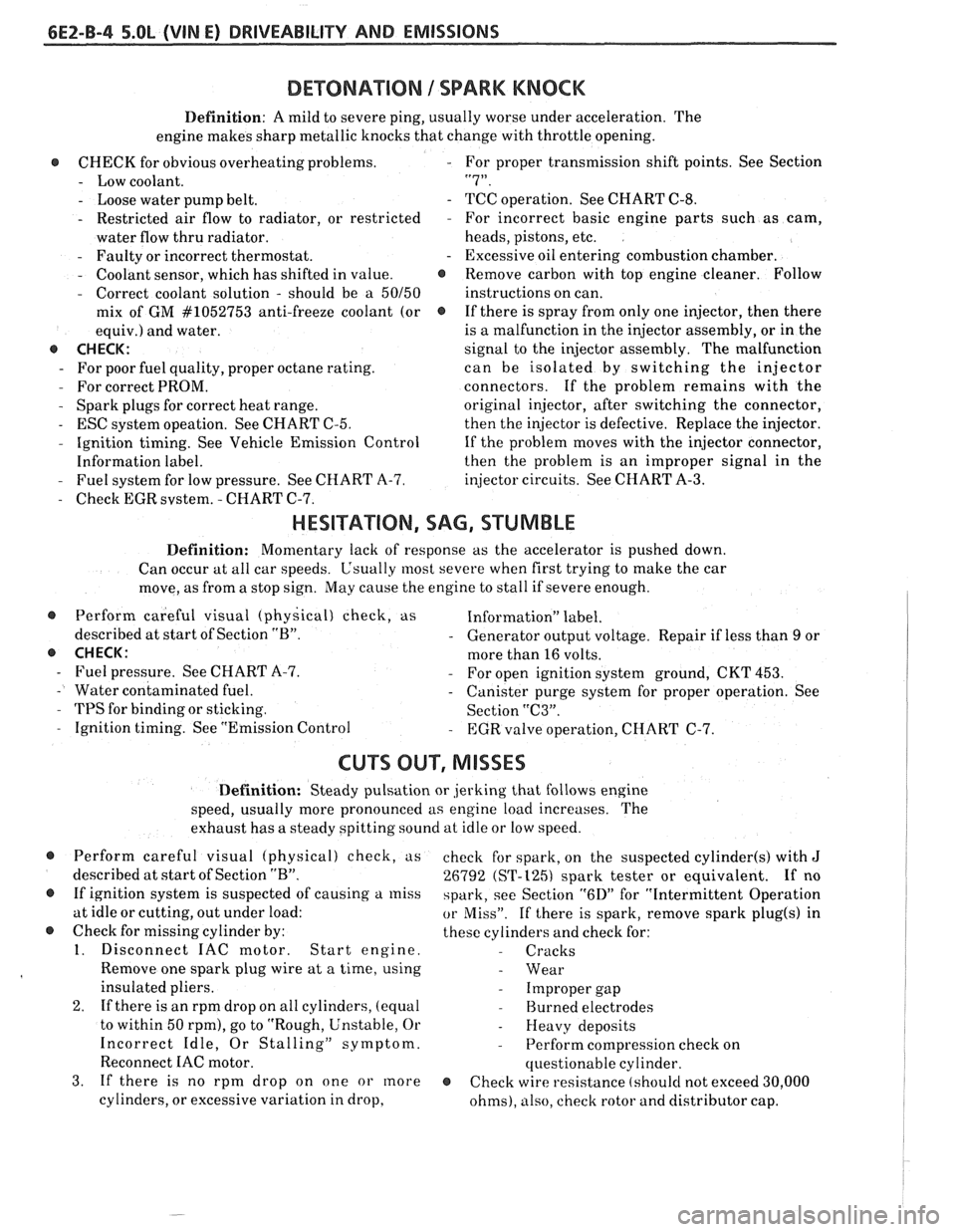
6EZ-B-4 5.OL (VIN E) DRIVEABILITY AND EMISSIONS
DEWNATION 1 SPARK KNOCK
Definition: A mild to severe ping, usually worse under acceleration. The
engine makes sharp metallic knocks that change with throttle opening.
@ CHECK for obvious overheatingproblems. - For proper transmission shift points. See Section
- Low coolant. "7".
- Loose water pump belt. - TCC operation. See CHART C-8.
- Restricted air flow to radiator, or restricted - For incorrect basic engine parts such as cam,
water flow thru radiator. heads,
pistons, etc.
- Faulty or incorrect thermostat. - Excessive oil entering combustion chamber.
- Coolant sensor, which has shifted in value. @ Remove carbon with top engine cleaner. Follow
- Correct coolant solution - should be a 50150 instructions on can.
mix of GM
#lo52753 anti-freeze coolant (or @ If there is spray from only one injector, then there
equiv.) and water. is
a malfunction in the injector assembly, or in the
@ CHECK: signal to the injector assembly. The malfunction
- For poor fuel quality, proper octane rating. can be isolated by switching the injector
- For correct PROM. connectors. If the problem remains with the
- Spark plugs for correct heat range.
original injector, after switching the connector,
- ESC system opeation. See CHART C-5.
then the injector is defective. Replace the injector.
- Ignition timing. See Vehicle Emission Control
If the problem moves with the injector connector,
Information label. then the
problem is an improper signal in the
- Fuel system for low pressure. See CHART A-7.
injector circuits. See CHART A-3.
- Check EGR svstem. - CHART C-7.
HESITATION, SAG, STUMBLE
Definition: Momentary lack of response as the accelerator is pushed down.
Can occur at all car speeds.
C'sually most severe when first trying to make the car
move, as from a stop sign.
May cause the engine to stall if severe enough.
@ Perform careful visual (physical) check, as Information" label.
described at start of Section
"B". - Generator output voltage. Repair if less than 9 or
@ CHECK: more than 16 volts.
- Fuel pressure. See CHART A-7. - For open ignition system ground, CKT 453.
- Water contaminated fuel. - Canister purge system for proper operation. See
- TPS for binding or sticking.
Section "C3".
- Ignition timing. See "Emission Control - EGR valve operation, CHART C-7.
CU"F OUT, MISSES
Definition: Steady pulsation or jerking that follows engine
speed, usually more pronounced as engine load increases. The
exhaust has a steady spitting sound at idle or low speed.
@ Perform careful visual (physical) check, us
described at start of Section
"B".
@ If ignition system is suspected of causing a miss
at idle or cutting, out under load:
@ Check for missing cylinder by:
1. Disconnect IAC motor. Start engine.
Remove one spark plug wire at a time, using
insulated pliers.
2. If there is an rpm drop on all cylinders, (equal
to within 50
rpm), go to "Rough, Unstable, Or
Incorrect Idle, Or Stalling" symptom.
Reconnect
IAC motor.
3. If there is no rpm drop on one or more
cylinders, or excessive variation in drop, check
for spark, on the suspected
cylinder(s) with J
26792 (ST-1251 spark tester or equivalent. If no
spark, see Section
"6D" for "Intermittent Operation
or Miss". If there is spark, remove spark plug(s) in
these cylinders and check for:
- Cracks
- Wear
- Improper gap
- Burned electrodes
- Heavy deposits
- Perform compression check on
questionable cylinder.
@ Check wire resistance (shoulcl not exceed 30,000
ohms), also, check rotor and distributor cap.
Page 648 of 1825
DRlVEABlLlTVAND EMISSIONS 2.8L (VIN S). 5.OL (VIN F) & 5.7L (VIN 8) 6E3-3
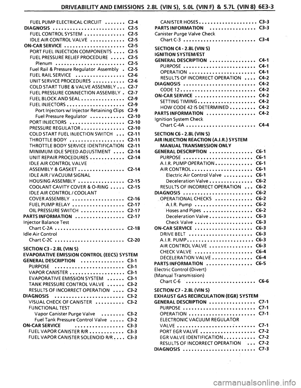
.................... FUEL PUMP ELECTRICAL CIRCUIT ....... C2-4 CANISTER HOSES C3-3
................ DIAGNOSIS ......................... C2-5 PARTS INFORMATION C3-3
FUEL CONTROL SYSTEM .............. C2-5 Canister Purge Valve Check
......................... IDLE AIR CONTROL VALVE ............ C2-5 Chart C-3 C3-4
ON-CAR SERVICE
..................... C2-5
.... PORT FUEL INJECTION COMPONENTS C2-5
FUEL PRESSURE RELIEF PROCEDURE ..... C2-5
Plenum ........................ C2-5
Fuel Rail & Pressure Regulator Assembly . C2-5
FUEL RAIL SERVICE ................. C2-6
UNIT SERVICE PROCEDURES ........... C2-6
COLD START TUBE & VALVE ASSEMBLY ... C2-7
FUEL PRESSURE CONNECTION ASSEMBLY . C2-7
FUEL BLOCK AND SEAL ............... C2-9
FUEL INJECTORS .................... C2-9
Port Injectors wl Injector Retaining Clips C2-9
Fuel Pressure Regulator ............ C2-10
PORT INJECTORS ................... C2-10
PRESSURE REGULATOR ............... C2-10
COLD START FUEL INJECTION SWITCH ...
THROTTLE BODY ...................
THROTTLE BODY SERVICE IDENTIFICATION
MINIMUM IDLE SPEED ADJUSTMENT
....
UNIT REPAIR PROCEDURES ............
IDLE AIR CONTROL VALVE
ASSEMBLY
& GASKET ................
IDLE AIR I VACUUM SIGNAL
HOUSING ASSEMBLY
................
COOLANT CAVITY COVER & O-RING .....
IDLE AIR CONTROL I COOLANT
COVER ASSEMBLY
..................
FUEL PUMP RELAY ..................
OIL PRESSURE SWITCH ...............
PARTS INFORMATION .................
Injector Balance Test
Chart C-2A
........................
Idle Air Control
Chart C-2C
........................
SECTION C3 . 2.8L (WIN S)
EVAPORATIVE EMISSION CONTROL (EECS) SYSTEM
GENERAL
DESCRIPTION ............... C3-1
PURPOSE ........................ C3-1
VAPOR CANISTER ................... C3-1
EVAPORATIVE EMISSION SYSTEM ...... C3-1
TANK PRESSURE CONTROL VALVE ...... C3-2
.... RESULTS OF INCORRECT OPERATION C3-2
DIAGNOSIS
........................ C3-2
VISUAL CHECK OF CANISTER .......... C3-2
FUNCTIONAL TEST
Vapor Canister Purge Valve
........ C3-2
..... Fuel Tank Pressure Control Valve C3-2
ON-CAR SERVICE
................. C3-3
FUEL VAPOR CANISTER WR ............ C3-3
FUEL VAPOR CANISTER SOLENOID WR .... C3-3
SECTION C4 . 2.8L (VIN S)
IGNITION
SQSTEMIEST
................ GENERAL DESCRIPTION C4-1
......................... PURPOSE C4-1
OPERATION ....................... C4-1
RESULTS OF INCORRECT OPERATION .... C4-2
DIAGNOSIS
......................... C4-2
CODE 12 .......................... C4-2
ON-CAR SERVICE ..................... C4-2
SETTING TIMING .................... C4-2
HOW CODE 42 IS DETERMINED ......... C4-2
PARTS INFORMATION ................. C4-2
Ignition System Check
Chart C-4A
........................ C4-4
SECTION C6 . 2.8L (VIN S)
AIR INJECTION REACTION (A.I.R.) SYSTEM
MANUAL TRANSMISSION ONLY
............... GENERAL DESCRIPTION C6-1
........................ PURPOSE C6-1
............. A.I.R. PUMP OPERATION C6-I
..................... AIR CONTROL C6-1
.......... Electric Air Control Valve C6-1
............... Deceleration Valve C6-2
... RESULTS OF INCORRECT OPERATION C6-2
........................ DIAGNOSIS C6-2
............. OPERATIONAL CHECKS C6-2
.................... A.I.R. Pump C6-2
................. Hoses and Pipes C6-2
............... Deceleration Valve C6-3
.................... Check Valve C6-3
.................... ON-CAR SERVICE C6-3
...................... DRIVEBELT C6-3
....................... A.I.R. PUMP C6-3
............... AIR CONTROL VALVE C6-3
.................... CHECKVALVE C6-4
DECELERATION VALVE .............. C6-4
................ PARTS INFORMATION C6-5
Electric Control (Divert)
(Manual Transmission)
........................ Chart C-6 C6-6
SECTION C7
. 2.8L (VIN S)
EXHAUST GAS RECIRCULATION (EGR) SYSTEM
GENERAL DESCRIPTION
................ C7-1
......................... PURPOSE C7-1
....................... OPERATION C7-I
ELECTRONIC VACUUM REGULATOR
........................... VALVE C7-1
................... PORT EGR VALVE C7-2
........... EGR VALVE IDENTIFICATION C7-2
... RESULTS OF INCORRECT OPERATION C7-2
......................... DIAGNOSIS C7-3
Page 651 of 1825
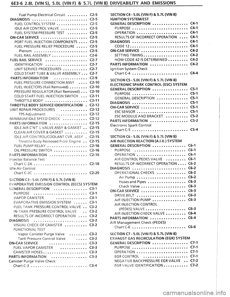
6E3-6 2.8L (VIN S). 5.OL (&BIN F) & 5.7L (WIN 8) BRllVEABlhlPY AND EMISSIONS
......... Fuel Pump Electrical Circuit C2-5
DIAGNOSiS ......................... CZ-5
.............. FUEL CONTROL SYSTERA C2.5
............ IDLE AIR CONTROLVALVE CZ-5
......... FUEL SYSTEM PRESSURE TEST C2-5
ON-CAR SERVICE ..................... C2-5
PORT FUEL INJECTION COMPONENTS .... Cf-5
FUEL PRESSURE RELIEF PROCEDURE ..... C2-5
Plenum ......................... C2-5
................ FUEL RAILASSEMBLY CP-6
FUEL RAIL SERVICE ................... C2-7
................... IDENTIFICATION C2-7
........... UNIT SERVICE PROCEDURES C2-7
COLD START .TUBE & VALVE ASSEMBLY ... ~2-7
PARTS INFORMATION ............... CZ-9
.... FUEL PRE5Si.J RE COPdNECl'ION ASSY C2-10
FUEL INJECTORS (Rail Removed) ........ C2-10
PRESSURE REGULATOR (Ball Removed) ... C2-10
COLD START FUEL INJEClION SWITCH ... C2-1%
THROTTLE BODY ................... CZ-11
VWROTTLE BODY SERVICE IDENTIFICATION . C2-12
............ UNIT REPAIR PROCEDURES Cf-112
TPS Adjcistment .............. C2-12
MiNIRilUM IDLE SPEED CHECK ........... CE-'I2
................. PARTS INFORMATION C2-15
IDLE AIR C'NT' L VALVE ASSY (3r: GASKET . . C2-15
CLEAN AIR COVER & GASKET .......... C2-15
SECTION C4 . 5.0h (VIN F) & 5.7L (VIN 8)
lGNITlON SYSTEMIEST
................ GENERAL DESCRIPTION C4-1
......................... PURPOSE C4-1
OPERATION ....................... C4-1
RESULTS OF INCORRECT OPERATION .... C4-1
......................... DIAGNOSIS C4-1
CODE 12 .......................... C4-1
ON-CAR SERVICE ..................... C4-2
SETTING TIMING .................... C4-2
HOW CODE 42 IS DETERMINED ......... C4-2
................. PARTS INFORMATION C4-2
lgn~tion System Check
Chart C-4
......................... C4-4
SECTION C5 . 5.0L (VIM F) & 5.7L JVIN 8)
ELECTRONIC SPARK CONTROL (ESC) SYSTEM
................ GENERAL DESCRIPTION C5-1
......................... PURPOSE C5-1
.............. GENERAL DESCRIPTION C5-1
......................... DlAGNOSiS C5-1
..................... ON-CAR SERVICE C5-1
....................... ESCSENSOR 65-1
.......... E4C MODULE AiYD BRACKET 165-2
................. PARTS INFORMATXBM C5-2
Electronic Spark Control
Chiirt C-5 ......................... C5-4
IDLE AIR CBi\~TROVCOOLANl'CVR . AS57 0
Throlrle Body Reinovecl Froti.1 Engine . .
FUEL PUlVlP RELAY ..................
................ OIL PRESSURE 5WETCI-I
P/%RVS INFORMATION .................
Irilector Halarlce Test
Chart
C-2A ........................
Idle Air Control
Chart
C-%C ........................
C2-I 5 SECYlOM Ct; . 5.0L (VlN F) & 5.7L (VIN 8)
62-1 5 A8W INJECTION REACTION (A.I.R.) SYSTEM
C2-16 GENERAL DESCRbPTION ............... CG-I
C2-16 PURPOSE ....................... C6-1
C2-76 OPE RATION ...................... C6-1
AIR COPJTROL PEDES VALVE ......... C6-I
C2-'18 RESULTS OF INCORRECT OPERATION .... C6-2
DIAGNOSIS ........................ C6-2
............. Cf -20 OPERATIONAL CHECKS C6-2
SbCTIBN C3 . 5.0L (VIN F) h 5.7L (V1N 8)
I:itAPORAIIVE EMISSlON CONTROL (EECS) SYSTEM
LZNERA. L DESCRIP'rION ............... C3-'!
PURPOSE ........................ C3-1
VAPOR CANISTER
.............. $3-1
EVAF'OFt/?ITIVE EMISSION SYSTEM .me.e. C3-4
FUEL TANK PRESSURE CONTROL VALVE . . C3-2
IN-'TANK PRESSURE CONTROL VALVE . . 63-2
RESULTS OF IRiCORRECT OPERATIGN .... C3-2
DIAGNOSIS ........................ C3-2
VISUAL CHECK OF CANIS'rkR .......... C3-2
FUNCPIONAL TEST
Vapor
Can~saer Purge Valve ........ C3-9
Tank Pressure Control Valve ..... C3-2
ON-CAR SERVICE ................. C3-3
FUEL VAPOR CANISTER ............ C3-3
CANISTER HOSES.
................... C3-3
PARTS INFORiblAT%BN ................ C3-3
Canister Purge Valve Check
Chart
C-3 ......................... C3-4
...................... Air Pump C6-2
................. Hoses and Pipes C6-3
.................... Check \/alve C6-3
.................... ON-CAR SERVICE C6-3
...................... DRIVE BELT C6-3
AIR INJECTION PUMP ............... C6-3
AIR INJECTION CONTROL
.................. (PEDES) VALVE C6-3
AIR ~NJECTION CIIECK VALVE ......... ~6-4
................ PARTS INFORMATION C6-4
AIR Management Check (PEDES)
........................ Chart C-6 C6-6
SECTlON C7 . 5.OL (VlN F) & 5.7L (VIN 8)
EXHAUST GAS RECIRCULATION {EGR) SYSTEM
GENERAL DESCRIPI'ION ..............*. C7-1
......................... PURPOSE C7-I
OPERATION
....................... C7-1
EGR
CONTROL .................... C7-1
NEGATIVE BACKPRESSURE EGR VALVE . . C7-2
EGR \/ALVE IDEhITIFICATION ........... C7-2
Page 713 of 1825
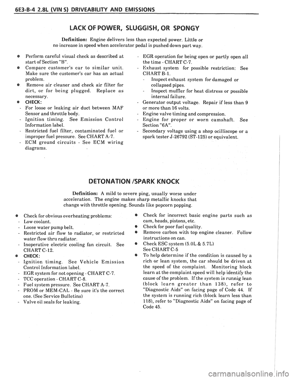
&E3-B-4 %.8L (VIN S) DRIVEABILITY AND EMISSIONS
LACK OF POWER, SLUGGISH, OR SPONGY
Definition: Engine delivers less than expected power. Little or
no increase in speed when accelerator pedal is pushed down part way.
Perform careful visual check as described at
- EGR operation for being open or partly open all
start of Section
"B". the time - CHART C-7.
e Compare customer's car to similar unit. - Exhaust system for possible restriction: See
Make sure the customer's car has an actual CHART
B-1,
problem.
@ Remove air cleaner and check air filter for
dirt, or for being plugged. Replace as
necessary.
@ CHECK:
- For loose or leaking air duct between MAF
Sensor and throttle body.
- Ignition timing. See Emission Control
Information label.
- Restricted fuel filter, contaminated fuel or
improper fuel pressure. See CHART A-7.
- ECM ground circuits - See ECM wiring
diagrams.
- Inspect exhaust system for damaged or
collapsed pipes.
- Inspect muffler for heat distress or possible
internal failure.
- Generator output voltage. Repair if less than 9
or more than 16 volts.
- Engine valve timing and compression.
- Engine for proper or worn camshaft. See
Section
"6A".
- Secondary voltage using a shop ocilliscope or a
spark tester
5-26792 (ST-125) or equivalent.
DETONATION ISPARK KNOCK
Definition: A mild to severe ping, usually worse under
acceleration. The engine makes sharp metallic knocks that
change with throttle opening. Sounds like popcorn popping.
@ Check for obvious overheating problems:
- Low coolant.
- Loose water pump belt.
- Restricted air flow to radiator, or restricted
water flow thru radiator.
- Inoperative electric cooling fan circuit. See
CHART C-12.
@ CHECK:
- Ignition timing. See Vehicle Emission
Control Information label.
- EGR system for not opening - CHART C-7.
- TCC operation - CHART C-8.
- Fuel system pressure. See CHART A-7.
- PROM or MEM-CAL - Be sure it's the correct
one. (See Service Bulletins)
- Valve oil seals for leaking.
@ Check for incorrect basic engine parts such as
cam, heads, pistons, etc.
@ Check for poor fuel quality.
@ Remove carbon with top engine cleaner. Follow
instructions on can.
@ Check ESC system (5.OL & 5.7L)
See CHART C-5
o To help determine if the condition is caused by a
rich or lean system, the car should be driven at
the speed of the complaint.
Monitoring block
learn at the complaint speed will help identify the
cause of the problem.
If the system is runnig lean
(block learn greater than
1381, refer to
"Diagnostic Aids" on facing page of Code 44.
If
the system is running rich (block learn less than
l18), refer to "Diagnostic Aids" on facing page of
Code 45.