1988 PONTIAC FIERO clock reset
[x] Cancel search: clock resetPage 750 of 1825

DRIVEABILITY AND EMISSIONS 2.8L (VIN S) 6E3-CZ-15
NOTICE: Before instal ling new idle air control valve
assembly, the position of its pintle
MUST
be checked. If pintle is extended too far,
damage to the assembly may occur.
Measure
@ Distance from gasket mounting surface of IAC
valve assembly
(70) to tip of pintle, Dimension
"A" in Figure
C2-19.
Adjust
If distance is greater that 28 mm (1 118 in.), reduce -
it as follows:
a. If
IAC valve assembly has
a "collar" around
electrical connector end, use firm hand pressure
on pintle to retract it. (A slight side-to-side motion
may help.)
b. If IAC valve assembly has "no collar", compress
pintle-retaining spring toward body of the IAC
and try to turn pintle clockwise.
@ If pintle will turn, continue turning until
28mm
(1 118 in.) is reached. Return spring to
original position, with straight part of spring
end lined up with flat surface under the pintle
head.
@ If pintle will not turn, use firm hand pressure
to retract it.
Install or Connect
1. New IAC valve assembly gasket (71) on IAC valve
assembly
(70).
2. IAC valve assembly in idle airlvacuum signal
housing assembly
(60).
Tighten
IAC valve assembly to 18N.m (13 ft. Ibs.), with
wrench on hex surface only.
3. Electrical connector at IAC valve assembly (70).
Important
No physical adjustment is made to the IAC
assembly after installation.
IAC resetting occurs
after reinstallation on the vehicle, and is reset
after the engine is started and then the ignition
turned off.
IDLE AIR / VACUUM SIGNAL HOUSING
ASSEMBLY
(With
IAC Removed) (Figure C2-20)
Remove or Disconnect
1. Idle airlvacuurn signal assembly attaching screw
assemblies
(65) and (66).
2. Idle airlvacuum signal housing assembly (60).
3. Idle airlvacuum signal assembly gasket (67).
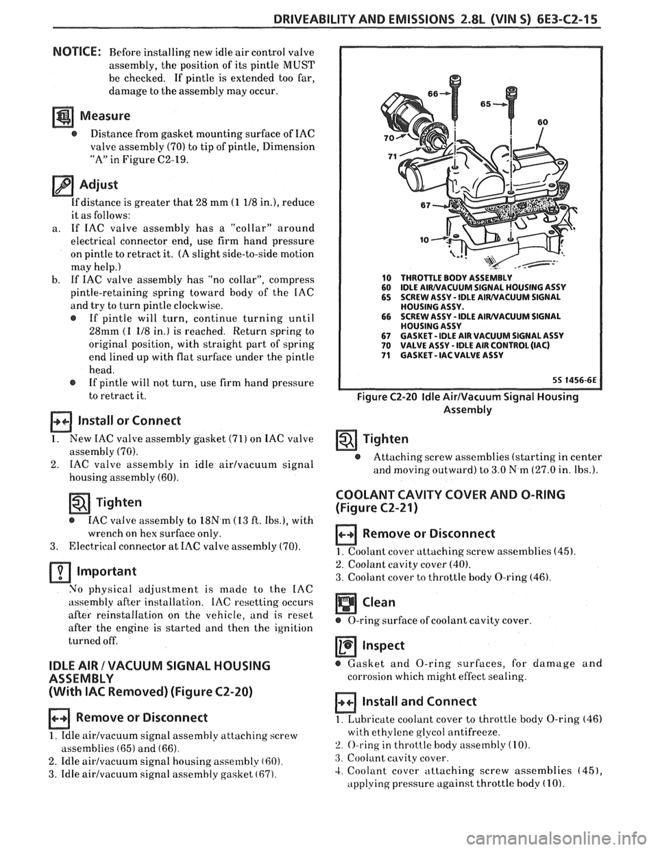
10 THROTTLE BODY ASSEMBLY
60 IDLE AIWVACUUM SIGNAL
HOUSING ASSY
65 SCREW ASSY - IDLE AIWVACUUM SIGNAL
HOUSING ASSY.
66 SCREW
ASSY
- IDLE AIWVACUUM SIGNAL
HOUSING ASSY
67 GASKET - IDLE AIR VACUUM SIGNAL ASSY 70 VALVE ASSY - IDLE AIR CONTROL (IAC) 71 GASKET - IAC VALVE ASSY
Figure C2-20 Idle AirIVacuum Signal Housing
Assembly
Tighten
@ Attaching screw assemblies (starting in center
and
moving outward) to 3.0 N.m (27.0 in. Ibs.).
COOLANT CAVITY COVER AND O-RING
(Figure
C2-21)
Remove or Disconnect
1. Coolant cover attaching. screw assemblies (45).
2. Coolant cavity cover (40).
3. Coolant cover to throttle body O-ring (46).
Inspect
@ Gasket and O-ring surfaces, for damage and
corrosion which might effect sealing.
Install and Connect
1. Lubricate coolant cover to throttle body O-ring (46)
with ethylene glycol antifreeze.
2. O-ring in throttle body assembly (10).
:3. Coolant cavity cover.
4. Coolant cover attaching screw assemblies (451,
applying pressure against throttle body (1 0).
Page 1556 of 1825

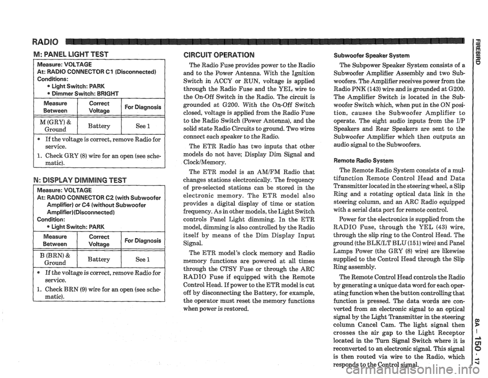
M: WNEL LIGHT TEST GlRGUlT OPERATION Subwoofer Speaker System
TOR 61 (Disconnected)
If the voltage is correct, remove Radio for
N: DISPLAY DIMMING TEST
TOW 62 (with Subwoofer
The Radio Fuse provides power to the Radio
and to the Power Antenna. With the Ignition
Switch in ACCY or RUN, voltage is applied
through the Radio Fuse and the
UEL wire to
the On-Off Switch in the Radio. The circuit is
grounded at 6200. With the On-Off Switch
closed, voltage is applied from the Radio Fuse
to the Radio Switch (Power Antenna), and the
solid state Radio Circuits to ground. Two wires
connect each speaker to the Radio.
The ETR Radio has two inputs that other
models do not have; Display Dim Signal and
ClocklMemory.
The ETR model is an AMIFM Radio that
changes stations electronically. The frequency
of pre-selected stations can be stored
in the
electronic memory. The ETR model also
provides a digital display of time or station
frequency. As in other models, the Light Switch
controls Panel Light dimming. In the
ETR
model, g is also controlled by the Radio
itself by means of the Dim Display Input
Signal.
The ETR model's clock memory and Radio
memory functions are powered at all times
through the CTSY Fuse or through the ARC
RADIO Fuse if equipped with the Remote
Control Head. If power to the ETR model is cut
off by disconnecting the Battery, for example,
the operator must reset the memory functions
when power is restored. The
Subpower Speaker
System consists of a
Subwoofer Amplifier Assembly and two Sub-
woofers. The Amplifier receives power from the
Radio PNK
(143) wire and is grounded at 6200.
The Amplifier Switch is located in the
Sub-
woofer Switch which, when put in the ON posi-
tion, causes the Subwoofer Amplifier to
operate. The eight audio inputs from the
I/P
Speakers and Rear Speakers are sent to the
Subwoofer Amplifier which then outputs an
audio signal to the Subwoofers.
Remote Radio System
The Remote Radio System consists of a mul-
tifunction Remote Control
Head and Data
Transmitter located in the steering wheel, a Slip
Ring and a rotating optical data link in the
steering
colurnn, and an ARC Radio equipped
with a serial data port for remote control.
Power for the electronics is supplied from the
RADIO Fuse, through the
YEL (43) wire,
through the slip ring to the Control Head. The
ground (the
BLKLT BLU (15 1) wire) and Pand
Larnps Power (the GRY (8) wire) are Likewise
supplied to the Control Head through the Slip
Ring assembly.
The Remote Control Head controls the Radio
by generating a unique data word for each oper-
ating function when the button controlling that
function is pressed. The data words are con-
verted from an electronic signal to an optical
signal by the Light Transmitter in the steering
column Cancel Cam. The light signal then
crosses the air gap to the Light Receptor
located in the
Turn Signal Switch where it is
reconverted to
an electronic signal. This signal
is then routed via wire to the Radio, which
responds to the Control signal.
Page 1650 of 1825

RADIO SYSTEMS AND ANTENNAS 9A-1
SECTION 9A
0 SYSTEMS AND ANTENNAS
CONTENTS
............................................. General Description .................................... 9A-1 Radio Operation 9A-4
Radio
............................................................ 9A-1 ETR AM/FM Stereo (UM-7) ....................... 9A-4
Antennas
........................................................ 9A- 1 ETR Stereo Cassette (UM-6) ......................... 9A-5
Fixed Antenna
.......................................... 9A- 1 ETR Stereo/Cassette/Eaualizer
Diagnosis ........................................................
Radio ....................... .. ................................
Static and Noise .................................... .....
........................................ Popping Noise
Preliminary Diagnostics
.............................
Antenna ................................. .. ................
Tape Player .................. .... .......................
Service Procedures ....................................
Radio and Speakers ........................... .............
Radio Noise Suppression Equipment ............
Stereo Cassette Tape Player ..........................
Tape & Tape Player Care ........................
(UX-1) ..................................................... 9A-6
Advanced ETR
Stereo/Cassette/Equalizer Touch
Control
.................................... ... .............. 9A-7
On-Car Service .............................................. 9A-9
Radio Receiver
............................................ 9A-9
Radio Steering Wheel Controls
..................... 9A-9
Audio Amplifier
........................................... 9A-9
Radio Suppression
..................................... 9A-9
Front Speaker
................................................. 9A-9
............... Rear Speaker; Sub Woofer Speaker
9A-9
Antenna
..................... .. ............................. 9A- 10
GENERAL DESCRIPUION
RADIO ANTENNAS
For radios and radio use see the "Radio Fixed Antenna
Operation" section. ETR means 'Electronically Tuned The
fixed antenna on the right front fender
Receiver'. cannot be adjusted up or down. It may provide
improved reception in rural areas.
- The fixed antenna is designed to withstand most
car washes without damage. If the antenna becomes
slightly bent, you can straighten it by hand. The
antenna can be replaced if severely bent (by vandalism,
etc.). Antennas must be kept clean for good
performance.
RADIO
Because radio problems are normally repaired at
authorized warranty repair stations, the tendency is to
remove the set when a problem is reported, without any
preliminary diagnosis. This results in a large number
of radios being "No Trouble Found" units when
received by the warranty repair stations. Often the
trouble can be corrected without radio removal. wire.
If equipped with
A/C, the blower motor has a
built-in capacitor. Extra electrical equipment added to
the static if not properly grounded or wiring was
improperly routed.
Weak
FM station reception will be affected by
nearby buildings, car speed and direction. These
"flutter" and "fading" conditions are characteristic of
weak FM signals.
ETR radios require clock and button reset if the
battery is disconnected.
Popping Noise
Static and Noise Operating devices such as turn signals, pushing in
cigarette lighter, operating stop lights, etc., may cause
Ground strap connections must be clean and
a popping noise on distant (weak) AM signals.
tight, spark plug cables must be TVRS type and in
good condition and resistance-type spark plugs used.
Preliminary Diagnostics
Capacitors are used in the generator, heating/air
conditioning system, and fuse panel to reduce noise
The inconvenience of driving without a radio
entering the radio through the feed wires. If the car has
while the set is being serviced can often be avoided if
a heater only, the capacitor is in the blower motor feed
the following quick checks are used to eliminate