1988 PONTIAC FIERO wheel
[x] Cancel search: wheelPage 2 of 1825
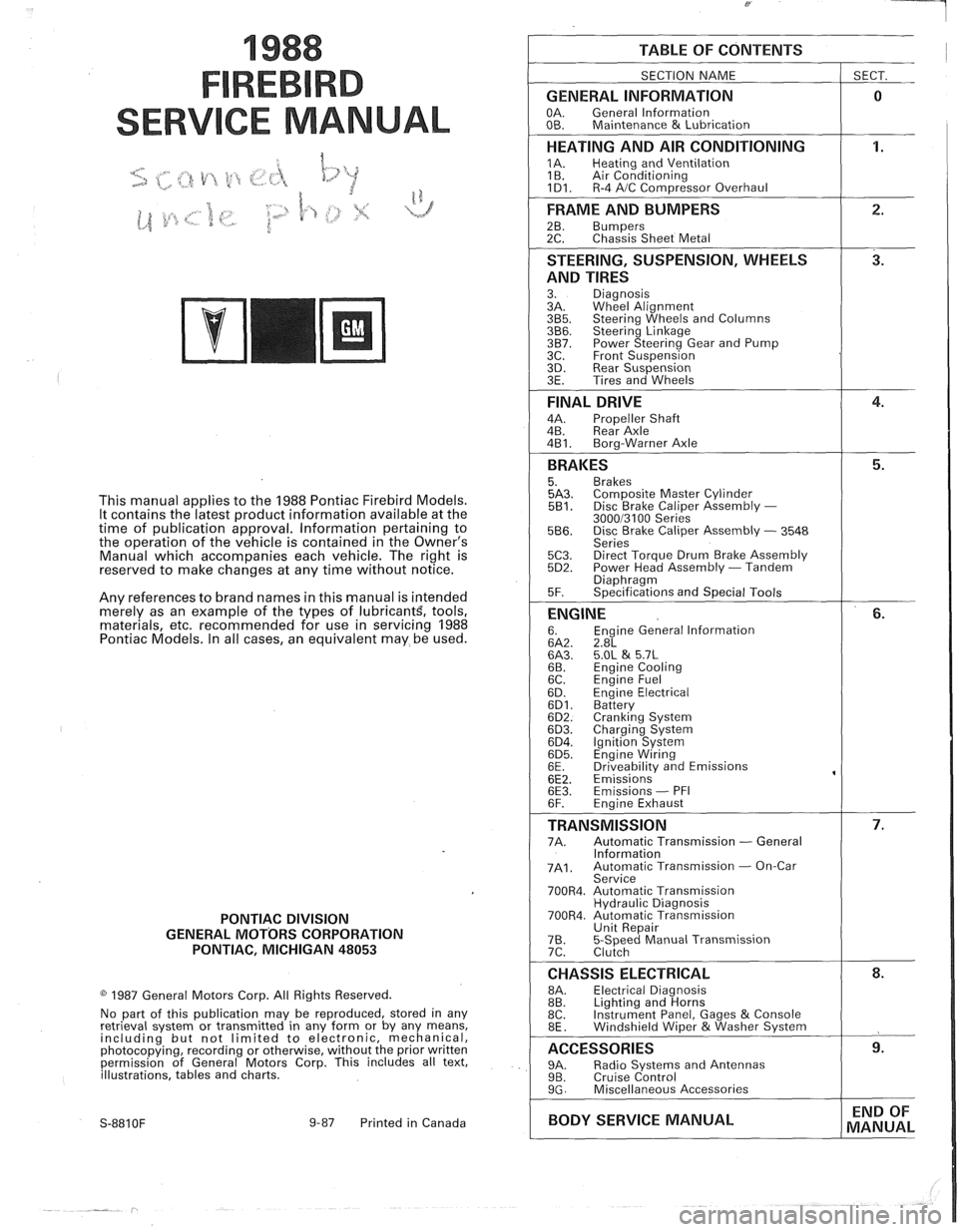
1988
SER
This manual applies to the 1988 Pontiac Firebird Models.
It contains the latest product information available at the
time of publication approval. lnformation pertaining to
the operation of the vehicle is contained in the Owner's
Manual which accompanies each vehicle. The right is
reserved to make changes at any time without notice.
Any references to brand names in this manual is intended
merely as an example of the types of
lubricant% tools,
materials, etc, recommended for use in servicing 1988
Pontiac Models. In all cases, an equivalent may be used.
PONTIAC DIVISION
GENERAL
MOTORS CORPORATION
PONTIAC, MICHIGAN 48053
1987 General Motors Corp. All Rights Reserved.
No part of this publication may be reproduced, stored in any
retrieval system or transmitted in any form or by any means,
including but not limited to electronic, mechanical,
photocopying, recording or otherwise, without the prior written
permission of General Motors Corp. This includes all text,
illustrations, tables and charts.
S-881 OF 9-87 Printed in Canada
TABLE OF CONTENTS
SECTION NAME
GENERAL INFORMATION
OA. General lnformation
OB. Maintenance & Lubrication
1 SECT.
HEATING AND AIR CONDITIONING
1A. Heating and Ventilation
1 B. Air Conditioning
1D1. R-4 AIC Com~ressor Overhaul
FRAME AND BUMPERS
2B. Bumpers 2C. Chassis Sheet Metal
STEERING, SUSPENSION, WHEELS
AND TIRES
3. Diagnosis
3A. Wheel Alignment
3B5. Steering Wheels and Columns 3B6. Steering Linkage 3B7. Power Steering Gear and Pump
3C. Front Suspension
3D. Rear Suspension
3E. Tires and Wheels
FINAL DRIVE
4A. Propeller Shaft
4B. Rear Axle
4B1. Bora-Warner Axle
BRAKES 5. Brakes 5A3. Comoosite Master Cvlinder 5B1. Disc r rake Caliper ~ssembly - 300013100 Series 5B6. Disc Brake Caliper Assembly - 3548
Series
5C3. Direct Torque Drum Brake Assembly 5D2. Power Head Assembly - Tandem Diaohraam 5F. ~~ecifications and Special Tools
ENGINE 6. Engine General lnformation 6A2. 2.8L 6A3. 5.OL & 5.7L 6B. Engine Cooling
6C. En~ine Fuel
6D. ~ngine Electrical 6D1. Battery 6D2. Cranking System 6D3. Charging System 6D4. Ignition System 6D5. Engine Wiring
6E. Driveabilitv and Emissions
6E2. ~missions' 6E3. Emissions - PFI
6F. Engine Exhaust
TRANSMISSION 7A. Automatic Transmission - General
lnformation
7A1. Automatic Transmission - On-Car
Service
700R4. Automatic Transmission Hydraulic Diagnosis
700R4. Automatic Transmission Unit Repair
76. 5-Speed Manual Transmission
7C. Clutch
CHASSIS ELECTRICAL 8A. Electrical Diagnosis
8B. Lighting and Horns
8C. Instrument
Panel, Gages
& Console
8E. Windshield Wiper &Washer System
ACCESSORIES 9A. Radio Systems and Antennas 9B. Cruise Control 9G. Miscellaneous Accessories
I BODY SERVICE MANUAL END
OF
MANUAL
Page 8 of 1825
GENERAL INFORMATION OA-5
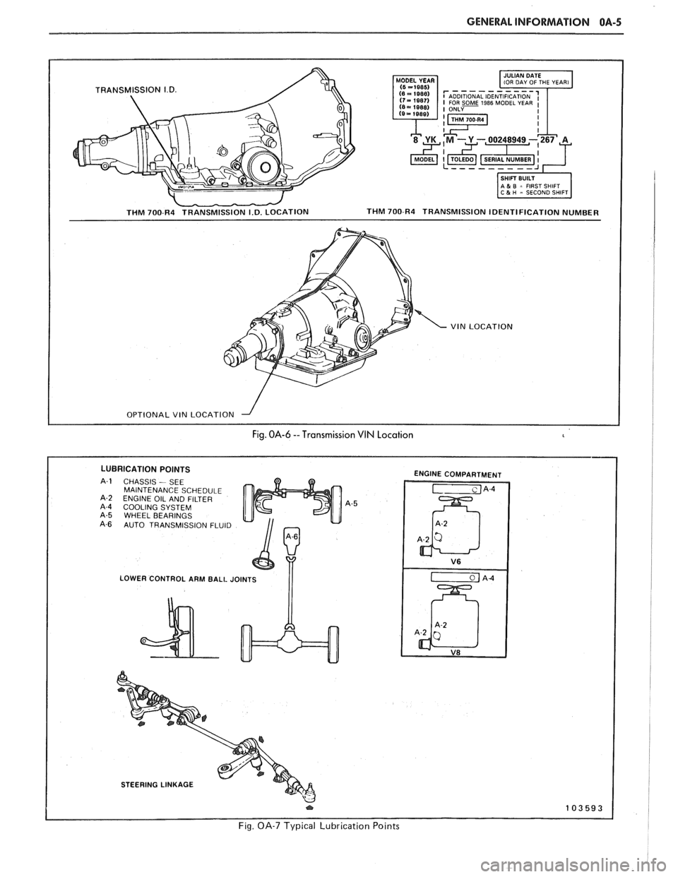
- THM 700-R4 TRANSMISSION I.D. LOCATION
1-1 IOU DAY OF THE YEAR1
I SHIFT BUILT 1 1 A & B = FIRST SHIFT 1 C 5 H - SECOND SHIFT
THM 700-R4 TRANSMISSION IDENTIFICATION NUMBER
VIN LOCATION
I OPTIONAL VIN LOCATION --I I
Fig. OA-6 --Transmission VIN Location
LUBRICATION POINTS
CHASSIS - SEE
MAINTENANCE SCHEDULE
ENGINE OIL AND FILTER
COOLING SYSTEM WHEEL BEARINGS
AUTO TRANSMISSION FLUID
LOWER CONTROL ARM BALL JOINTS
I I
ENGINE COMPARTMENT
STEERING LINKAGE
Fig. OA-7 Typical Lubrication Points
Page 16 of 1825

- -
GENERAL INFORMATION OA-13
LIST OF AUTOMOTIVE ABBREVIATIONS
WHICH MAY
BE USED IN THIS MANUAL
A-6 - Axial 6 Cyl. A C Compressor AIC - Air Conditioning
ACC - Auto'matic Climate Control
EMF
- Electromotive Force PAIR - Pulse Air Injection Reaction System
EMR - Electronic Module Retard
P B - Power Brakes
EOS - Exhaust Oxygen Sensor
PCV - Positive Crankcase Ventilation
ESC - Electronic Spark Control
PECV - Power Enrichment Control Valve
APT
- Adjustable Part Throttle
AT - Automatic Transmission
ATC - Automatic Temperature Control
ATDC
- After Top Dead Center
FMVSS
- Federal Motor Vehicle Safety BAR0 - Barometric Absolute Pressure Sensor
Ft. Lb. - Foot Pounds (Torque)
Bat. + - Positive Terminal FWD - Front Wheel Drive
- Four Wheel Drive
BHP - Brake Horsepower 4 x 4 - Four Wheel Drive
BP - Back Pressure
BTDC - Before Top Dead Center
HD - Heavy Duty HE1 - High Energy Ignition
Cat. Conv. - Catalytic Converter
CC - Catalytic Converter
- Cubic Centimeter - Converter Clutch
CCC - Computer Command Control
HVM
- Heater-Vent-Module
IAC
- ldle Air Control CCOT - Cycling Clutch (Orifice) Tube IC - Integrated Circuit CCP - Controlled Canister Purge
ID - Identification
C.E. - Check Engine - Inside Diameter
CEAB - Cold Engine Airbleed ILC - Idle Load Compensator
CEMF - Counter Electromotive Force I/P - Instrument Panel
CID - Cubic Inch Displacement ISC - Idle Speed Control CLOOp - Closed Loop
CLCC - Closed Loop Carburetor Control km - Kilometers
CP
- Canister Purge kmiL - Kilometers Liter (mpg) Cu. In. - Cubic Inch kPa - Kilopascals
CV - Constant Velocity
Cyl.
- Cylinder(s)
L-4 - Four Cylinder In-Line (Engine)
DBB - Dual Bed Bead L-6 - Six Cylinder In-Line (Engine)
DBM - Dual Bed Monolith
LF - Left Front DEFl - Digital Electronic Fuel Injection LR - Left Rear DFI - Digital Fuel Injection
Diff. - Differential Man. Vac. - Manifold Vacuum Distr. - Distributor MAP - Manifold Absolute Pressure
EAC
- Electric Air Control Valve
EAS - Electric Air Switching Valve MPG - Miles Per Gallon
ECC - Electronic Comfort Control
MPH - Miles Per Hour
ECM - Electronic Control Module MT - Manual Transmission
N.m - Newton Metres (Torque)
Emission Control
Fig. 014-15 -- Common Abbreviations
Page 18 of 1825
MAINTENANCE AND LUBRICATION OB-1
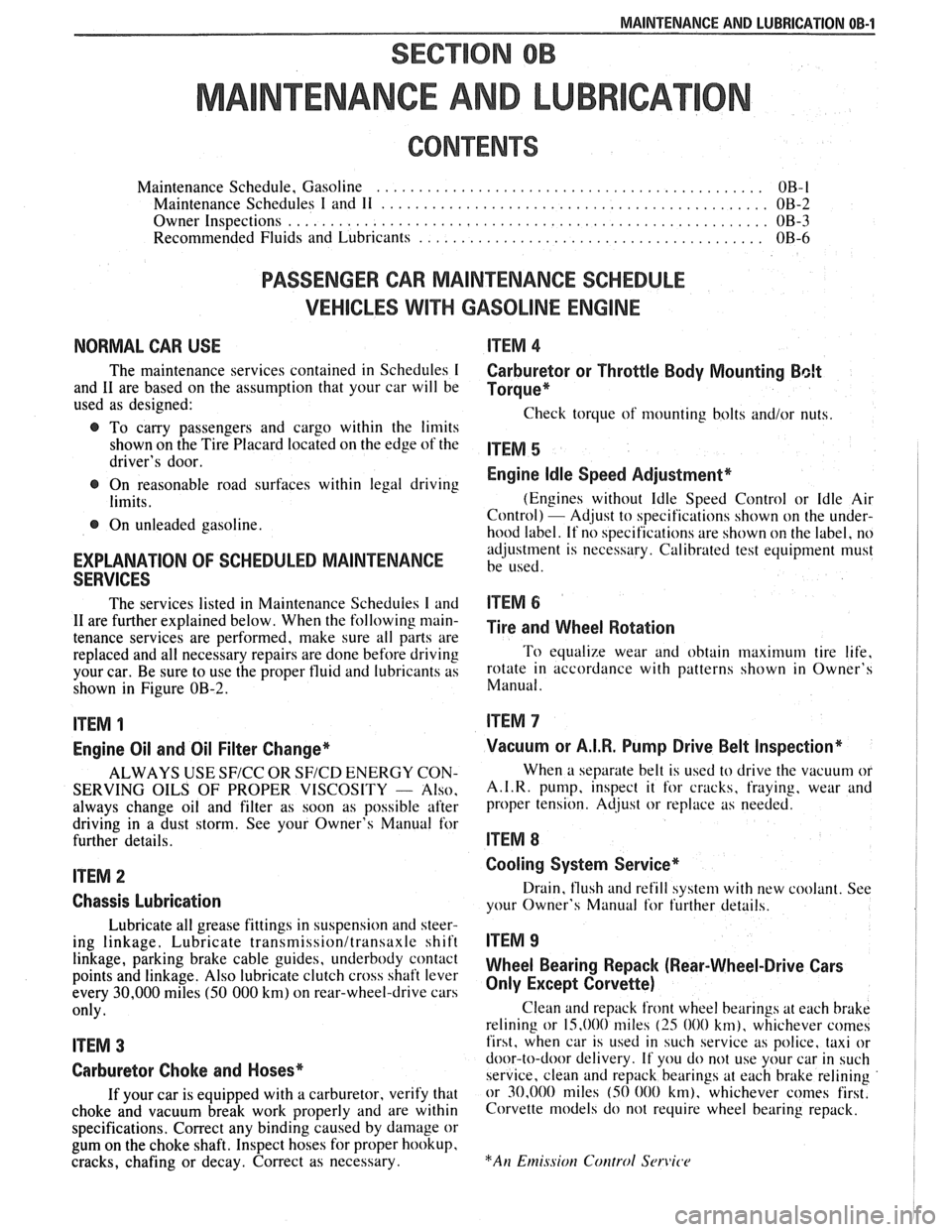
SECTION OB
NTENANCE AND LUBR
CONTENTS
Maintenance Schedule, Gasoline .............................................. OB-l
Maintenance Schedules I and 11 .............................................. OB-2
Owner Inspections
......................................................... OB-3
Recommended Fluids and Lubricants ......................................... OB-6
PASSENGER CAR MAINTENANCE SCHEDULE
VEHICLES
WITH GASOLINE ENGINE
NORMAL CAR USE ITEM 4
The maintenance services contained in Schedules I Carburetor or Throttle Body Mounting Bolt
and 11 are based on the assumption that your car will be Torque* used as designed:
Check torque of mounting bolts and/or nuts. @ To carry passengers and cargo within the limits
shown on the Tire Placard located on the edge of the ITEM 5 driver's door.
@ On reasonable road surfaces within legal driving Engine Idle Speed Adjustment*
limits. (Engines
without Idle Speed Control or Idle Air
Control) - Adjust to specifications shown on the under- @ On unleaded gasoline.
hood label. If no specifications are shown on the label, no
adjustment is necessary. Calibrated test equipment must
EXPLANATION OF SCHEDULED MAINTENANCE be used. SERVICES
The services listed in Maintenance Scheduies I and ITEM 6
11 are further explained below. When the following main- ~i~~ and wheel aotation tenance services are performed, make sure all parts are
replaced and all necessary repairs are done before driving To equalize wear and obtain maximum tire life,
your car. Be sure to use the proper fluid and lubricants as rotate in accordance with patterns shown in Owner's
shown in Figure OB-2. Manual.
ITEM 1
Engine Oil and Oil Filter Change*
ALWAYS USE SFICC OR SF/CD ENERGY CON-
SERVING OILS OF PROPER VISCOSITY
- Also.
always change oil and filter as soon as possible after
driving in a dust storm. See your Owner's Manual for
further details.
ITEM 2
Chassis Lubrication
Lubricate all grease fittings in suspension and steer-
ing linkage. Lubricate
transmissionltransaxle shift
linkage, parking brake cable guides, underbody contact
points and linkage. Also lubricate clutch cross shaft lever
every
30,000 miles (50 000 km) on rear-wheel-drive cars
only.
ITEM 3
Carburetor Choke and Hoses*
If your car is equipped with a carburetor, verify that
choke and vacuum break work properly and are within
specifications. Correct any binding caused by damage or
gum on the choke shaft. Inspect hoses for proper hookup,
cracks, chafing or decay. Correct as necessary.
Vacuum or A.I.R. Pump Drive Belt Inspection*
When a separate belt is used to drive the vacuum or
A.I.R.
pump, inspect it for cracks, fraying, wear and
proper tension. Adjust or replace as needed.
ITEM 8
Cooling System Service*
Drain, flush and refill system with new coolant. See
your Owner's Manual
for further details.
ITEM 9
Wheel Bearing Repack (Rear-Wheel-Drive Cars
Only Except Corvette)
Clean and repack front wheel bearings at each brake
relining or 15,000 miles
(25 000 km), whichever comes
first, when car is used in such service as police, taxi or
door-to-door delivery. If you do not use your car in such
service, clean and repack bearings at each brake relining
or 30,000 miles
(50 000 km), whichever comes first.
Corvette models do not require wheel bearing repack.
Page 21 of 1825
OB-4 MAINTENANCE AND LUBRICATION
Tire and wheel operation - Be alert to a vibra-
tion of the steering wheel or seat at normal highway
speeds. This may mean a wheel balance is needed. Also, a
pull right or left on a straight, level road may show the
need for
a tire pressure adjustment or wheel alignment.
Steering system operation - Be alert to
changes in steering action. An inspection is needed when
the steering wheel is harder to turn or has too much free
play or if unusual sounds are noted when turning or
parking.
Headlight aim operation - Take note of light
pattern occasionally. If beam aim doesn't look right,
headlights should be adjusted.
AT EACH FUEL FILL
Engine oil level check - Check engine oil level
and add if necessary. See your Owner's
Manual for further
details.
NOTICE: A large loss in this system may indicate a
problem. Have it inspected and repaired at once.
Engine coolant level and condition - Check
engine coolant level in coolant reservoir tank and add if
necessary. Replace if dirty or rusty. See your Owner's
Manual for further details.
NOTICE: A large loss in this system may indicate a
problem. Have it inspected and repaired at once.
Windshield washer fluid level check -- Check
washer fluid level in container and add if necessary.
Hood latch operation - When opening hood on
cars equipped with hoods that open from the front, note
the operation of secondary latch. It should keep hood from
opening all the way when primary latch is released. Make
sure that hood closes firmly.
AT LEAST MONTI-ILY
Tire and wheel inspection and pressure
check--
Check tires for abnormal wear or damage. Also,
check for damaged wheels. Keep pressures as shown on
Tire Placard on the driver's door (include spare unless it is
a stowaway). Pressure should b\: checked when tires are
"cold". See "Tires" in Owner's Manual for further
infomation.
Light operation check - Check operation of
license plate light, side-marker lights, headlights includ-
ing high beams, parking lights, taillights, brake lights.
turn signals, backup lights, instrument panel and interior
lights and hazard warning flashers.
Fluid leak check - After the car has been parked
for a while, inspect the surface beneath the car for water,
oil, fuel or other fluids. Water dripping from the air
conditioning system after use is normal. If you notice fuel
leaks or fumes, the cause should be found and corrected at
once.
AT LEAST TWICE A YEAR (FOR EXAMPLE,
EVERY SPRING AND FALL)
Power steering pump fluid level check --
Check power steering pump fluid level in accordance with
Owner's Manual instructions and keep at proper level.
NOTICE: A large loss in this system may indicate a
problem. Have it inspected and repaired at once.
Brake master cylinder reservoir fluid level
check ---- Check fluid and keep at proper level. Note: It is
normal for the brake fluid level to go down slightly as the
brake pads wear
- so be sure to keep reservoir filled.
NOTICE: A large loss in this system may indicate a
problem. Have
it inspected and repaired at once.
Clutch system service --- manual transmis-
sionltransaxle --- For cars equipped with hydraulic
clutch system, check the reservoir fluid level and add fluid
as required. All others, check clutch pedal free travel and
adjust as necessary. See your Owner's Manual for further
details.
~
NOTICE: A large loss in this system may indicate a
problem. Have it inspected and repaired at once.
Weatherstrip Lubrication - Clean surface and
then apply a thin film of silicone grease with a clean cloth.
EACH TIME OIL IS CHANGED
Automatic and manual transmissionltrans-
axle fluid level check - Check transmission/transaxle
fluid level and add as required. (Corvette only) if equipped
with manual transmission
- check fluid in the overdrive
unit and add as required.
NOTICE: A large loss in this system may indicate a
problem. Have
it inspected and repaired at once.
Brake systems inspection - For convenience,
the following should be done when wheels are removed
for rotation: Inspect lines and hoses for proper hookup,
binding, leaks, cracks, chafing, etc. Inspect disc brake
pads for wear and rotors for surface condition. Also in-
spect drum brake linings for wear and cracks. Inspect
other brake parts, including drums, wheel cylinders, park-
ing brake, etc. at the same time. Check parking brake
adjustment.
INSPECT BRAKES MORE OFTEN IF DRIVING
HABITS OR CONDITIONS RESULT IN FREQUENT
BRAKING.
Steering, suspension and front drive axle
boot and seal inspection
- Inspect front and rear
suspension and steering system for damaged, loose or
missing parts, signs of wear or lack of lubrication. Inspect
power steering lines and hoses for proper hookup, bind-
ing, leaks, cracks, chafing, etc. (On cars equipped with
manual steering gear, check for seal leakage.) On
front-
wheel-drive cars, clean then inspect drive axle boot seals
for damage, tears or leakage. Replace seals if necessary.
Exhaust system inspection - Inspect complete
system. Inspect body near the exhaust system. Look for
broken, damaged, missing or out-of-position parts as well
as open seams, holes, loose connections or other condi-
tions which could cause a heat buildup in the tloor pan or
could let exhaust fumes seep into the trunk or passenger
compartment.
Page 23 of 1825
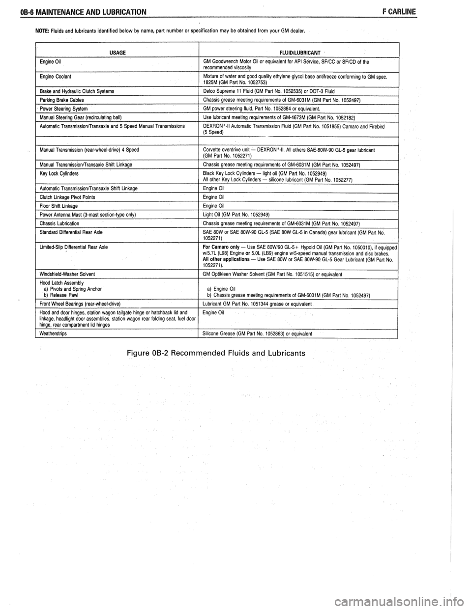
NOTE: Fluids and lubricants identified below by name, part number or specification may be obtained from your GM dealer.
Figure 00-2 Recommended Fluids and Lubricants
USAGE
Engine
Oil
Engine Coolant
Brake and
Hydraul~c Clutch Systems
Parking Brake Cables
Power Steering System
Manual
Steerlng Gear (reclrculat~ng ball)
Automatic
Transrn~ssionRransaxle and 5 Speed Manual Transm~ss~ons
Manual Transm~ssion (rear-wheel-drive) 4 Speed
Manual
Transm~ss~onRransaxle Shin Linkage
Key Lock Cylinders
Automatic Transmlss~onfrransaxle Shlft Llnkage
Clutch Llnkage Plvot Po~nts
Floor Sh~n L~nkage
Power Antenna Mast (3-mast sect~on-type only)
Chass~s Lubr~cation
Standard D~fferent~al Rear Axle
L~m~ted-Sl~p D~flerent~al Rear Axle
W~ndsh~eld.Washer Solvent
Hood Latch Assembly
a)
Plvots and Sprlng Anchor
b) Release Pawl
Front Wheel Bearings
(rearqwheel-drive)
Hood and door hlnges, statlon wagon tailgate hlnge or hatchback Ild and Ilnkage, headl~ght door assembl~es, statlon wagon rear foldrng seat, fuel door hlnge, rear compartment Ihd hlnges
Weatherstr~ps
FLUlDlLUBRlCANT
GM Goodwrench Motor 011 or equivalent for API Se~lce, SFICC or SFICD of the
recommended v~scos~ty
M~xture of water and good qual~ty ethylene glycol base antllreeze conforming to GM spec 1825M (GM Part No 1052753)
Delco Supreme 11
Fluld (GM Part No 1052535) or DOT-3 Fluld
Chass~s grease meetlng requirements of GM-6031M (GM Part No 1052497)
GM power
steerlng flu~d, Part No 1052884 or equivalent
Use lubricant meetlng requirements of GM-4673M (GM Part No 1052182)
DEXR0N'-II Automat~c Transm~ss~on Flu~d (GM Part No 1051855) Camaro and Flreblrd (5 Speed)
Corvette overdr~ve unlt - DEXRON a.II All others SAE-80W-90 GL-5 gear lubr~cant (GM Part No 1052271)
Chass~s grease meetlng requirements of GM-6031M (GM Part No 1052497)
Black Key Lock
Cyl~nders - light oil (GM Par1 No. 1052949)
All other Key Lock Cyl~nders - sllicone lubrlcant (GM Part No 1052277)
Eng~ne 011
Eng~ne 011
Eng~ne 011
Llght 011 (GM Part No 1052949)
Chass~s grease meetlng requirements of GM-6031M (GM Part No 1052497)
SAE
80W or SAE 80W-90 GL-5 (SAE 80W GL-5 In Canada) gear lubricant (GM Part No
1052271)
For Camaro only
- Use SAE BOW190 GL-5+ Hypold 011 (GM Part No 1050010), 11 equ~pped wl5 7L (L98) Englne or 5 OL (LB9) engine wmpeed manual transm~ss~on and disc brakes
All other applications - Use SAE 80W or SAE 80W-90 GL-5 Gear Lubr~cant (GM Part No
1052271)
GM
Opt~kleen Washer Solvent (GM Part No 1051515) or equ~valent
a) Eng~ne 011 b) Chass~s grease meet~ng requirements of GM.6031M (GM Part No 1052497)
Lubricant GM Part No 1051344 grease or equivalent
Eng~ne 011
S~l~cone Grease (GM Part No 1052863) or equivalent
Page 116 of 1825
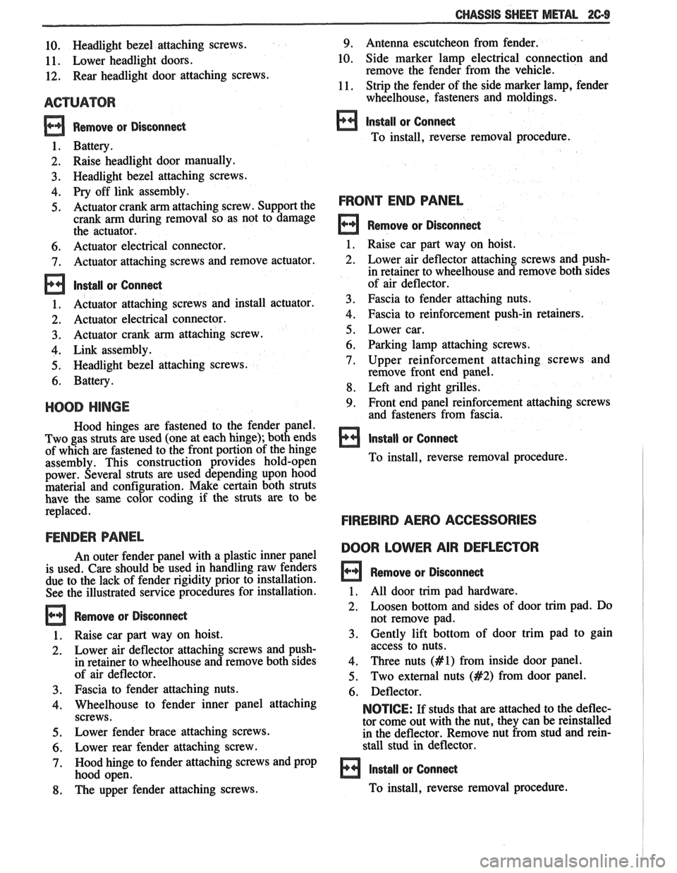
10. Headlight bezel attaching screws.
11. Lower headlight doors.
12. Rear headlight door attaching screws.
ACTUATOR
Remove or Disconnect
1. Battery.
2. Raise headlight door manually.
3. Headlight bezel attaching screws.
4. Pry off link assembly.
5. Actuator crank arm attaching screw. Support the
crank
arm during removal so as not to damage
the actuator.
6. Actuator electrical connector.
7. Actuator attaching screws and remove actuator.
Install or Connect
1, Actuator attaching screws and install actuator.
2, Actuator electrical connector.
3. Actuator crank arm attaching screw.
4. Link assembly.
5. Headlight bezel attaching screws.
6. Battery.
HOOD HINGE
Hood hinges are fastened to the fender panel.
Two gas struts are used (one at each hinge); both ends
of which are fastened to the front portion of the hinge
assembly. This construction provides hold-open
power. Several struts are used depending upon hood
material and configuration. Make certain both struts
have the same color coding if the struts are to be
replaced.
FENDER PANEL
An outer fender panel with a plastic inner panel
is used. Care should be used in handling raw fenders
due to the lack of fender rigidity prior to installation.
See the illustrated service procedures for installation.
Remove or Disconnect
1. Raise car part way on hoist.
2. Lower air deflector attaching screws and push-
in retainer to wheelhouse and remove both sides
of air deflector.
3. Fascia to fender attaching nuts.
4. Wheelhouse to fender inner panel attaching
screws.
5. Lower fender brace attaching screws.
6. Lower rear fender attaching screw.
7. Hood hinge to fender attaching screws and prop
hood open.
-
8. The upper fender attaching screws.
CHASSIS SHEET METAL 2C-9
9. Antenna escutcheon from fender.
10. Side marker lamp electrical connection and
remove the fender from the vehicle.
11. Strip the fender of the side marker lamp, fender
wheelhouse, fasteners and moldings.
install or Conned
To install, reverse removal procedure.
FRONT END PANEL
Remove or Disconnect
1. Raise car part way on hoist.
2. Lower air deflector attaching screws and push-
in retainer to wheelhouse and remove both sides
of air deflector.
3. Fascia to fender attaching nuts.
4. Fascia to reinforcement push-in retainers.
5. Lower car.
6. Parking lamp attaching screws.
7. Upper reinforcement attaching screws and
remove front end panel.
8. Left and right grilles.
9. Front end panel reinforcement attaching screws
and fasteners from fascia.
Install or Conned
To install, reverse removal procedure.
FIREBIRD AERO ACCESSORIES
BOOR LOWER AIR
DEFLECmR
Remove or Disconnect
1. All door trim pad hardware.
2. Loosen bottom and sides of door trim pad. Do
not remove pad.
3. Gently lift bottom of door trim pad to gain
access to nuts.
4. Three nuts (Acl) from inside door panel.
5. Two external nuts (#2) from door panel.
6. Deflector.
NOTICE: If studs that are attached to the deflec-
tor come out with the nut, they can be reinstalled
in the deflector. Remove nut from stud and rein-
stall stud in deflector.
Install or Conned
To install, reverse removal procedure.
Page 117 of 1825
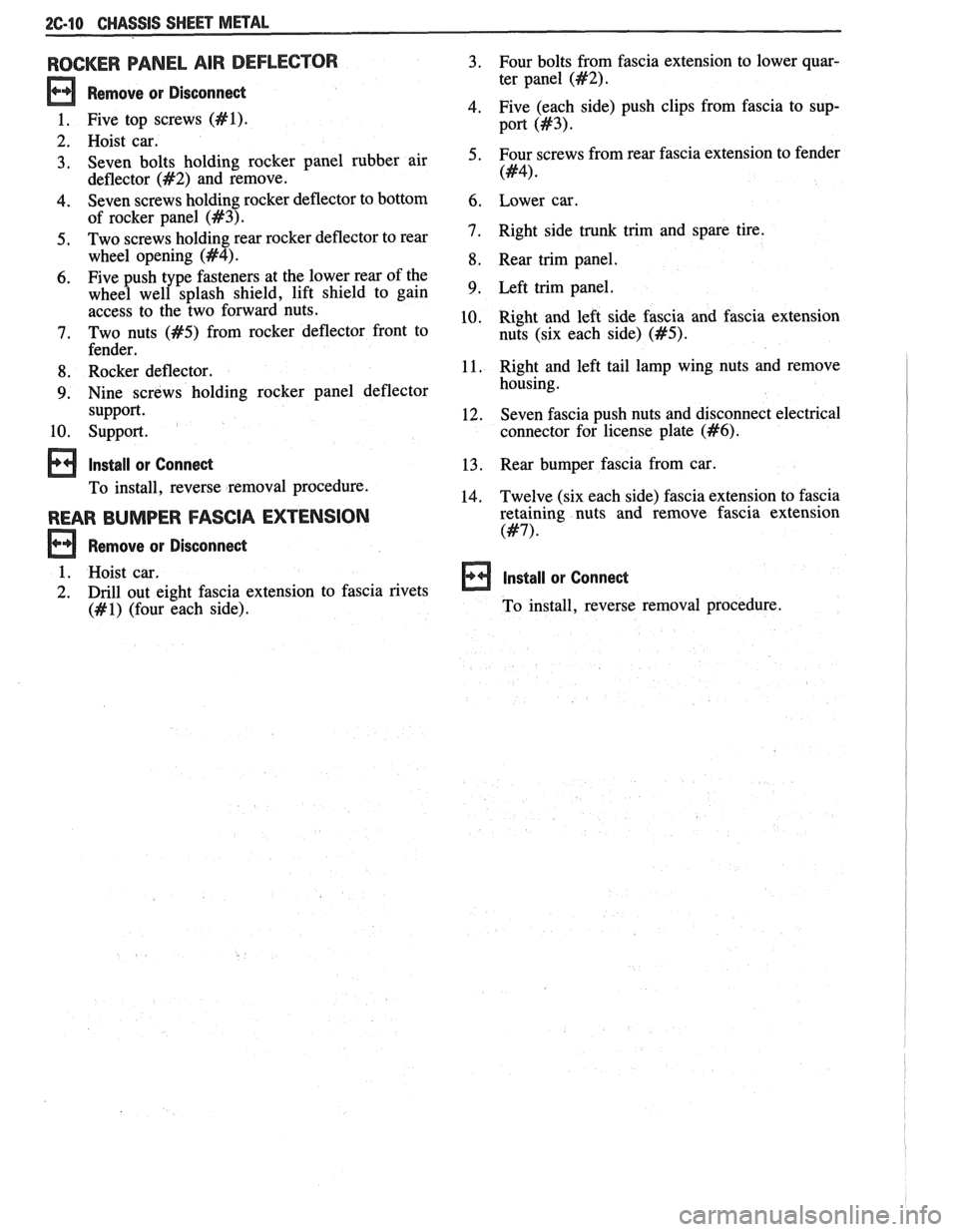
2C-10 CHASSIS SHEET METAL
ROCKER PANEL AIR DEFLECTOR
Remove or Disconnect
1. Five top screws (#I).
2. Hoist car.
3. Seven bolts holding rocker panel rubber
air
deflector
(#2) and remove.
4. Seven screws holding rocker deflector to bottom
of rocker panel
(#3).
5. Two screws holding rear rocker deflector to rear
wheel opening
(#4).
6. Five
push type fasteners at the lower rear of the
wheel well splash shield, lift shield to gain
access to the two forward nuts.
7. Two nuts (#5) from rocker deflector front to
fender.
8. Rocker deflector.
9. Nine screws holding rocker panel deflector
support.
10. Support.
Install or Connect
To install, reverse removal procedure.
REAR BUMPER FASCIA EXTENSION
Remove or Disconnect
1. Hoist car,
2. Drill out
eight fascia extension to fascia rivets
(#I) (four each side). Four
bolts from fascia extension to lower quar-
ter panel
(#2).
Five (each side) push clips from fascia to sup-
port
(443).
Four screws from rear fascia extension to fender
(#4).
Lower car.
Right side trunk trim and spare tire.
Rear trim panel.
Left trim panel.
Right and left side fascia and fascia extension
nuts (six each side)
(#5).
Right and left tail lamp wing nuts and remove
housing.
Seven fascia push nuts and disconnect electrical
connector for license plate
(#6).
Rear bumper fascia from car.
Twelve (six each side) fascia extension to fascia
retaining nuts and remove fascia extension
(#7).
Install or Connect
To install, reverse removal procedure.