1988 PONTIAC FIERO driver seat adjustment
[x] Cancel search: driver seat adjustmentPage 21 of 1825
OB-4 MAINTENANCE AND LUBRICATION
Tire and wheel operation - Be alert to a vibra-
tion of the steering wheel or seat at normal highway
speeds. This may mean a wheel balance is needed. Also, a
pull right or left on a straight, level road may show the
need for
a tire pressure adjustment or wheel alignment.
Steering system operation - Be alert to
changes in steering action. An inspection is needed when
the steering wheel is harder to turn or has too much free
play or if unusual sounds are noted when turning or
parking.
Headlight aim operation - Take note of light
pattern occasionally. If beam aim doesn't look right,
headlights should be adjusted.
AT EACH FUEL FILL
Engine oil level check - Check engine oil level
and add if necessary. See your Owner's
Manual for further
details.
NOTICE: A large loss in this system may indicate a
problem. Have it inspected and repaired at once.
Engine coolant level and condition - Check
engine coolant level in coolant reservoir tank and add if
necessary. Replace if dirty or rusty. See your Owner's
Manual for further details.
NOTICE: A large loss in this system may indicate a
problem. Have it inspected and repaired at once.
Windshield washer fluid level check -- Check
washer fluid level in container and add if necessary.
Hood latch operation - When opening hood on
cars equipped with hoods that open from the front, note
the operation of secondary latch. It should keep hood from
opening all the way when primary latch is released. Make
sure that hood closes firmly.
AT LEAST MONTI-ILY
Tire and wheel inspection and pressure
check--
Check tires for abnormal wear or damage. Also,
check for damaged wheels. Keep pressures as shown on
Tire Placard on the driver's door (include spare unless it is
a stowaway). Pressure should b\: checked when tires are
"cold". See "Tires" in Owner's Manual for further
infomation.
Light operation check - Check operation of
license plate light, side-marker lights, headlights includ-
ing high beams, parking lights, taillights, brake lights.
turn signals, backup lights, instrument panel and interior
lights and hazard warning flashers.
Fluid leak check - After the car has been parked
for a while, inspect the surface beneath the car for water,
oil, fuel or other fluids. Water dripping from the air
conditioning system after use is normal. If you notice fuel
leaks or fumes, the cause should be found and corrected at
once.
AT LEAST TWICE A YEAR (FOR EXAMPLE,
EVERY SPRING AND FALL)
Power steering pump fluid level check --
Check power steering pump fluid level in accordance with
Owner's Manual instructions and keep at proper level.
NOTICE: A large loss in this system may indicate a
problem. Have it inspected and repaired at once.
Brake master cylinder reservoir fluid level
check ---- Check fluid and keep at proper level. Note: It is
normal for the brake fluid level to go down slightly as the
brake pads wear
- so be sure to keep reservoir filled.
NOTICE: A large loss in this system may indicate a
problem. Have
it inspected and repaired at once.
Clutch system service --- manual transmis-
sionltransaxle --- For cars equipped with hydraulic
clutch system, check the reservoir fluid level and add fluid
as required. All others, check clutch pedal free travel and
adjust as necessary. See your Owner's Manual for further
details.
~
NOTICE: A large loss in this system may indicate a
problem. Have it inspected and repaired at once.
Weatherstrip Lubrication - Clean surface and
then apply a thin film of silicone grease with a clean cloth.
EACH TIME OIL IS CHANGED
Automatic and manual transmissionltrans-
axle fluid level check - Check transmission/transaxle
fluid level and add as required. (Corvette only) if equipped
with manual transmission
- check fluid in the overdrive
unit and add as required.
NOTICE: A large loss in this system may indicate a
problem. Have
it inspected and repaired at once.
Brake systems inspection - For convenience,
the following should be done when wheels are removed
for rotation: Inspect lines and hoses for proper hookup,
binding, leaks, cracks, chafing, etc. Inspect disc brake
pads for wear and rotors for surface condition. Also in-
spect drum brake linings for wear and cracks. Inspect
other brake parts, including drums, wheel cylinders, park-
ing brake, etc. at the same time. Check parking brake
adjustment.
INSPECT BRAKES MORE OFTEN IF DRIVING
HABITS OR CONDITIONS RESULT IN FREQUENT
BRAKING.
Steering, suspension and front drive axle
boot and seal inspection
- Inspect front and rear
suspension and steering system for damaged, loose or
missing parts, signs of wear or lack of lubrication. Inspect
power steering lines and hoses for proper hookup, bind-
ing, leaks, cracks, chafing, etc. (On cars equipped with
manual steering gear, check for seal leakage.) On
front-
wheel-drive cars, clean then inspect drive axle boot seals
for damage, tears or leakage. Replace seals if necessary.
Exhaust system inspection - Inspect complete
system. Inspect body near the exhaust system. Look for
broken, damaged, missing or out-of-position parts as well
as open seams, holes, loose connections or other condi-
tions which could cause a heat buildup in the tloor pan or
could let exhaust fumes seep into the trunk or passenger
compartment.
Page 139 of 1825
3-14 STEERING, SUSPENSION, TIRES AND WHEELS DIAGNOSIS
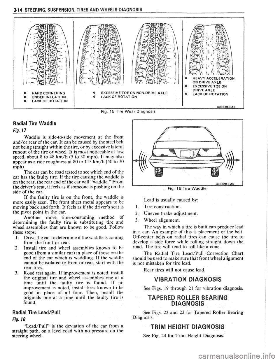
@ HARD CORNERING O UNDER INFLATION LACK OF ROTATION
@ HEAVY ACCELERATION ON DRIVE AXLE EXCESSIVE TOE ON DRIVE AXLE EXCESSIVE TOE ON NON-DRIVE AXLE @ LACK OF ROTATION O LACK. OF ROTAT ION
Fig. 15 Tire Wear Diagnosis
Radial Tire Waddle
Fig. 17
Waddle is side-to-side movement at the front
and/or rear of the car. It can be caused by the steel belt
not being straight within the tire, or by excessive lateral
runout of the tire or wheel. It ig most noticeable at low
speed, about 8 to 48
km/h (5 to 30 mph). It may also
appear as a ride roughness at 80 to 113
km/h (50 to 70
mph). The car can be road tested to see which end of the
car has the faulty tire. If the tire causing the waddle is
on the rear, the rear end of the car will "waddle." From
the driver's seat, it feels as if someone is pushing on the
side of the car.
If the faulty tire is on the front, the waddle is
more easily seen. The front sheet metal appears to be
moving back and forth. It feels as if the driver's seat is
the pivot point in the car.
Another more time-consuming method of
determining the faulty tire is substituting tire and
wheel assemblies that are known to be good. Follow
these steps:
1. Drive the car to determine if the waddle is coming
from the front or rear.
2. Install tire and wheel assemblies known to be
good (from a similar car) in place of those on the
end of the car which is waddling. If the waddle
cannot be isolated to front or rear, start with the
rear tires.
3. Road test again. If improvement is noted, install
the original tire and wheel assemblies one at a
time until the faulty tire is found. If no
improvement is noted, install tires known to be
good in place of all four. Then, install the
originals one at a time until the faulty tire is
found.
Radial Tire Lead/Pull
Fig. 18
"Lead/Pull" is the deviation of the car from a
straight path, on a level road with no pressure
on the
steering wheel.
L Fig. 16 Tire Waddle
Lead is usually caused by:
1. Tire construction.
2. Uneven brake adjustment.
3. Wheel alignment.
The way in which a tire is built can produce lead
in a car. An example of this is placement of the belt.
Off-center belts on radial tires can cause the tire to
develop a side force while rolling straight down the
road. The tire will tend to roll like a cone.
The Radial Tire
Lead/Pull Correction Chart
should be used to make sure that front wheel alignment
is not mistaken for tire lead.
Rear tires will not cause lead.
VIBRATION DIAGNOSIS
See Figs. 19 through 21 for vibration diagnosis.
TAPERED ROLLER BEARING
DlAGNOSlS
See Figs. 22 and 23 for Tapered Roller Bearing
Diagnosis.
See Fig. 24 for Trim Height Diagnosis.
Page 389 of 1825
QA3-10 V-8 ENGINE
lnstallation
1. Install valve stem seal over valve stem and seat
against head.
2. Set
the valve spring and damper, oil shedder and
valve cap in place. Compress the spring with Tool
J-5892 and install oil seal in the lower groove of
the stem, making sure the seal is flat and not
twisted. A light coat of oil on the seal will help
prevent twisting.
3. Install
the valve locks and release the compressor
tool making sure the locks seat properly in the
upper groove of the valve stem. Grease may be
used to hold the locks in place while releasing the
compressor tool.
4. Using tool J-23994, apply vacuum to the valve
cap to make sure no air leaks past the seal.
5. Install spark plug and torque to 22 lb. ft.
(30N.m).
6. Install and adjust valve mechanism as previously
outlined.
VALVE LIFTERS
Hydraulic valve lifters very seldom require
attention. The lifters are extremely simple in design,
readjustments are not necessary, and servicing of the
lifters requires only that care and cleanliness be
exercised in the handling of parts.
Valve Lifter Diagnosis
1.
Momentarily Noisy When Car is Started:
This condition is normal. Oil drains from the
lifters which are holding the valves open when the
engine is not running. It will take a few seconds
for the lifter to fill after the engine is started.
2. Intermittently Noisy On Idle Only. Disappearing
When Engine Speed is Increased:
Intermittent clicking may be an indication of a
pitted check valve ball, or it may be caused by
dirt.
Correction: Clean the lifter and inspect. If check
valve ball is defective, replace lifter.
3. Noisy At Slow Idle Or With Hot Oil, Quiet With
Cold Oil Or As Engine Speed Is Increased:
High leak down rate. Replace suspect lifter.
4. Noisy At High Car Speeds And Quiet At Low
Speeds:
a. High oil level
- Oil level above the "Full"
mark allows crankshaft counterweights to
churn the oil into foam. When foam is
pumped into the lifters, they will become
noisy since a solid column of oil is required
for proper operation. Correction: Drain oil
inti1 proper level is obtained.
b. Low oil level - Oil level below the "Add"
mark allows the pump to pump air at high
speeds which results in noisy lifters.
Correction: Fill until proper oil level is
obtained.
c. Oil pan bent on bottom or pump screen
cocked or loose, replace or repair as
necessary. 5.
Noisy At Idle Becoming Louder As Engine Speed
Is Increased To 1500 rpm:
This noise is not connected with lifter
malfunction. It becomes most noticeable in the
car at 10 to 15 mph "1" (Low) range, or 30 to
35
mph "DM (Drive) range and is best described as
a
hashy sound. At slow idle, it may be entirely
gone or appear as a light ticking noise in one or
more valves. It is caused by one or more of the
following:
a. Badly worn or scuffed valve tip and rocker
arm pad.
b. Excessive valve stem to guide clearance.
c. Excessive valve seat
runout.
d. Off square valve spring.
e. Excessive valve face
runout.
f. Valve spring damper clicking on rotator.
Removal
1.
Remove intake manifold as previously outlined.
2. Remove valve mechanism as previously outlined.
3. Remove valve lifter retainer.
4. Remvoe valve lifter restrictor.
5. Remove valve lifters (Fig.
6A3-7). Place valve
lifters in a rack so that they may be reinstalled in
the same location.
Installation
1.
Coat roller of valve lifters with "Molykote" or its
equivalent and install valve lifters.
2. Install valve lifter restrictor.
3. Install valve lifter retainer.
4. Install intake manifold as previously outlined.
5. Install and adjust valve mechanism as outlined.
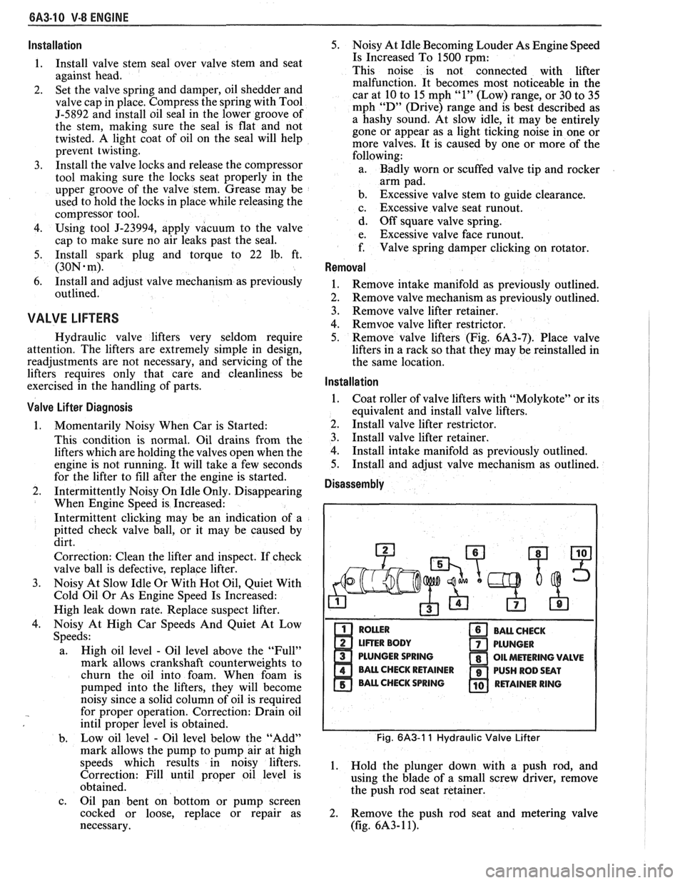
Disassembly
PLUNGER SPRING
Fig. 6A3-1 1 Hydraulic Valve Lifter
1. Hold the plunger down with a push rod, and
using the blade of a small screw driver, remove
the push rod seat retainer.
2. Remove the push rod seat and metering valve
(fig.
6A3- 1 1).
Page 1609 of 1825
Adjust 2 . Filler panel 3 . Electrical connector
1 . Increase Current - Turn adjusting screw 4 . ~~l~/~~~~~
clockwise 5 . Horn
2 . Decrease Current . Turn adjusting screw
counterclockwise
Install or Connect
3 . Current adjustments should be made 1/4 turn
(90") at a time
Horn Assembly
Remove or Disconnect
1 . Six screws from filler panel behind front fascia on
driver's side 1
. Horn
2 . Bolt/screw
3 . Electrical connector
4
. Filler panel
5 . Six screws
Horn Relay
The horn relay is in the convenience center.
behind the instrument panel to the right of the steering
column
. To remove the relay. pull it straight out .
REPLACEMENT LIGHT BULBS
For exterior light replacement procedures. see the rest of this
section
. For interior light replacement procedures. see Section $A
and Section 8C .
EXTERIOR LIGHTS Trade No . ...................................................................................................................... Back-up Lights 1 156
Center
High-Mounted Stoplight ............................................................................................. 577
Front Barking/Turn Signal Eights ..................................................................................... 2057
Fog Lights
............................................................................................................................... H-3
Headlights ....................................................................................................................... H6054 ................................................................................................................ License Plate Lights 194
.................................................................................... Rear Tail/Stop/Turn Signal Lights 2057
Sidemarker Lights (Front and Rear) ...................................................................................... 194 ..................................................................................................................... Underhood Light 211
BNTERBOR LIGHTS Trade No .
......................................................................................... Air Conditioner/Heater Controls 194 .................................................................................................................. Ashtray & Lighter 194 .............................................................................................................. Cargo Compartment 561
................................................................................................ Cluster & Speedometer (Tach) 194 ..................................................................................................................... Console Ashtray 194 ............................................................................................................. Console Compartment 194
Courtesy Lights
..................................................................................................................... 194 ......................................................................................................................... Dome Light 561
Gear Selector Indicator
............................................................................................................ 74 .......................................................................................... Headlight High-Beam Indicator 194
Indicator Lights
..................................................................................................... Brake System Warning 194
With Gages
........................................................................................................................ 74
............................................................... Charging System Warning (except Rally Gages) 194 .................................................................................................................... Choke Warning
194
With Gages
........................................................................................................................ 74
...................................................................... Oil Pressure Warning (except Rally Gages) 194 ............................................................................................................ Seat Belt
Reminder 194
With Gages
.................................... ... ................................................................................. 74 ............................................................................................. Service Engine Soon Warning 194
With Gages
..................................................................................................................... 74 ............................................................ Temperature Gage Warning (except Rally Gages) 194
........................................................................................................................ Reading
Light 906 ............................................................................................................ Turn Signal Indicators 194
Page 1677 of 1825
96.4 MISCELLANEOUS ACCESSORIES
DASH AND CONSOLE MOUNTED ACCESSORY
SWITCHES
Installation for various dash and console
mounted accessory switches is shown in Section
8C.
GENERAL DESCRIPIIOM
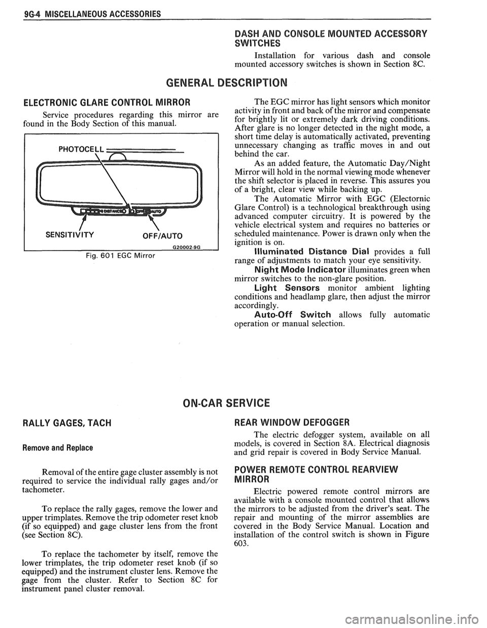
ELECTRONIC GLARE CONTROL MIRROR
Service procedures regarding this mirror are
found in the Body Section of this manual.
Fig. 601 EGC Mirror
The EGC mirror has light sensors which monitor
activity in front and back of the mirror and compensate
for brightly lit or extremely dark driving conditions.
After glare is no longer detected in the night mode, a
short time delay is automatically activated, preventing
unnecessary changing as traffic moves in and out
behind the car.
As an added feature, the Automatic
Day/Night
Mirror will hold in the normal viewing mode whenever
the shift selector is placed in reverse. This assures you
of a bright, clear view while backing up.
The Automatic Mirror with EGC (Electornic
Glare Control) is a technological breakthrough using
advanced computer circuitry. It is powered by the
vehicle electrical system and requires no batteries or
scheduled maintenance. Power is drawn only when the
ignition is on.
Illuminated Distance Dial provides a full
range of adjustments to match your eye sensitivity.
Night Mode Indicator illuminates green when
mirror switches to the non-glare position.
Light Sensors monitor ambient lighting
conditions and
headlamp glare, then adjust the mirror
accordingly.
Auto-Off Switch allows fully automatic
operation or manual selection.
ON-CAR SERVICE
RALLY GAGES, TACH REAR WINDOW DEFOGGER
Remove
and Replace
The electric defogger system, available on all
models, is covered in Section
8A. Electrical diagnosis
and grid repair is covered in Body Service Manual.
Removal of the entire gage cluster assembly is not
POWER RmOTE CONTROL REARVIEW
required to service the individual rally gages and/or MIRROR
tachometer.
Electric powered remote control mirrors are
available with a console mounted control that allows
To replace the rally gages, remove the lower and the
mirrors to be adjusted from the driver's seat. The
upper trimplates. Remove the trip odometer reset knob repair
and mounting of the mirror assemblies are
(if so equipped) and gage cluster lens from the front covered in
the Body Service Manual. Location and
(see Section
8C). installation of the control switch is shown in Figure
603.
To replace the tachometer by itself, remove the
lower trimplates, the trip odometer reset knob (if so
equipped) and the instrument cluster lens. Remove the
gage from the cluster. Refer to Section
8C for
hstrument panel cluster removal.
Page 1784 of 1825
SEATS - F STYLE 9H-1
SEC"IC"0N 9H
SEATS
NOTICE: Lap belt to floor pan and shoulder belt to roof panel or quarter panel fasteners are important
attaching parts in that they could affect the performance of vital parts and systems, and/or could result in major
repair expense. They must be replaced with one of the same part number or with an equivalent part if replacement
becomes necessary. Do not use a replacement part of lesser quality or substitute design. Torque values must be
used as specified during reassembly to assure proper retention of these parts.
CONTENTS
Restraint Systems ........................................... 9H- 1
Lap and Shoulder Belts
............................... 9H-1
Comfort Lock Operational Checks
and Requirements
.................................... 9H- 1
Front Seat Shoulder Belt Retractor
............ 9H-2
Child Seat
...................................................... 9H-2
............................... .................. -.rant Seats .. 9H-5
Mead Restraint
............................................. 9H-5
Reclining
Seatback ................................... 9H-6
Front
Seatback ........................................... 9H-7
Inertia Lock Check
...................................... 9H-7
............................... Manual Recliner Check 9H-7
........................... Seat Torque Specifications 9H-8
Manual Seat
- Diagnosis Chart ................... 9H-8
..................... Power Seat - Diagnosis Chart 9H-9
RESTRAINT SYSTEMS
LAP
AND SHOULDER BELTS
The front seat belts incorporate a 4-to-8 second
fasten seat belt reminder lamp and sound signal
designed to remind the driver if the lap and shoulder
belts are not fastened when the ignition is turned to the
on position. If the driver's seat belt
is buckled, the
alarm will not operate; however, the fasten seat belt
xminder lamp will stay on for a 4-to-8 second period.
,, the driver's seat belt is not buckled, the reminder
lamp and sound signal will automatically shut off after
the 4-to-8 second interval. To diagnose a system
failure, refer to Seat Belt Reminder
Lamp/Alarm
Diagnosis in Section 8A.
The shoulder belt is attached to the front seat lap
belt latch plate and connected to an inertia locking
retractor installed to the roof panel above the right and
left side of the front seat. The shoulder belt remains
unlocked to allow the occupants to move freely while
the vehicle is being operated. When the vehicle
decelerates or changes direction abruptly, the shoulder
belt is locked in position by a pendulum that causes a
locking bar to engage a cog of the retractor mechanism.
The retractor has a comfort lock feature that
allows the occupant to adjust the shoulder belt for
proper fit and comfort. When engaged, the comfort
lock prevents full retraction of the webbing to eliminate
occupant discomfort due to webbing load on the
shoulder. The occupant can readjust the comfort lock
during vehicle operation as described below.
When servicing or replacing lap and shoulder
belts, refer to the following precautionary items: Front
Seat Adjustments
............................... 9H- 10
Manual Seat Control Arm Knob
................ 9H-10
Front Seat Assembly
.................................... 9H- 1 1
Seat Adjuster Assembly ............................. 9H-11
Six-way Seat Adjuster .................................. 9H- 12
Power Seat Switch
........................................ 9H-15
Four-way Manual Seat Adjuster
................. 9H-15
Seatback Lock Striker/Side Bar Stop .......... 9H-15
High Performance AQ9 Seat
(2FS87) ......... 9H-15
................. .................................... Rear Seats ... 9H- 19
........................................ Cushion Assembly 9H- 19
................................ Folding Rear Seatback 9H- 19
........................... Seatback Lock Assembly 9H-20
.................................. Seatback Lock Striker 9H-20
1. Lap and shoulder belts will be serviced as follows:
a. Retractor
portion(s) of
front seat lap and
shoulder belt for outboard passenger and
driver.
b. Buckle portion of front seat lap belt for
outboard passenger and driver.
c. All belts other than those mentioned in
above steps a and b will be serviced in
complete sets.
d. Do not intermix standard and deluxe belts
on front or rear seats.
2. Keep sharp edges and damaging objects away
from belts.
3. Avoid bending or damaging any portion of the
belt buckle or latch plate.
4. Do not bleach or dye belt webbing (clean with a
mild soap solution and water).
5. When installing lap or shoulder belt anchor bolt,
start bolt by hand to assure that bolt is threaded
straight.
NOTICE: See NOTICE on page 9H-1 of this
section.
6. Do not attempt repairs on lap or shoulder belt
retractor mechanisms or lap belt retractor covers.
Replace with new service replacement parts.
Comfort Lock Operational Checks and Requirements
The shoulder belt comfort lock feature must
function as follows:
1. Extend the webbing from the retractor to a
distance approximating buckled position.
Page 1793 of 1825
8'
9H-10 SEATS - F STYLE
4. One adjuster will 1. Vertical drive cable 1. Check vertical drive
not operate vertically. disconnected or damaged. cables, replace if damaged.
2. Vertical gearnut 2. Replace vertical
inoperative. actuator assembly.
5. Both adjusters will 1. Inoperative horizontal 1. See chassis manual
not operate horizon- and/or vertical solenoid Section
8A.
tally and/or verti- in transmission.
cally. 2. Damaged, broken or 2. Replace damaged, broken
inoperable solenoid or inoperable solenoid part
plunger, shaft, dog, dog
with new part.
spring, gear or drive
gear.
6. Vertical chuck or
1. Excessive clearance at
1. Grind down top of verti-
looseness. vertical
gearnut tension cal gearnut shoulder nut
spring. 0.40 to 1.19 mm
(1/64" to
3.64") maximum.
Front Seat Adjustments
Seat Adjustment at Floor Pan Attachment
A small amount of fore and aft or side adjustment
is available at the seat adjuster-to-floor pan attaching
bolts which can be used toward alignment of the seat
assembly or alignment of the seat adjusters with each
other. This adjustment can be used to help correct the
following conditions:
1. Nard or slow operation due to adjusters not being
parallel with each other.
2. Passenger side of manually operated seat must be
moved forward or rearward slightly to engage in
locked position due to one adjuster being forward
or rearward of the other.
3. Seat assembly slightly too far to right or left.
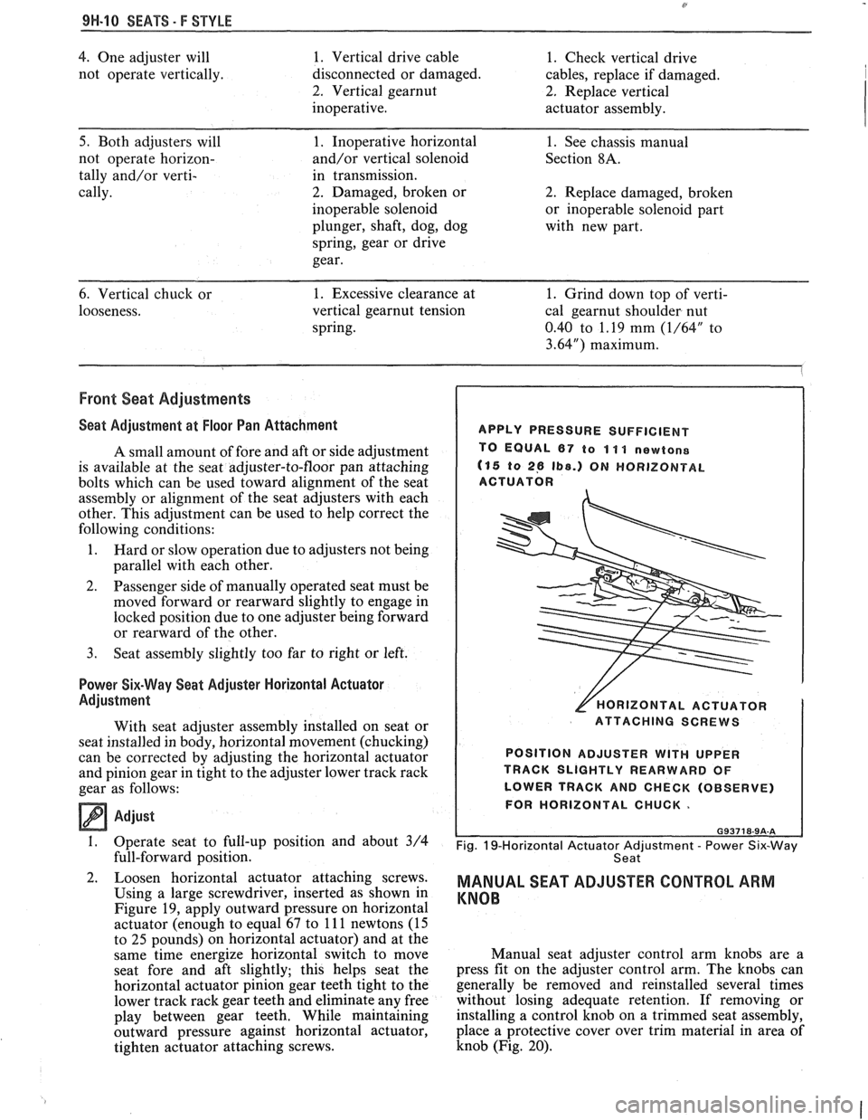
Power Six-Way Seat Adjuster Horizontal Actuator
Adjustment
With seat adjuster assembly installed on seat or
seat installed in body, horizontal movement (chucking)
can be corrected by adjusting the horizontal actuator
and pinion gear in tight to the adjuster lower track rack
gear as follows:
Adjust -
1. Operate seat to full-up position and about 3/4
full-forward position.
Loosen horizontal actuator attaching screws.
Using a large screwdriver, inserted as shown in
Figure
19, apply outward pressure on horizontal
actuator (enough to equal 67 to
11 1 newtons (15
to
25 pounds) on horizontal actuator) and at the
same time energize horizontal switch to move
seat fore and aft slightly; this helps seat the
horizontal actuator pinion gear teeth tight to the
lower track rack gear teeth and eliminate any free
play between gear teeth. While maintaining
outward pressure against horizontal actuator,
tighten actuator attaching screws.
APPLY PRESSURE SUFFICIENT
TO EQUAL
67 to 11 1 newtone
(15 to 26 Ib8.) ON HORIZONTAL
ACTUATOR
[HORIZONTAL ACTUATOR
ATTACHING SCREWS
POSITION ADJUSTER
WITH UPPER
TRACK SLIGHTLY REARWARD OF
LOWER TRACK AND CHECK (OBSERVE)
FOR HORIZONTAL CHUCK.
Fig. 19-Horizontal Actuator Adjustment - Power Six-Way
Seat
MANUAL SEAT ADJUSTER CONTROL ARM
KNOB
Manual seat adjuster control arm knobs are a
press fit on the adjuster control arm. The knobs can
generally be removed and reinstalled several times
without losing adequate retention. If removing or
installing a control knob on a trimmed seat assembly,
place a protective cover over trim material in area of
knob (Fig. 20).