1988 PONTIAC FIERO hood release
[x] Cancel search: hood releasePage 21 of 1825
OB-4 MAINTENANCE AND LUBRICATION
Tire and wheel operation - Be alert to a vibra-
tion of the steering wheel or seat at normal highway
speeds. This may mean a wheel balance is needed. Also, a
pull right or left on a straight, level road may show the
need for
a tire pressure adjustment or wheel alignment.
Steering system operation - Be alert to
changes in steering action. An inspection is needed when
the steering wheel is harder to turn or has too much free
play or if unusual sounds are noted when turning or
parking.
Headlight aim operation - Take note of light
pattern occasionally. If beam aim doesn't look right,
headlights should be adjusted.
AT EACH FUEL FILL
Engine oil level check - Check engine oil level
and add if necessary. See your Owner's
Manual for further
details.
NOTICE: A large loss in this system may indicate a
problem. Have it inspected and repaired at once.
Engine coolant level and condition - Check
engine coolant level in coolant reservoir tank and add if
necessary. Replace if dirty or rusty. See your Owner's
Manual for further details.
NOTICE: A large loss in this system may indicate a
problem. Have it inspected and repaired at once.
Windshield washer fluid level check -- Check
washer fluid level in container and add if necessary.
Hood latch operation - When opening hood on
cars equipped with hoods that open from the front, note
the operation of secondary latch. It should keep hood from
opening all the way when primary latch is released. Make
sure that hood closes firmly.
AT LEAST MONTI-ILY
Tire and wheel inspection and pressure
check--
Check tires for abnormal wear or damage. Also,
check for damaged wheels. Keep pressures as shown on
Tire Placard on the driver's door (include spare unless it is
a stowaway). Pressure should b\: checked when tires are
"cold". See "Tires" in Owner's Manual for further
infomation.
Light operation check - Check operation of
license plate light, side-marker lights, headlights includ-
ing high beams, parking lights, taillights, brake lights.
turn signals, backup lights, instrument panel and interior
lights and hazard warning flashers.
Fluid leak check - After the car has been parked
for a while, inspect the surface beneath the car for water,
oil, fuel or other fluids. Water dripping from the air
conditioning system after use is normal. If you notice fuel
leaks or fumes, the cause should be found and corrected at
once.
AT LEAST TWICE A YEAR (FOR EXAMPLE,
EVERY SPRING AND FALL)
Power steering pump fluid level check --
Check power steering pump fluid level in accordance with
Owner's Manual instructions and keep at proper level.
NOTICE: A large loss in this system may indicate a
problem. Have it inspected and repaired at once.
Brake master cylinder reservoir fluid level
check ---- Check fluid and keep at proper level. Note: It is
normal for the brake fluid level to go down slightly as the
brake pads wear
- so be sure to keep reservoir filled.
NOTICE: A large loss in this system may indicate a
problem. Have
it inspected and repaired at once.
Clutch system service --- manual transmis-
sionltransaxle --- For cars equipped with hydraulic
clutch system, check the reservoir fluid level and add fluid
as required. All others, check clutch pedal free travel and
adjust as necessary. See your Owner's Manual for further
details.
~
NOTICE: A large loss in this system may indicate a
problem. Have it inspected and repaired at once.
Weatherstrip Lubrication - Clean surface and
then apply a thin film of silicone grease with a clean cloth.
EACH TIME OIL IS CHANGED
Automatic and manual transmissionltrans-
axle fluid level check - Check transmission/transaxle
fluid level and add as required. (Corvette only) if equipped
with manual transmission
- check fluid in the overdrive
unit and add as required.
NOTICE: A large loss in this system may indicate a
problem. Have
it inspected and repaired at once.
Brake systems inspection - For convenience,
the following should be done when wheels are removed
for rotation: Inspect lines and hoses for proper hookup,
binding, leaks, cracks, chafing, etc. Inspect disc brake
pads for wear and rotors for surface condition. Also in-
spect drum brake linings for wear and cracks. Inspect
other brake parts, including drums, wheel cylinders, park-
ing brake, etc. at the same time. Check parking brake
adjustment.
INSPECT BRAKES MORE OFTEN IF DRIVING
HABITS OR CONDITIONS RESULT IN FREQUENT
BRAKING.
Steering, suspension and front drive axle
boot and seal inspection
- Inspect front and rear
suspension and steering system for damaged, loose or
missing parts, signs of wear or lack of lubrication. Inspect
power steering lines and hoses for proper hookup, bind-
ing, leaks, cracks, chafing, etc. (On cars equipped with
manual steering gear, check for seal leakage.) On
front-
wheel-drive cars, clean then inspect drive axle boot seals
for damage, tears or leakage. Replace seals if necessary.
Exhaust system inspection - Inspect complete
system. Inspect body near the exhaust system. Look for
broken, damaged, missing or out-of-position parts as well
as open seams, holes, loose connections or other condi-
tions which could cause a heat buildup in the tloor pan or
could let exhaust fumes seep into the trunk or passenger
compartment.
Page 22 of 1825
MAINTENANCE AND LUBRICATION OB-5
Throttle linkage inspection -- Inspect for inter-
ference, binding, damaged or missing parts.
Engine drive belts inspection - Inspect all
belts for cracks, fraying and wear. Adjust or replace as
needed.
Rear axle service (if equipped) - Check gear
lubricant level and add if needed. For cars equipped with a
limited slip rear axle, fluid does not require changing
(except Caprice and Corvette
- change fluid and required
additive at first
7,500 miles (12 500 km). See your
Owner's Manual or "Recommended Fluids
& Lubricants
Chart" in this section.
IF YOU USE YOUR GAR TO PULL A TRAILER,
CHANGE GEAR LUBRICANT EVERY 7,500 MILES
(12 500 KM).
NOTICE: A large loss in this system may indicate a
problem. Have it inspected and repaired at once.
Power antenna - Clean and then lubricate power
antenna mast. The proper lubricant as shown in Figure
OB-2 should be used.
AT LEAST ONCE A YEAR
Lap and shoulder belts condition and opera-
tion
- Inspect belt system, including webbing, buckles,
latch plates, retractors, guide loops and anchors.
Moveable head restraint operation - On cars
with moveable restraints, make sure restraints stay in the
desired position. (See adjustment instructions in your
Owner's Manual.)
Seatback latch and recliner operation on
cars equipped
with recliner seat --- Be sure seat-
backs latch on those cars with folding seats using mechan-
ical latches. Make sure the recliner is holding by pushing
and pulling on the top of the
seatback while it is reclined.
See your Owner's Manual for seat operating information.
Spare tire and jack storage- Be alert to rattles
in rear of car. Make sure the space tire, all jacking equip-
ment, any tire inflator and any covers or doors are securely
stowed at all times. Oil jack ratchet or screw mechanism
after each use.
Key lock service - Lubricate key lock cylinder at
least annually.
Body lubrication service - Lubricate all body
door hinges including the tailgate or hatchback lid (if
equipped). Also lubricate the body hood, fuel door and
rear compartment hinges and latches including interior
glove box and counsel doors, and any folding seat
hardware.
"Fansmissionltransaxle neutral or clutch
starl switch operation
CAUnON: Before pedorming the follow-
ing safety switch check, be sure to have
enough room around the car. Then, firmly
apply both the parking brake (see your
Owner's Manual for procedure) and the
regular brakes. Do not use the accelerator pedal.
If the engine
starls, be ready to turn
off the ignition promptly. Take these pre-
cautions because the car could move
without warning and possibly cause per-
sonal injury or properly damage. On auto-
matic transmissionltransaxle cars, try to
starl the engine in each gear. The starler
should crank only in "Park" or "Neutral."
On manual transmissionltransaxle cars,
place the
shiR lever in "Neutral," push the
clutch halfway and try to starl. The starler
should crank only when the clutch is fully
depressed.
Steering column lock operation
- While
parked, try to turn key to "Lock" in each gear range. The
key should turn to "Lock" only when gear is in "Park" on
automatic or "Reverse" on manual
transmissionltransax-
le. On cars with key release lever, try to turn key toULock"
without depressing the lever. The key should turn to
"Lock" only with the key lever depressed. On all vehicles,
the key should come out only in "Lock."
Parking brake and transmissionltransaxle
"Park" mechanism operation
CAUT1ON:Before checking the holding
ability of the parking brake and automatic
transmissionltransaxle "Park" mecha-
nism, park on a fairly steep hill with
enough room for movement in the down-
hill direction. To reduce the risk of person-
al injury or property damage, be prepared
to apply the regular brakes promptly if the
car begins to move.
To check the parking brake, with the engine running and
transmission/transaxle in "Neutral." slowly remove foot
pressure from the regular brake pedal (until the car is held
by only the parking brake).
To check the automatic transmissionltransaxle "Park"
mechanism holding ability, release all brakes after shift-
ing the transmissionltransaxle to "Park."
ljnderbody flushing - At least every spring,
tlush from the underbody with plain water any corrosive
materials used for ice and snow removal and dust control.
Take care to thoroughly clean any areas where mud and
other debris can collect.
Sediment packed in closed areas
of the vehicle should be loosened before being flushed.
Engine cooling system service - Inspect
coolant and freeze protection. If dirty or rusty, drain, flush
and refill with new coolant. Keep coolant
at the proper
mixture as specified in your Owner's Manual. This pro-
vides proper freeze protection. corrosion inhibitor level
and engine operating temperature. Inspect hoses and re-
place if cracked. swollen or deteriorated. Tighten hose
clamps. Clean outside of radiator and air conditioning
condensor. Wash radiator filler cap and neck.
To help
ensure proper operation. a pressure test of both the cooling
system and cap is also recommended. (See maintenance
schedule charts in Figure
OB-l for the recommended
coolant change interval.)
Page 23 of 1825
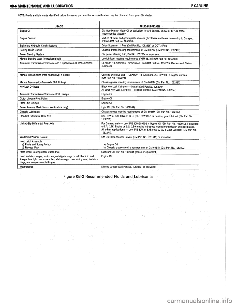
NOTE: Fluids and lubricants identified below by name, part number or specification may be obtained from your GM dealer.
Figure 00-2 Recommended Fluids and Lubricants
USAGE
Engine
Oil
Engine Coolant
Brake and
Hydraul~c Clutch Systems
Parking Brake Cables
Power Steering System
Manual
Steerlng Gear (reclrculat~ng ball)
Automatic
Transrn~ssionRransaxle and 5 Speed Manual Transm~ss~ons
Manual Transm~ssion (rear-wheel-drive) 4 Speed
Manual
Transm~ss~onRransaxle Shin Linkage
Key Lock Cylinders
Automatic Transmlss~onfrransaxle Shlft Llnkage
Clutch Llnkage Plvot Po~nts
Floor Sh~n L~nkage
Power Antenna Mast (3-mast sect~on-type only)
Chass~s Lubr~cation
Standard D~fferent~al Rear Axle
L~m~ted-Sl~p D~flerent~al Rear Axle
W~ndsh~eld.Washer Solvent
Hood Latch Assembly
a)
Plvots and Sprlng Anchor
b) Release Pawl
Front Wheel Bearings
(rearqwheel-drive)
Hood and door hlnges, statlon wagon tailgate hlnge or hatchback Ild and Ilnkage, headl~ght door assembl~es, statlon wagon rear foldrng seat, fuel door hlnge, rear compartment Ihd hlnges
Weatherstr~ps
FLUlDlLUBRlCANT
GM Goodwrench Motor 011 or equivalent for API Se~lce, SFICC or SFICD of the
recommended v~scos~ty
M~xture of water and good qual~ty ethylene glycol base antllreeze conforming to GM spec 1825M (GM Part No 1052753)
Delco Supreme 11
Fluld (GM Part No 1052535) or DOT-3 Fluld
Chass~s grease meetlng requirements of GM-6031M (GM Part No 1052497)
GM power
steerlng flu~d, Part No 1052884 or equivalent
Use lubricant meetlng requirements of GM-4673M (GM Part No 1052182)
DEXR0N'-II Automat~c Transm~ss~on Flu~d (GM Part No 1051855) Camaro and Flreblrd (5 Speed)
Corvette overdr~ve unlt - DEXRON a.II All others SAE-80W-90 GL-5 gear lubr~cant (GM Part No 1052271)
Chass~s grease meetlng requirements of GM-6031M (GM Part No 1052497)
Black Key Lock
Cyl~nders - light oil (GM Par1 No. 1052949)
All other Key Lock Cyl~nders - sllicone lubrlcant (GM Part No 1052277)
Eng~ne 011
Eng~ne 011
Eng~ne 011
Llght 011 (GM Part No 1052949)
Chass~s grease meetlng requirements of GM-6031M (GM Part No 1052497)
SAE
80W or SAE 80W-90 GL-5 (SAE 80W GL-5 In Canada) gear lubricant (GM Part No
1052271)
For Camaro only
- Use SAE BOW190 GL-5+ Hypold 011 (GM Part No 1050010), 11 equ~pped wl5 7L (L98) Englne or 5 OL (LB9) engine wmpeed manual transm~ss~on and disc brakes
All other applications - Use SAE 80W or SAE 80W-90 GL-5 Gear Lubr~cant (GM Part No
1052271)
GM
Opt~kleen Washer Solvent (GM Part No 1051515) or equ~valent
a) Eng~ne 011 b) Chass~s grease meet~ng requirements of GM.6031M (GM Part No 1052497)
Lubricant GM Part No 1051344 grease or equivalent
Eng~ne 011
S~l~cone Grease (GM Part No 1052863) or equivalent
Page 91 of 1825
4 Dl-I 2 R-4 AIR CONDITIONING COMPRESSOR OVERHAUL
MAJOR REPAIR PROCEDURES
Service repair procedures to the
Compressor Shaft Seal,
Pressure Relief Valve
or disassembly
of the Internal Compressor
Cylinder and Shaft Assembly are considered
"MAJOR" SINCE THE REFRIGERATION
SYSTEM MUST BE DISCHARGED,
EVACUATED AND RECHARGED to complete
service and/or because major internal
operating and sealing components of the
compressor are being disassembled and
serviced.
When replacing the shaft seal assembly or
pressure relief valve, even if the compressor remains on
the vehicle during the operation, it will be necessary to
discharge the system of refrigerant (see Section
1B).
Other than clutch repair procedures, the same holds
true for any disassembly of the compressor.
If the compressor shell, front head or cylinder
and shaft assembly are to be serviced or replaced, the
oil in the compressor must be drained, measured and
replaced (see Section
1B) to determine addition of
proper oil quantity to new assembly.
A clean workbench, preferably covered with a
sheet of clean paper, orderliness in the work area and
a place for all parts being removed and replaced is of
great importance, as is the use of the proper, clean
service tools.
NOTICE: Any attempt to use make-shift or
inadequate equipment may result in damage
and/or improper compressor operation.
All parts required for servicing the internal
compressor are protected by a preservation process and
packaged in a manner which will eliminate the
necessity of cleaning, washing or flushing of the parts.
The parts can be used in the internal assembly just as
they are removed from the service package.
Seals and
protective packaging should be left in tact un
ti1 just
prior to installation.
SI-IAFT SEAL
Fig. 35 thru 40
Shaft Seal Design
The shaft seal is a one piece design.
Seal Leak Detection
A shaft seal should not be changed because of an
oil-line on the hood insulator. The Seal is designed to
seep some oil for lubrication purposes. Only change a
Shaft Seal when a leak is detected by evidence of oil
sprayed in large amounts and then only after actual
refrigerant leakage is found by using an approved leak
Detector such as J-29547 or equivalent.
Should an R-4 compressor shaft seal ever have to
be replaced, the accumulator in this R-4 system must
also be removed from the vehicle. The oil in the
accumulator then must be drained, measured and
replaced according to the directions in Section
1B to
determine oil loss.
On-Car
Remove
or Disconnect
1. Discharge A/C system
2. Loosen and reposition compressor in mounting
brackets
3. Clutch Plate and Hub assembly
4. Shaft seal seat retainer ring, using Snap Ring
Pliers J-5403-A
5. Thoroughly clean inside of compressor neck area
and O-ring groove surrounding the shaft, the
exposed portion of the seal seat and the shaft
itself. Any dirt or foreign material getting into
compressor may cause damage.
6. Remove Lip Seal:
e Fully engage the knurled tangs of Seal
Remover-Installer J-23 128-A into the
recessed portion of the Seal by turning the
handle clockwise. Remove the Seal from the
compressor with a rotary-pulling motion.
Discard the Seal. The handle must be
hand-tightened securely. Do not use a
wrench or pliers.
7. Discard the seal seat O-ring from the compressor
neck using 0-Ring Remover J-9553-01.
8. Recheck the shaft and inside of the compressor
neck and O-ring groove for dirt or foreign
material and be sure these areas are perfectly
clean before installing new parts.
Inspection
Seals should not be reused. Always use a new
specification service seal kit on rebuild. Care should be
taken to prevent damage to the lip of the one piece seal.
Make sure that the Seal Seat and Seal Lip are free of
lint and dirt that could damage the seal surface or
prevent sealing.
On-Car
Install
or Connect
1. Dip
the new seal O-ring in clean 525 viscosity
refrigerant oil and assemble onto 0-Ring
Installer J-33011.
2. Insert
the 0-Ring Installer
5-3301 1 completely
down into the compressor neck until the Installer
"bottoms." Lower the moveable slide of the
0-Ring Installer to release the 0-Ring into the
seal seat O-ring lower groove. (The compressor
neck top groove is for the shaft seal retainer ring.)
Rotate the Installer to seat the O-ring and remove
the Installer.
3. Prepare Lip Seal:
Assemble seal to Seal Installer J-23128-A,
by turning handle clockwise, and then push
Seal Protector J-34614, into seal lip. The
stamped steel case side of the lip seal must
be engaged with knurled tangs of installer so
that flared-out side of lip seal is facing and
installed towards the compressor.
4. Install Lip Seal:
Page 109 of 1825
26-2 CHASSIS SHEET METAL
TO RAISE OR LOWER THE FRONT comers
for proper alignment, proceed as follows:
1. Close hood firmly.
2. Determine the amount of adjustment necessary.
3. Open hood.
4. Raise or lower the adjustable hood bumpers as
required.
FORE AND APT adjustment can be accom-
plished as follows:
1. Loosen hinge to fender attaching screws.
Remove or Disconnect
Open hood.
Scribe line on hood inner panel and fender panel
to indicate original hinge position.
Block hood on side where hinge is to be
removed.
Prop hood open.
Remove hinge-to-hood attaching screws and
hinge-to-fender attaching screws.
Carefully remove hinge and strut assembly.
- -
2. Reposition hinge assembly. install or Conned 3. Tighten hinge to fender attaching screws to
specifications. 1. Mount new hinge on fender using scribed line
4. If necessary, repeat procedure on opposite side for location,
and tighten attaching screws.
of hood. 2.
Position hinge to hood using scribed line for
location, install attaching screws and tighten.
3. Carefully close hood and check for proper
- - alignment.
4. If hood is misaligned, measure amount of
mis-
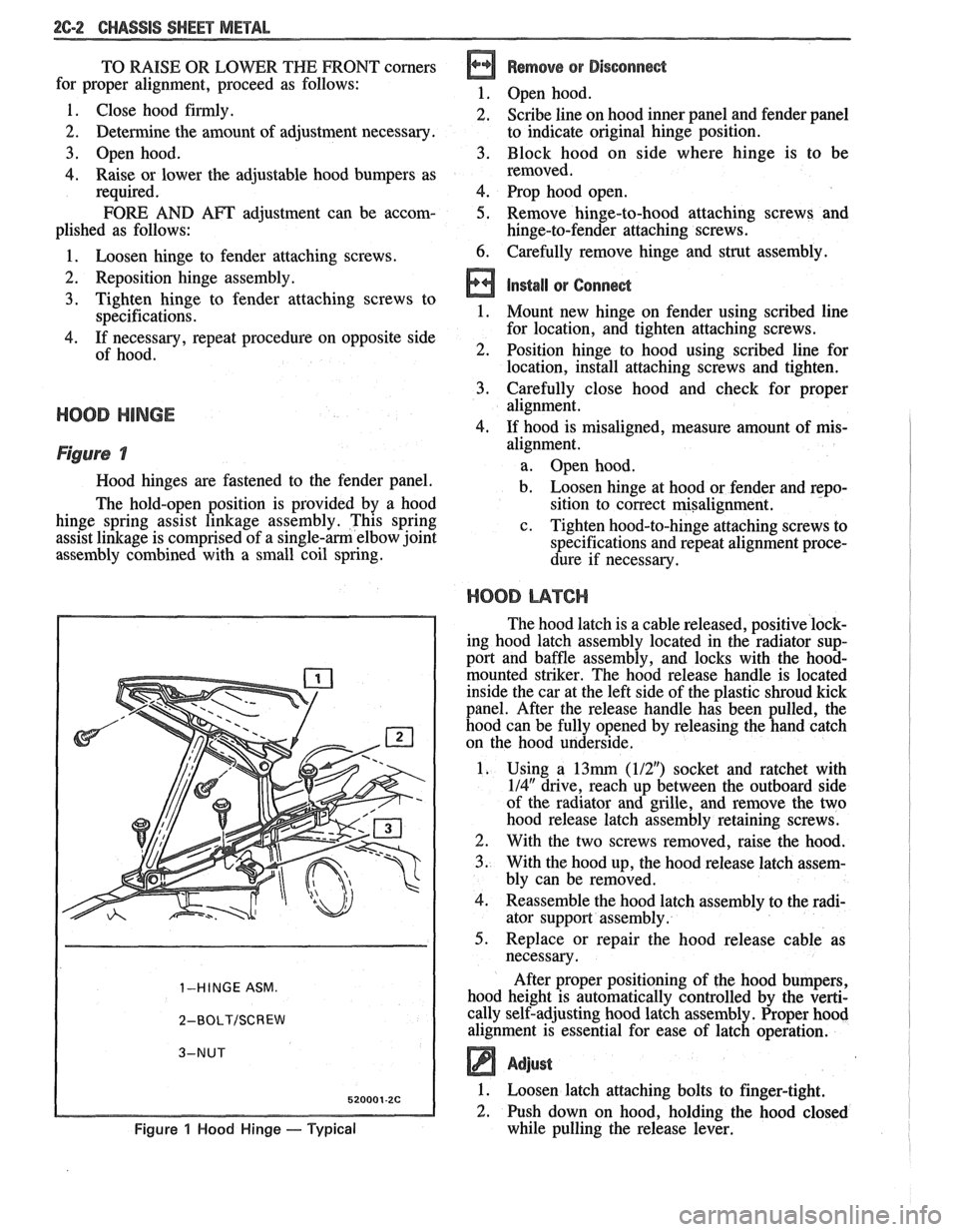
Figure 7
Hood hinges are fastened to the fender panel.
The hold-open position is provided by a hood
hinge spring assist linkage assembly. This spring
assist linkage is comprised of a
single-am elbow joint
assembly combined with a small coil spring.
1-HINGE ASM.
2-BOLT/SCREW
Figure 1 Hood Hinge - Typical
alignment.
a. Open hood.
b. Loosen hinge at hood or fender and repo-
sition to correct misalignment.
c. Tighten hood-to-hinge attaching screws to
specifications and repeat alignment proce-
dure if necessary.
HOOD L14TCI-I
The hood latch is a cable released, positive lock-
ing hood latch assembly located in the radiator sup-
port and baffle assembly, and locks with the
hood-
mounted striker. The hood release handle is located
inside the car at the left side of the plastic shroud kick
panel. After the release handle has been pulled, the
hood can be fully opened by releasing the hand catch
on the hood underside.
1. Using a
13mrn (112") socket and ratchet with
114" drive, reach up between the outboard side
of the radiator and grille, and remove the two
hood release latch assembly retaining screws.
2. With the two screws removed, raise the hood.
3. With the hood up, the hood release latch assem-
bly can be removed.
4. Reassemble the hood latch assembly to the radi-
ator support assembly.
5. Replace or repair the hood release cable as
necessary.
After proper positioning of the hood bumpers,
hood height is automatically controlled by the verti-
cally self-adjusting hood latch assembly. Proper hood
alignment is essential for ease of latch operation.
Adjust
1. Loosen latch attaching bolts to finger-tight.
2. Push down on hood, holding the hood closed
while pulling the release lever.
Page 300 of 1825
BRAKES 5-7
ONmCAR SERVICE
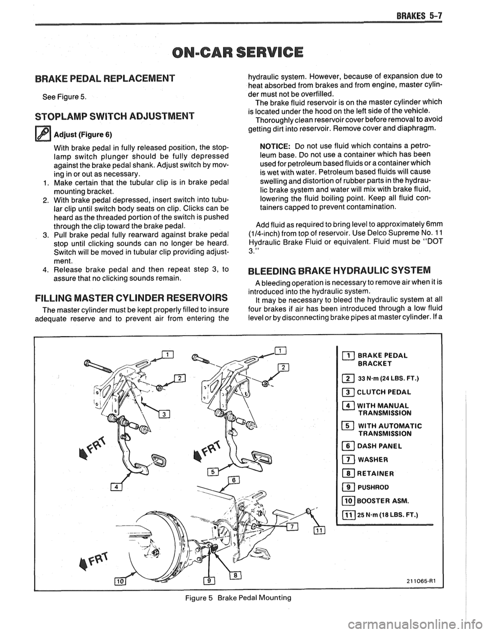
BRAKE PEDAL REPLACEMENT
See Figure 5.
STOPLAMP SWITCH ADJUSTMENT
Adjust (Figure 6)
With brake pedal in fully released position, the stop-
lamp switch plunger should be fully depressed
against the brake pedal shank. Adjust switch by mov-
ing in or out as necessary.
1. Make certain that the tubular clip is in brake pedal
mounting bracket.
2. With brake pedal depressed, insert switch into tubu-
lar clip until switch body seats on clip. Clicks can be
heard as the threaded portion of the switch is pushed
through the clip toward the brake pedal.
3. Pull brake pedal fully rearward against brake pedal
stop until clicking sounds can no longer be heard.
Switch will be moved in tubular clip providing adjust-
ment.
4. Release brake pedal and then repeat step 3, to
assure that no clicking sounds remain.
FILLING MASTER CYLINDER RESERVOIRS
The master cylinder must be kept properly filled to insure
adequate reserve and to prevent air from entering the hydraulic
system. However, because of expansion due to
heat absorbed from brakes and from engine, master cylin-
der must not be overfilled.
The brake fluid reservoir is on the master cylinder which
is located under the hood on the left side of the vehicle.
Thoroughly clean reservoir cover before removal to avoid
getting dirt into reservoir. Remove cover and diaphragm.
NOTICE: Do not use fluid which contains a petro-
leum base. Do not use a container which has been
used for petroleum based fluids or a container which
is wet with water. Petroleum based fluids will cause
swelling and distortion of rubber parts in the hydrau-
lic brake system and water will mix with brake fluid,
lowering the fluid boiling point. Keep all fluid con-
tainers capped to prevent contamination.
Add fluid as required to bring level to
approximately6mm
(114-inch) from top of reservoir. Use Delco Supreme No. 1 1
Hydraulic Brake Fluid or equivalent. Fluid must be "DOT
3."
BLEEDING BRAKE HYDRAULIC SYSTEM
A bleeding operation is necessary to remove air when it is
introduced into the hydraulic system. It may be necessary to bleed the hydraulic system at all
four brakes if air has been introduced through a low fluid
level or by disconnecting brake pipes at master cylinder. If a
Figure
5 Brake Pedal Mounting
Page 1601 of 1825
88-2 LIGHTING SYSTEMS AND HORNS
The fog lights must be aimed for proper
illumination of the road. Fog light
aim should be
checked: at least once a year; when a new light housing
is installed; or if service or repairs in the front end area
have (or may have) disturbed the fog light mountings.
FRONT PARKING/TURM SIGNAL
LIGHTS - Pushing either side of the instrument panel
switch will turn on the front parking lights. (Pushing
the left side of the switch will also turn on the
headlights.) When the ignition is on and the turn signal
lever is moved, the appropriate front parking light
flashes to signal a turn. Both lights will flash when the
hazard flashers are on.
If the driver's door is opened when the parking
lights are on, a warning tone will sound. For more
information, see Section
8A-77.
HAZARD FLASHERS - The hazard warning
flasher is part of the turn signal circuit. Pushing in the
button (on the right side of the steering column) will
cause the front and rear turn signal lights, and the front
sidemarker lights, to flash. Pull out the collar around
the button to turn off the hazard flashers.
The hazard flashers will work with the ignition
either off or on. When the hazard flashers are on, the
turn signals do not
work.
The hazard flashers will stop flashing and stay on
brightly if the brake pedal is pushed down.
HEADLIGHTS - The headlights are controlled
by the switch on the instrument panel (to the left of the
speedometer). They will come on whether or not the
ignition is turned on. Pushing the upper left side of the
switch turns on the headlights and causes the headlight
motors to raise the headlights. Pushing the bottom part
of the switch turns off the headlights, and they should
lower.
If the driver's door is opened when the ignition
is off and the headlights are on, a warning tone will
sound. For more information, see Section
8A-77.
Headlight low-beam and high-beam are
controlled by the turn
signal/multifunction lever on
the left side of the steering column. When the
headlights are on, pull the lever toward the steering
wheel until the switch clicks; the lights will change
from low-beam to high-beam, or from high-beam to
low-beam. An indicator light on the center instrument
cluster will come on when the high-beam headlights
are on.
The headlights must be aimed for proper
illumination of the road. Headlight aim should be
checked: at least once a year; when a new headlight
bulb is installed; or if service or repairs in the front end
area have (or may have) disturbed the headlights or
their mountings. The headlight bezels do not need to
be removed to aim the headlights.
Headlight focus is set when the sealed-beam unit
is made; no adjustment for focus is necessary or
possible.
Some state and local laws specify
requirements for headlight aim; these laws
must be followed.
LICENSE PLATE LBGHTS -A light above the
rear license plate will come on when the headlights or
parking lights are on.
LIGHT SWITCH - Most exterior lights are
controlled by the switch on the instrument panel, to the
left of the speedometer. Pushing the upper right part
of the switch turns on the front parking lights, the
taillights and the sidemarker lights. (It also turns on
the instrument panel lights.) Pushing the upper left
part of the switch turns on all these lights plus the
headlights. Pushing the bottom part of the switch turns
off all lights.
In some cases (such as going through a car wash),
it may be desirable to raise the headlights without
leaving the headlights on. To do so, push the upper
right part of the switch to turn on the parking lights.
Then, lightly push the upper right part of the switch;
the headlights will raise but will not turn on.
(Remember that the parking lights and taillights will
stay on.)
For more information on this switch (including
on-car service), see Section
8C. Also see Section 8C for
information on interior lights.
REAR TAlL/STOP/TURN SIGNAL
LIGHTS - The rear tail/stop/turn signal lights are
part of the same light assembly. Pushing either side of
the instrument panel switch turns on the taillights.
When the brake pedal is pushed down, the lights glow
brighter to serve as stoplights.
Moving the turn signal lever when the ignition is
on causes the appropriate rear lights to flash. (If the
brake pedal is held down and a turn is signalled, one
side will flash and the other will stay on brightly.)
All lights will flash when the hazard flashers are
on. However, if the brake pedal is pushed while the
hazard flashers are on, the lights will stop flashing and
stay on brightly.
SIDEMARKER LIGHTS -The front and rear
sidemarker lights will come on when the headlights or
parking lights are on. Both front and rear sidemarker
lights also have reflectors; they will shine when struck
by light, whether or not the car's lights are on.
If the headlights or parking lights are off when a
turn is signalled, the front sidemarker light will flash
in unison with the front turn signal light on the same
side. If the lights are on when a turn is signalled, the
front
sidemarker light and front turn signal light flash
alternately.
TURN SlG N ALS - The front turn signals are
combined with the front parking lights. The rear turn
signals are part of the rear
tail/stop/turn signal lights.
The turn signals work only when the ignition is on, and
the hazard flashers are turned off.
The turn signals are controlled by the turn
signal/multifunction lever on the left side of the
steering column. Moving the lever all the way up or
down (past the detent) will turn on the turn signals.
When the turn is completed, the lever will return to
neutral and the turn signals will stop flashing.
For changing lanes or shallow turns where the
steering wheel does not move far enough to cancel the
signal, move the turn signal lever only to the first
detent. When the lever is released, it will return to
neutral and the turn signals will cancel.
UNDERHOOD LIGHT - The underhood light
will come on when the hood is raised.
Page 1710 of 1825
FRONT END - F STYLE 41-1-1
SECTION 4H
FRONT END
NOTICE: The anti-theft label found on some major sheet metal, engines, and transmissions must be masked
prior to painting, rustproofing, undercoating, etc. The
mask must be removed following the above operations.
Failure to keep the label clean and readable may result in liability for violation of Federal Vehicle Theft Prevention
Standard, and subject the vehicle owner to possible suspicion that the part was stolen.
CONTENTS
.............................................................................................................. Body Ventilation 4H- 1
Shroud Side Trim Finishing Panel ................................................................................ 4H- 1
Pressure Relief Valve .................................................................................................. 4H- 1
Hood Latch Release Cable ............................................................................................ 4H- 1
The body ventilation system on styles without air
conditioning consists of a fresh air intake located at the
front plenum chamber. Air enters the front plenum
chamber through an air intake grille screen (Fig.
1).
Air passes through the plenum chamber to air outlet
doors. When ventilation controls are operated, air
enters past the doors and into the body from outlets in
the dash panel. The air then passes through the body,
around the rear seat, into the rear compartment to the
rear quarters and leaves the body passing through the
pressure relief valves on the rear body lock pillars (Fig.
4). For complete instructions on operation of the body
ventilation system, refer to the owner's manual.
Water entering the plenum chamber is drained
through openings provided for that purpose.
FRONT END SEALING
All potential waterleak locations are sealed in
production with high quality durable sealers. Should it
be necessary to reseal specific areas, a high quality
medium-bodied sealer which will remain flexible after
curing and can be painted should be used.
SHROUD SIDE TRIM FINISHING PANEL
Removal and Installation
1. Remove shroud side trim finishing panel screws
(Fig. 2).
2. Pull down and rearward on trim finishing panel
to release hood cable handle from slot on left side.
On right side, pull rearward to remove panel from
windshield lower side garnish (Figs.
2 and 3).
3. To install, reverse removal procedures.
PRESSURE RELIEF VALVE
The pressure relief valves are attached to rear
lock pillars (in door opening below belt) with screws.
Figure
4 shows pressure relief valve installations.
Removal and Installation
1. Remove louver-to-lock pillar screw located in the
door opening (Fig.
4).
2. Slide louver up to disengage hook-type attaching
clip to complete removal.
3. To install, reverse removal procedure.
HOOD LATCH RELEASE CABLE
The one-piece hood latch release cable includes
pull handle, control cable and housing. The control
cable is installed through the left shroud side trim
panel. A sealing grommet attached to the dash panel
completes the assembly (Figs. 2 and
5).
Removal and Installation
The shroud side finishing panels are designed
with an integral hinge pillar pinchweld finishing lace.
The left side has a cutout slot for the hood release cable
handle. There is no need to remove the cable assembly
2.
when removing the trim finishing panel. The trim 3.
finishing panel is secured to the side shroud with
self-tapping attaching screws.
4.
Raise hood and disengage cable from hood latch
assembly. Block latch to prevent hood locking
until cable has been reinstalled.
Remove left shroud side trim panel.
Disengage control assembly housing from cutout
of trim panel and remove
cable assembly from
panel.
To install, reverse the removal procedure.