1988 PONTIAC FIERO alarm
[x] Cancel search: alarmPage 1166 of 1825
CONTENTS
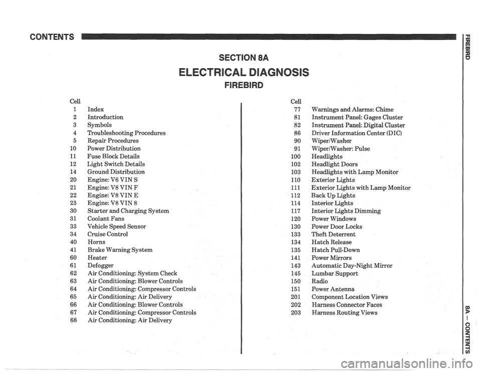
ELECTRICAL DIAGNOSIS
Cell
1
2
3
4 5
10
11
12 14
20
21
22
23
30
31
33
34
40
4
1
60
61
62
63
64
65
66
67
68
Index
Introduction
Symbols
Troubleshooting Procedures Repair Procedures
Power Distribution
Fuse Block Details
Light Switch Details
Ground Distribution
Engine:
V6 VIN S
Engine: V8 VIN
F
Engine: V8 VIN E
Engine:
V8 VIN 8
Starter and Charging System
Coolant Fans
Vehicle Speed Sensor
Cruise Control Horns
Brake Warning System
Heater
Defogger
Air Conditioning: System Check
Air Conditioning: Blower Controls
Air Conditioning: Compressor Controls
Air Conditioning: Air Delivery
Air Conditioning: Blower Controls
Air Conditioning: Compressor Controls
Air Conditioning: Air Delivery Cell
77
8
1
82
86 90
9
1
100
102
103
110
111
112
114
117
120
130
133
134
135
141
143
145
150
151
201 202
203
Warnings and Alarms: Chime
Instrument Panel: Gages Cluster
Instrument Panel:
Digital Cluster
Driver Information Center
(DIC)
WiperlWasher
WiperlWasher: Pulse
Headlights
Headlight Doors
Headlights with Lamp Monitor
Exterior Lights
Exterior Lights with Lamp Monitor
Back Up Lights
Interior Lights
Interior Lights Dimming
Power Windows
Power Door Locks
Theft Deterrent
Hatch Release
Hatch Pull-Down
Power Mirrors
Automatic Day-Night Mirror
Lumbar Support
Radio Power Antenna
Component Location Views
Harness Connector Faces
Harness Routing Views
Page 1167 of 1825
Page
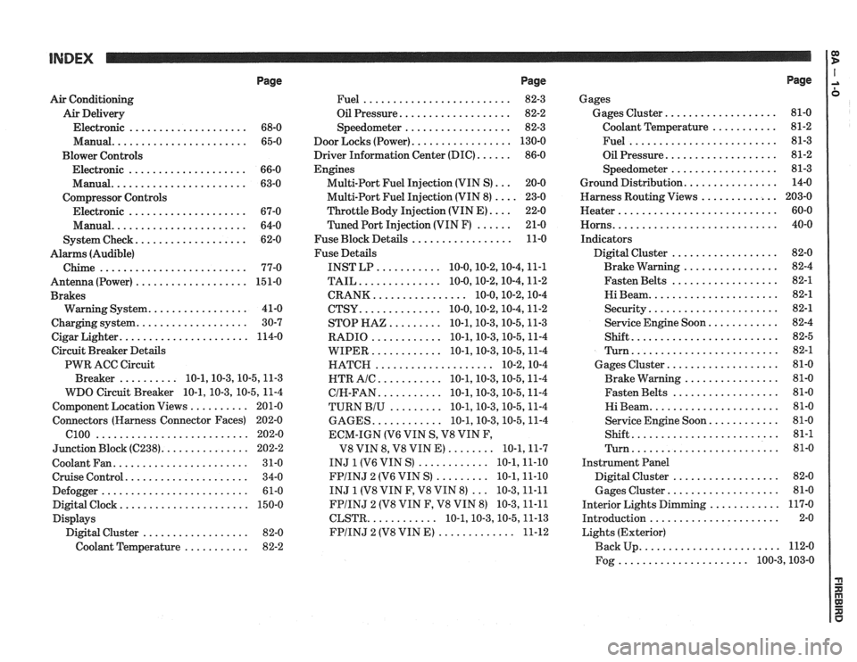
Air Conditioning
Air Delivery
Electronic
.................... 68-0
Manual
....................... 65-0
Blower Controls
Electronic
.................... 66-0
Manual
....................... 63-0
Compressor Controls Electronic
.................... 67-0
Manual
....................... 64-0
................... System Check 62-0
Alarms (Audible)
Chime
......................... 77-0
Antenna(Power) ................... 151-0
Brakes
................. Warning System 41-0
................... Charging system 30-7
...................... Cigar Lighter 114-0
Circuit Breaker Details
PWR ACC Circuit
.......... Breaker 10.1.10.3.10.5.1 1.3
WDO Circuit Breaker
10.1. 10.3. 10.5. 11-4
.......... Component Location Views 201-0
Connectors (Harness Connector Faces) 202-0
el00 .......................... 202-0
............... Junction Block ((2238) 202-2
Coolant Fan
....................... 31-0
Cruise Control
..................... 34-0
Defogger
......................... 61-0
Digital Clock
...................... 150-0
Displays Digital Cluster
.................. 82-0
Coolant Temperature
........... 82-2
Page
......................... Fuel 82-3
................... Oil Pressure 82-2
.................. Speedometer 82-3
................. Door Locks (Power) 130-0
...... Driver Information Center (DIC) 86-0
Engines
... Multi-Port Fuel Injection (VIN S) 20-0
.... Multi-Port Fuel Injection (VIN 8) 23-0
.... Throttle
Body Injection (VIN E) 22-0
...... Tuned
Port Injection (VIN F) 21-0
................. Fuse Block Details 11-0
Fuse Details
........... INST LP 10.0.10.2.10.4.1 1.1
.............. TAIL 10.0.10.2.10.4.1 1.2
................ CRANK 10.0.10.2.1 0.4
.............. CTSY 10~0.10.2.10.4.1 1.2
......... STOP HAZ 10.1.10.3.10.5.1 1.3
............ RADIO 10.1.10.3.10.5.1 1.4
............ WIPER 10.1.10.3.10.5.1 1.4
.................... HATCH 10.2.1 0.4
........... HTR AlC 10.1.10.3.10.5.1 1.4
........... CIH.FAN 10.1.10.3.10.5.1 1.4
......... TURN BIU 10.1.10.3.10.5.1 1.4
............ GAGES 10.1.10.3.10.5.1 1.4
ECM-IGN
(V6 VIN S. V8 VIN F.
........ V8 VIN 8. V8 VIN E) 10.1.1 1.7
............ INJ 1 (V6 VIN S) 10.1.1 1.10
......... FPIINJ 2 (V6 VIN S) 10.1.1 1.10
... INJ 1 (V8 VIN F. V8 VIN 8) 10.3.1 1.11
FPIINJ 2 (V8 VIN F. V8 VIN 8) 10.3.1 1.11
............ CLSTR 10.1.10.3.10.5.1 1.13
............. FPIINJ 2 (V8 VIN E) 11-12
Page
Gages
................... Gages Cluster 81-0
........... Coolant Temperature 81-2
......................... Fuel 81-3
................... Oil Pressure 81-2
.................. Speedometer 81-3
................ Ground Distribution 14-0
Harness Routing Views
............. 203-0
........................... Heater 60-0
............................ Horns 40-0
Indicators
.................. Digital Cluster 82-0
................ Brake Warning 82-4
.................. Fasten Belts 82-1
...................... Hi Beam 82-1
...................... Security 82-1
............ Service Engine Soon 82-4
......................... Shift 82-5
......................... Turn 82-1
................... Gages Cluster 81-0
................ Brake Warning 81-0
.................. Fasten Belts 81-0
...................... Hi Beam 81-0
............ Service Engine Soon 81-0
......................... Shift 81-1
......................... Turn 81-0
Instrument Panel
Digital Cluster
.................. 82-0
Gages Cluster
................... 81-0
............ Interior Lights Dimming 117-0
...................... Introduction 2-0
Lights (Exterior)
........................ Back Up 112-0
...................... Fog 100.3,10 3.0
Page 1393 of 1825
WARNINGS AND ALARMS: CHIME l e
Page 1394 of 1825
WARNINGS AND ALARMS: CHIMES
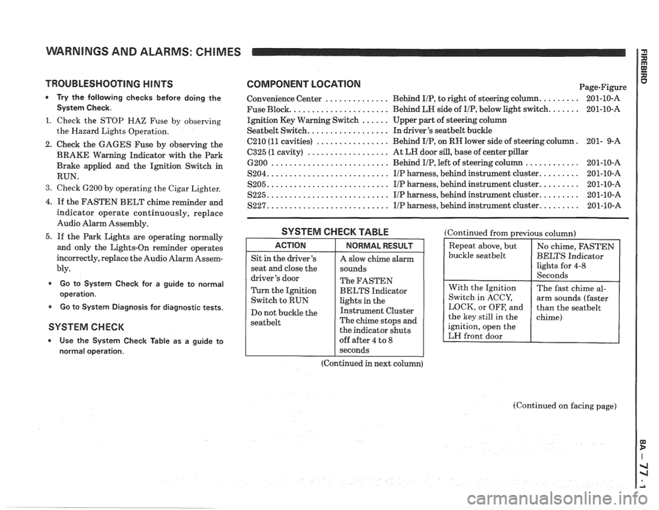
TROUBLESHOOTING H lNTS
* Try the following checks before doing the
System Check.
1. Check the STOP HAZ Fuse by observing
the Hazard Lights Operation.
2. Check the GAGES Fuse by observing the
BRAKE Warning Indicator with the Park
Brake applied and the Ignition Switch in
RUN.
3. Check 6200 by operating the Cigar Lighter.
4. If the FASTEN BELT chime reminder and
indicator operate continuously, replace
Audio Alarm Assembly.
5. If the Park Lights are operating normally
and only the Lights-On reminder operates
incorrectly, replace the Audio Alarm Assem-
bly.
Go to System Check for a guide to normal
operation.
Go to System Diagnosis for diagnostic tests.
SYSTEM CHECK
* Use the System Check Table as a guide to
normal operation.
COMPONENT LOCATlON Page-Figure
Convenience Center
.............. Behind IIP, to right of steering column. ........ 201-10-A
Fuse Block.
..................... Behind LH side of IIP, below light switch. ...... 201-10-A
Ignition Key Warning Switch
...... Upper part of steering column
Seatbelt Switch. ................. In driver's seatbelt buckle
C210
(11 cavities) ................ Behind IIP, on RH lower side of steering column. 201-
9-A
6325 (1 cavity) .................. At LH door sill, base of center pillar
6200 .......................... Behind IIP, left of steering column ............ 201-10-A
S204. .......................... IIP harness, behind instrument cluster. ........ 201-10-A
S205. .......................... IIP harness, behind instrument cluster. ........ 201-10-A
S225. .......................... I/P harness, behind instrument cluster. ........ 201-10-A
S227. .......................... IIP harness, behind instrument cluster. ........ 201-10-A
SYSTEM CHECK TABLE
ACTION
Sit in the driver's
seat and close the
driver's door
Turn the Ignition
Switch to RUN
Do not buckle the
seatbelt
NORMAL RESULT
A slow chime alarm
sounds
The FASTEN
BELTS Indicator
lights in the
Instrument Cluster
The chime stops and
the indicator shuts
off after 4 to
8
(Continued from previous column)
buckle
seatbelt
ignition, open the
LH front door
I seconds
(Continued in next column)
(Continued on facing page)
Page 1395 of 1825
WARNINGS AND ALARMS: CHIMES I
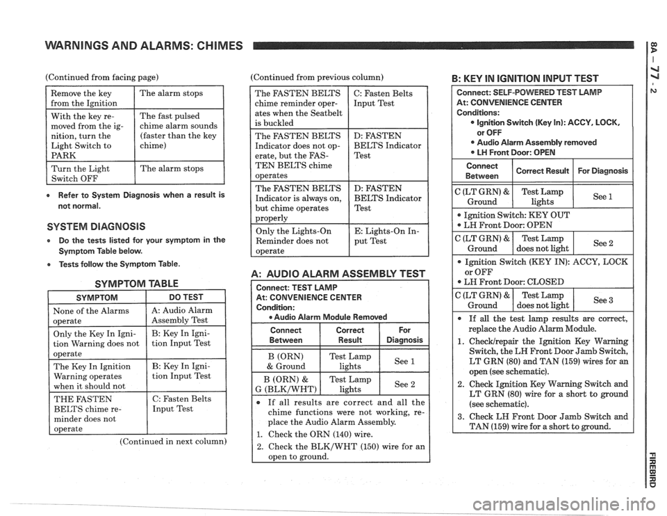
(Continued from facing page) (Continued from previous column) B: KEY IN IGNITION INPUT TEST
e Refer to System Diagnosis when a result is
not normal.
SYSTEM DIAGNOSIS
Do the tests listed lor your symptom in the
Symptom Table below.
e Tests follow the Symptom Table.
SYMPTOM TABLE
SYMPTOM DO TEST I
1 None of the Alarms 1 A: Audio Alarm I
(Continued in next column)
A: AUDIO ALARM ASSEMBLY TEST
At: CONVENIENCE CENTER
e Audio Alarm Module Removed
The FASTEN BELTS
chime reminder oper-
ates when the
Seatbelt
is buckled
The FASTEN BELTS
Indicator does not op-
erate, but the
FAS-
TEN BELTS chime
operates
The FASTEN BELTS
Indicator is always on,
but chime operates
properly
Only the Lights-On
Reminder does not
operate
Connect Correct
Between
I Result Diasnosis
C: Fasten Belts
Input Test
D: FASTEN
BELTS Indicator
Test
D: FASTEN
BELTS Indicator
Test
E: Lights-On In-
put Test
If all results are correct and all the
chime functions were not working, re-
place the Audio Alarm Assembly.
1. Check the ORN (140) wire.
2. Check the BLK/WHT (150) wire for an
oDen to ground.
At: CONVENIENCE CENTER
LT GRN (80) and TAN (159) wires for an
open (see schematic).
2. Check Ignition Key Warning Switch and
LT GRN (80) wire for a short to ground
(see schematic).
Page 1396 of 1825
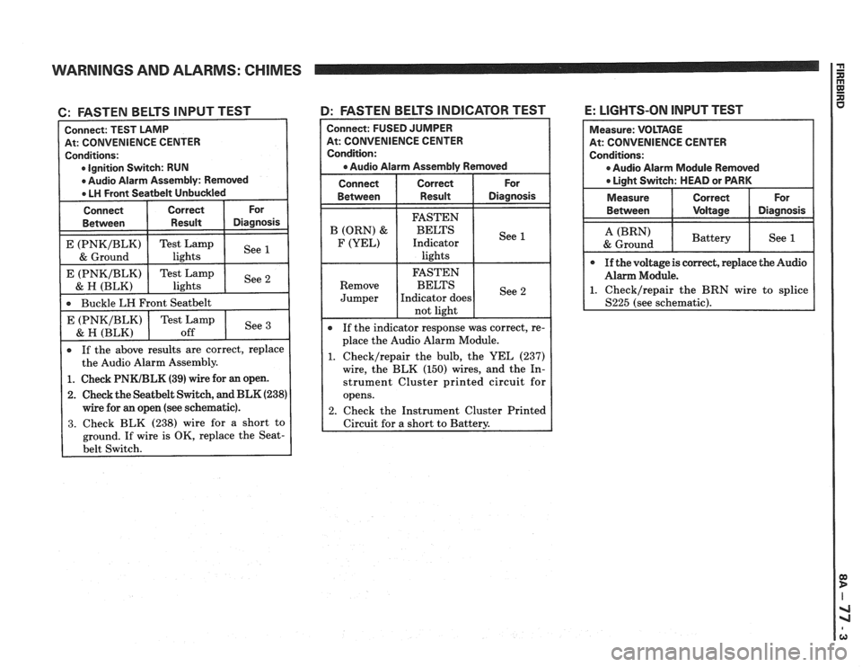
WARNINGS AND ALARMS: CHIMES
6: FASTEN BELTS INPUT TEST
At: CONVENIENCE CENTER
Ignition Switch: RUN
If the above results are correct, replace
the Audio Alarm Assembly.
Buckle
LH Front
Seatbelt
1. Check PNKIBLK (39) wire for an open.
2. Check the Seatbelt Switch, and BLK (238)
wire for an open (see schematic).
3. Check BLK (238) wire for a short to
ground. If wire is OK, replace the
Seat-
4: FASTEN BELTS INDICATOR TEST
See E (PNKIBLK)
& H (BLK)
Connect: FUSED JUMPER
At: CONVENIENCE CENTER
Condition:
a Audio Alarm Assembly Removed
Connect Correct For
Between Result Diagnosis
Test Lamp
off If
the indicator response was correct, re-
place the Audio Alarm Module.
1. Checklrepair the bulb, the YEL (237)
wire, the BLK (150) wires, and the In-
strument Cluster printed circuit for
opens.
2. Check the Instrument Cluster Printed
Circuit for
a short to Battery.
E: LIGHTS-ON INPUT TEST
At: CONVENIENCE CENTER
0 Audio Alarm Module Removed
Page 1397 of 1825
WARNINGS AND ALARMS: CHIMES
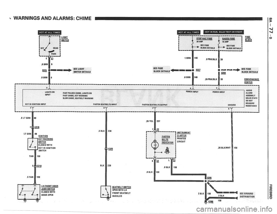
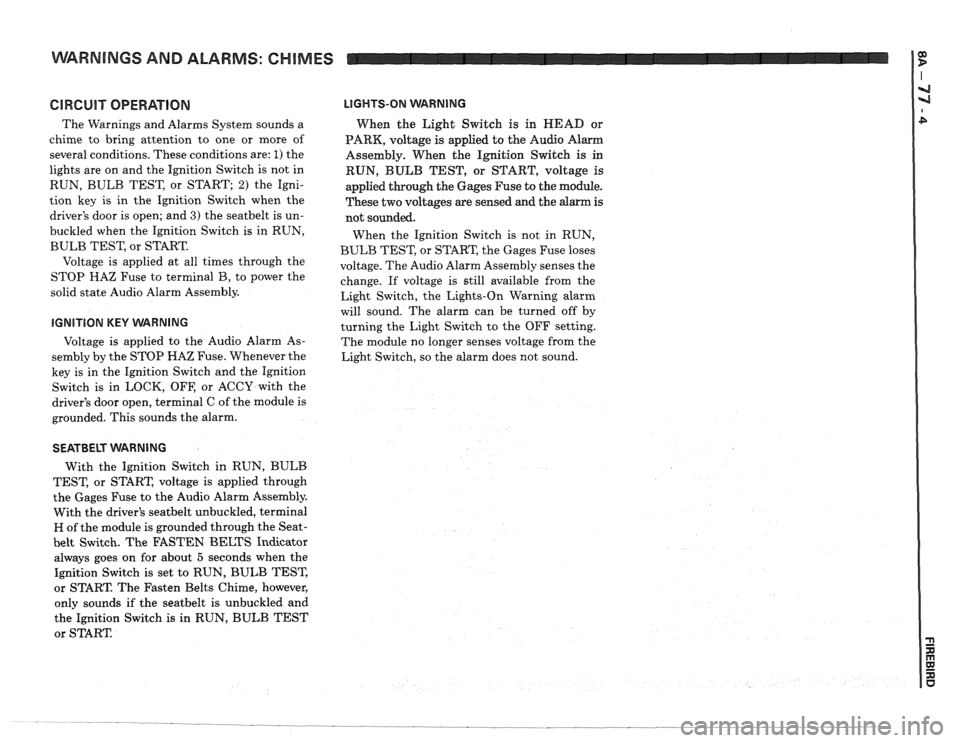
GlRGUlT OPERATION
The Warnings and Alarms System sounds a
chime to bring attention to one or more of
several conditions. These conditions are:
1) the
lights are on and the Ignition Switch is not in
RUN, BULB TEST, or START;
2) the Igni-
tion key is in the Ignition Switch when the
driver's door is open; and
3) the seatbelt is un-
buckled when the Ignition Switch is in RUN,
BULB TEST, or START.
Voltage is applied at all times through the
STOP
HAZ Fuse to terminal B, to power the
solid state Audio Alarm Assembly.
IGNITION KEY VVARNING
Voltage is applied to the Audio Alarm As-
sembly by the STOP HAZ Fuse. Whenever the
key is in the Ignition Switch and the Ignition
Switch is in LOCK, OFF, or ACCY with the
driver's door open, terminal C of the module is
grounded. This sounds the alarm.
LIGHTS-ON WARNING
When the Light Switch is in HEAD or
PARK, voltage
is applied to the Audio Alarm
Assembly. When the Ignition Switch
is in
RUN, BULB TEST, or START, voltage is
applied through the Gages Fuse to the module.
These two voltages are sensed and the alarm is
not sounded.
When the Ignition Switch is not in RUN,
BULB TEST, or START, the Gages Fuse loses
voltage. The Audio Alarm Assembly senses the
change. If voltage is still available from the
Light Switch, the Lights-On Warning alarm
will sound. The alarm can be turned off by
turning the Light Switch to the OFF setting.
The module no longer senses voltage from the
Light Switch, so the alarm does not sound.
SEATBELT WARNING
With the Ignition Switch in RUN, BULB
TEST, or START, voltage is applied through
the Gages Fuse to the Audio Alarm Assembly.
With the driver's
seatbelt unbuckled, terminal
H of the module is grounded through the Seat-
belt Switch. The FASTEN BELTS Indicator
always goes on for about
5 seconds when the
Ignition Switch is set to RUN, BULB TEST,
or START. The Fasten Belts Chime, however,
only sounds if the
seatbelt is unbuckled and
the Ignition Switch
is in RUN, BULB TEST
or START
Page 1406 of 1825
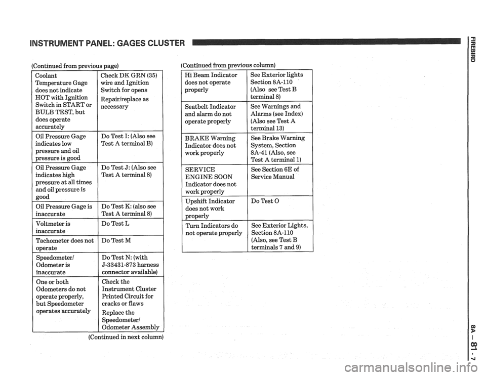
INSTRUMENT PANEL: GAGES CLUSTER
I Oil Pressure Gage
(Continued from previous page)
indicates low
pressure
and oil
pressure is good
Coolant
Temperature Gage
does not indicate
HOT with Ignition
Switch in START or
BULB TEST, but
does operate
accurately
Do Test I: (Also see
Test A
terminal B)
Check DK GRN (35)
wire and Ignition
Switch for opens
Repairlreplace as
necessary
Oil Pressure Gage
indicates high
pressure at
all times
and oil pressure is
good Do
Test
J: (Also see
Test A terminal
8)
Oil Pressure Gage is
inaccurate Do
Test K: (also see
Test A terminal
8)
Do Test L
Tachometer does not
operate
Speedometer1
Odometer is
inaccurate Do
Test M
Do Test N: (with
5-33431-873 harness
connector available)
One or both
Odometers do not
operate properly,
but Speedometer
operates accurately
I
Check the
Instrument Cluster
Printed Circuit for
cracks or flaws
Replace the
Speedometer1
Odometer Assembly
(Continued in next column) (Continued from previous
column)
Hi Beam Indicator
does not operate
properly See
Exterior lights
Section 8A-110
(Also see Test
B
terminal 8)
I operate properly
I
(Also see Test A
I
Seatbelt Indicator
and alarm do not
BRAKE Warning Indicator does not
work properly
I
See Warnings and
Alarms (see Index)
SERVICE
ENGINE SOON
Indicator does not
does not work See
Brake Warning
System, Section
8A-41 (Also, see
Test A terminal
1)
See Section 6E of
1 Service Manual
Do Test O
r
(Also, see Test B
terminals 7 and
9)