1988 PONTIAC FIERO wiring diagram
[x] Cancel search: wiring diagramPage 36 of 1825
HEATING AND VENTILATION 1.4-1 3
ON-VEHICLE SERVICE
HEATER ELECTRICAL WIRING
The heater wiring diagrams are shown in
Electrical Diagnosis, Section
8A, and should be
referred to for diagnosis of electrical problems in the
heater system.
HEATER CONTROL ASSEMBLY AND BLOWER
SWITCH
Remove or Disconnect
1. Negative battery cable.
2.
Control/radio console trim plate.
3. Three
(3) controller retaining screws and pull
controller out from console.
4. Control cables and electrical connections.
5. Blower switch from controller if either switch or
controller requires replacement. If controller is
being replaced, transfer blower switch to new
controller.
Install or Connect
1. When installing controller, install lower right
screw first to properly align controller in console.
2. Blower switch to controller.
3. Control cables and electrical connections.
4. Three (3) controller retaining screws and
controller to console.
5. Control/radio console trim plate.
6. Negative battery cable.
TEMPERATURE CONTROL, POWER VENT,
HEATER DEFROST CABLE
Remove or Disconnect
1. Hush panel(s) (see Section 8C):
a. Temperature
cable - R.H. hush panel.
b.
Heateddefrost cable - R.H. hush panel.
c. Vent
cable
- L.H. hush panel.
2.
Control/radio console trim plate.
3. Three (3) controller retaining screws and pull
controller out from console.
4. Control cable requiring replacement at control
end.
5. Cable at mode control end (temperature cable:
remove cable link cover at crank location).
Install or Connect
1. When installing controller, install right lower
screw first to align control in console.
2. Cable
at mode control end (temperature cable:
install cable link cover at crank location).
3. Control cable at control end.
4. Three (3) controller retaining screws and
contoller in console.
5. Control/radio console trim plate.
6. Hush panel(s) (see Section 8C).
7. Fully cycle controls to adjust cables and check for
proper operation.
HEATER CORE
Remove or Disconnect
Battery ground cable.
Drain cooling system.
Heater inlet and outlet hoses from heater core.
Right lower hush panel (see Section
8C).
ECM attaching screw and move aside.
Right lower I.P. trim panel (see Section
8C).
Lower right I.P. carrier-to-cowl screw.
Four (4) heater case cover screws. Upper left screw
may be reached with a long socket extension through
the I.P. openings exposed by removal of the lower
right I.P. trim panel. Carefully lift the lower right
corner of the I.P. to align socket extension.
Heater case cover.
Core support plate and baffle screws.
Heater core, support plate and baffle from case.
Install or Connect
1. Heater core, support plate and baffle to case.
2. Core support
plate and baffle screws.
3. Heater case cover.
4. Four (4) heater case cover screws.
5. Lower right I.P. carrier-to-cowl screw.
6. Right lower I.P. trim panel (see Section 8C).
7. ECM.
8. Right lower hush panel (see Section
8C).
9. Heater inlet and outlet hoses to heater core.
10. Refill cooling system and check for leaks.
11. Battery ground cable.
VENT CONTROL CABLE (RAM VENT)
Remove or Disconnect 1
1. Hush panel(s) (see Section 8C). R.H. cable
replacement will require removal of both L.H.
and R.H. hush panels.
2. Two
(2) retaining screws and individual vent
control.
3. Unclip
cable control clamp at vent duct and
disengage formed end of cable from door lever.
1 Install or Connect
1. Cable control clamp at vent duct and install
formed end of cable on door lever.
2, Two (2) retaining screws and individual vent
control.
3. Hush
panel@) (see Section 8C).
4. Cycle
control fully and check for proper
operation.
HEATER CONTROL WIRING I
Remove or Disconnect
1. Negative battery cable.
Page 46 of 1825
AIR CONDITIONING 1 B-3
A low-side pressure Schrader valve service fit-
ting is located near the top of the accumulator. A
similar Schrader fitting may be provided for mounting
the pressure cycling switch. It is not necessary to dis-
charge the system to replace the switch. The accumu-
lator is serviced only as a replacement assembly.
Heater Core
The heater core heats the air before it enters the
car. Engine coolant is circulated through the core to
heat the outside air passing over the fins of the core.
The core is functional at all times (no water valve) and
may be used to temper conditioned air in
A/C mode,
as well as heat or vent mode.
SYSTEM COMPONENTS --- CON"FOL
Controller
The operation of the A/C system is controlled by
the switches and the lever on the control head. The
compressor clutch and blower are connected electri-
cally to the control head by a wiring harness. The
blower circuit is open in the off mode and air flow is
provided by the four blower speeds available in the
remaining modes. Cooled and dehumidified air is
available in the max, normal, bi-level and defrost
modes.
Temperature is controlled by the position of the
temperature lever on the control head. A cable con-
nects this lever to the temperature door which controls
air flow through the heater core. As the temperature
lever is moved through its range of travel, a sliding
clip on the cable at the temperature valve connection
should assume a position assuring that the temperature
door will seat in both extreme positions. Temperature
door position is independent of mode selection. The
temperature cable attaches to the right side of the air
conditioning module. The temperature door on some
models is controlled electrically, thereby eliminating
the need for the temperature cable.
The electric engine cooling fan on some cars is
not part of the
A/C system; however, the fan is
operational any time the
A/C control is in Max.,
Norm, or Bi-Level modes. Some models provide for
engine cooling fan operation when the controller is in
the defrost mode. This added feature is part of the
A/C
controller function and is aimed at preventing exces-
sive compressor head temperatures. It also allows the
A/C system to function more efficiently. On some
models during road speed (above
35 mph) conditions
when air flow through the condenser coil is adequate
for efficient cooling, the engine cooling fan will be
turned off. The operation of the cooling fan is con-
trolled by the ECM through the cooling fan relay.
Complete wiring diagrams and diagnosis for the
AIC Electrical System are in Section 8A. Section 8A
also contains additional diagnostic information
regarding air flows and vacuum logic.
Vacuum Lines
Vacuum lines are molded to a connector which
is attached to a vacuum control switch on the control
head assembly.
In case of leakage or hose collapse, it will not be
necessary to replace the entire harness assembly.
Replacement can be made by cutting the hose and
inserting a plastic connector. If an entire hose must be
replaced, cut all hoses off at the connector and then
attach hoses directly to the control head vacuum
switch. (NOTE: The Fiero uses an electric motor to
control mode selection. Therefore, it will not have a
vacuum harness.
)
Vacuum Tank
During heavy acceleration, the vacuum supply
from the carburetor drops. A check valve in the vac-
uum tank maintains vacuum so that, under load condi-
tions, vacuum will be available for continuous use.
REWVS AND SWITCHES
High-Pressure Compresssr Gut-OFF Switch
The high-side, high-pressure cut-off switch in
the rear head of the compressor is a protective device
intended to prevent excessive compressor head pres-
sures and reduce the chance of refrigerant escape
through a safety relief valve. Normally closed, this
switch will open the circuit at a high-side pressure of
approximately 2700
kPa (430 psi 9 20 psi) and
reclose the circuit at approximately 1379 kPa (200 psi
9 50 psi).
Lsw-Pressure Cut-On Switch
Compressor protection is provided on some cars
by a low-pressure cut-off switch which will open in
the event of a low-charge condition. This switch can
be located in the liquid line or in the rear head of the
compressor. This switch will also keep the compres-
sor from running during cold weather.
Pressure eyesing Switch
The refrigeration cycle (on and off operation of
the compressor) is controlled by a switch which
senses the low-side pressure as an indicator of evapo-
rator temperature. The pressure cycling switch is the
freeze protection device in the system and senses
refrigerant pressure on the suction side of the system.
This switch is located on a standard Schrader-type
valve low-side fitting. This switch also provides com-
pressor cut-off during cold weather.
Additional compressor protection results from
the operating characteristics of the low-side pressure
cycling system. If a massive discharge occurs or the
orifice tube becomes plugged, low-side pressures
could be insufficient to close the contacts of the pres-
sure switch. In the event of a low charge, insufficient
cooling accompanied by rapid compressor clutch
cycling will be noticed at high air temperatures.
Page 465 of 1825
8D3-2 CHARGING SYSTEM
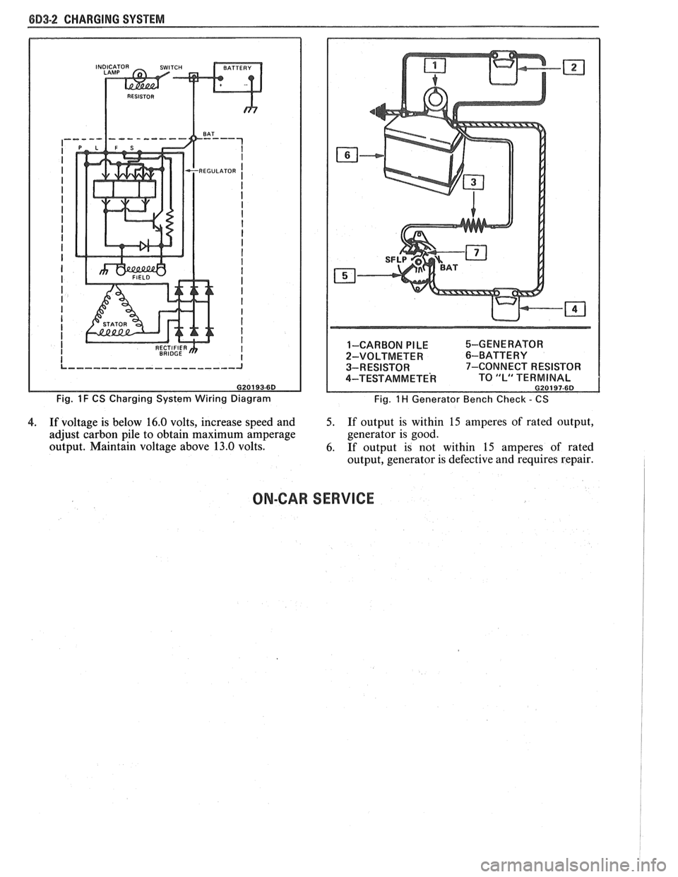
Fig. 1 F CS Charging System Wiring Diagram 1-CARBON
PILE %-GENERATOR
2-VOLTMETER
6-BATTERY
3-RESISTOR 7-CONNECT RESISTOR
4-TEST AM METE^ TO "L" TERMINAL G20197-6D
Fig. 1 H Generator Bench Check - CS
4. If voltage is below 16.0 volts, increase speed and 5. If output is within 15 amperes of rated output,
adjust carbon pile to obtain maximum amperage generator
is good.
output. Maintain voltage above 13.0 volts.
6. If output is not within
15 amperes of rated
output, generator is defective and requires repair.
ON-CAR SERVICE
Page 483 of 1825
8B-2 ENGINE ELECTRICAL
NO CRANKING, NO SOUND FROM SOLENOID
I TURN HEADLIGHTS AND DME LITE ON
TURN KEY TO START I
TEST BETTERY.
IF OK. REPAIR
.5 VOLT OR MORE a
OSITION, (POS. LEAD 0
GROUND CABLE CONN. ANDlOR REPLACE
CABLE.
CLEAN AND TIGHTEN
POS. BATTERY CABLE
TERMINALS
ANDlOR REPLACE CABLE. CONNECTOR.
FUSIBLE
CHECK CONNECTIONS
AND VOLTAGE AT
SOLENOID
"S' TERM.
LESS THAN
7 VOLTS b
FAULTY PURPLE WITH KEY IN START,
WIRE TO STARTER CHECK
VOLTAGE AT
G20201-6D
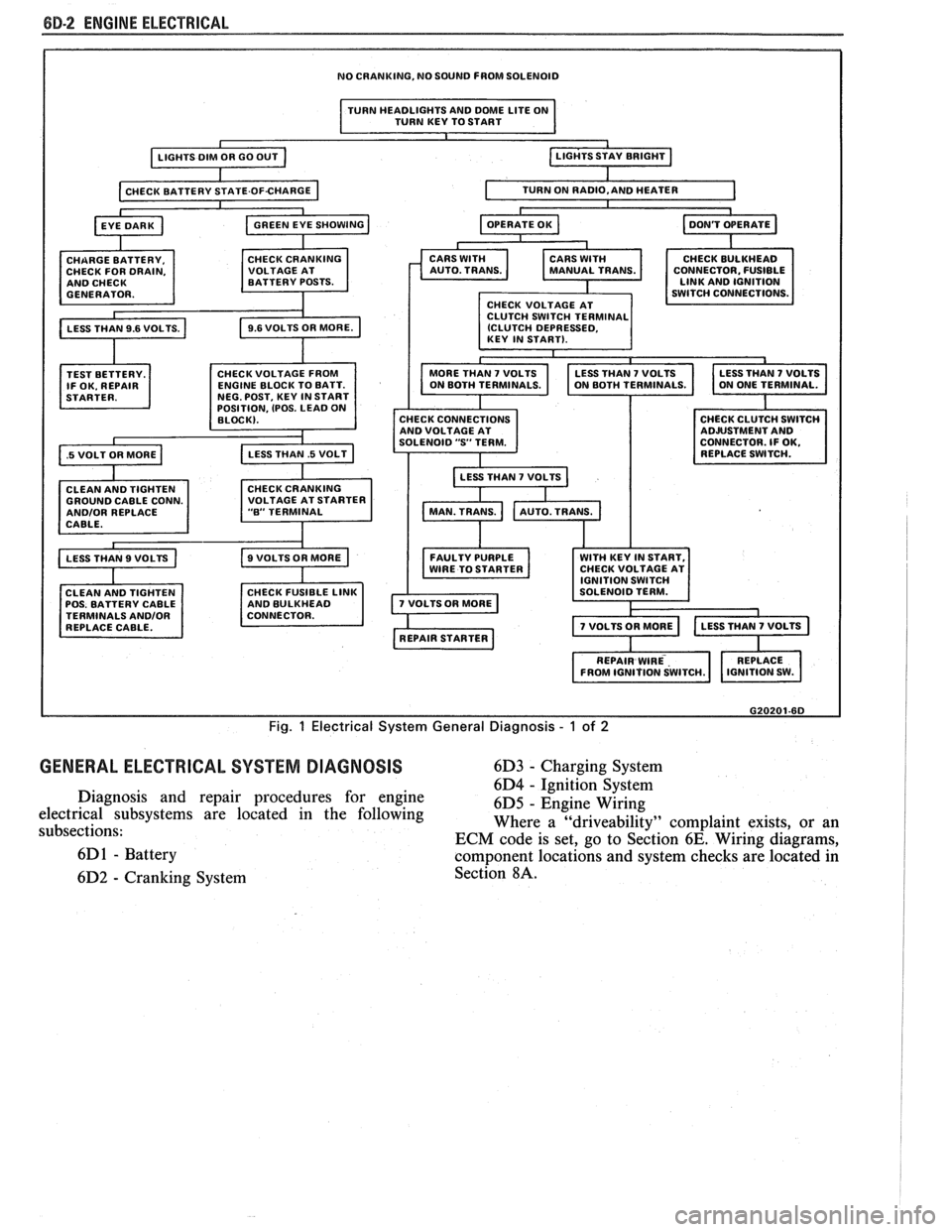
Fig. 1 Electrical System General Diagnosis - 1 of 2
GENERAL ELECTRICAL SYSTEM DIAGNOSIS 6D3 - Charging System
6D4
- ~~nitcon-§~stem Diagnosis and repair procedures for engine
6D5 - Engine Wiring
electrical subsystems are located in the following
subsections: Where a
"driveability" complaint
exists, or an
ECM code is set, go to Section
6E. Wiring diagrams,
6D
1 - Battery component locations and system checks are located in
6D2
- Cranking System Section 8A.
Page 486 of 1825
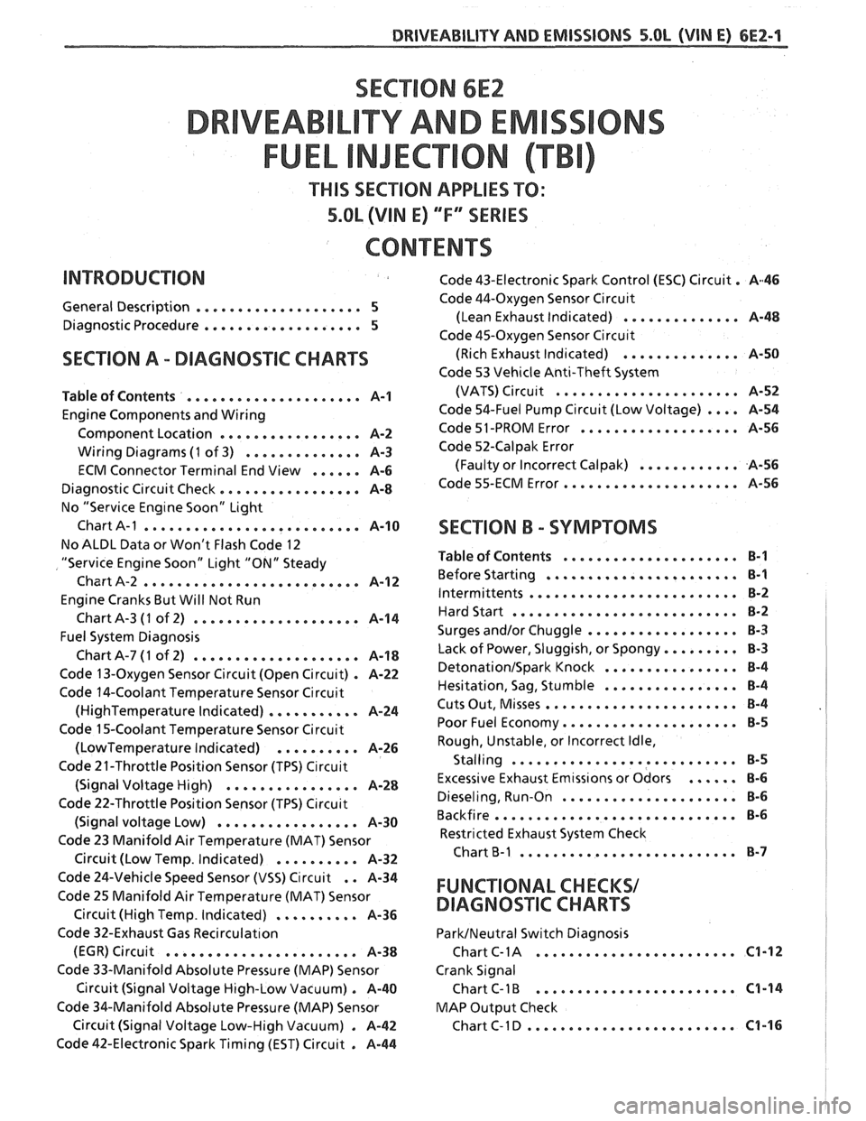
SECTION 6E2
TY AND EM
THIS SECTION APPLIES TO:
5.OL (VIN E) ""FYSERIES
CONTENTS
General Description .................... 5
Diagnostic Procedure ................... 5
SECTION A . DIAGNOSIIC CHARTS
Table of Contents ..................... A-1
Engine Components and Wiring
Component Location
................. A-2
Wiring Diagrams (1 of 3) .............. A-3
ECM Connector Terminal End View ...... A-6
Diagnostic Circuit Check ................. A-8
No "Service Eng~ne Soon" Light
Chart
A-1 .......................... A-10
No ALDL Data or Won't Flash Code 12
"Service Engine Soon" Light "ON" Steady
Chart A-2
.......................... A-1 2
Engine Cranks But Will Not Run
ChartA-3
(1 of 2) .................... A-14
Fuel System Diagnosis
ChartA-7(1 of 2) .................... A-18
Code 13-Oxygen Sensor Circuit (Open Circuit) . A-22
Code 14-Coolant Temperature Sensor Circuit
(HighTemperature Indicated) ........... A-24
Code 15-Coolant Temperature Sensor Circuit
(LowTemperature Indicated) .......... A-26
Code 21-Throttle Position Sensor (TPS) C~rcuit
(Signal Voltage High) ................ A-28
Code 22-Throttle Position Sensor (TPS) C~rcuit
(Signal voltage Low) ................. A-30
Code 23 Manifold Air Temperature (MAT) Sensor
. Circuit (Low Temp Indicated) .......... A-32
Code 43-Electronic Spark Control (ESC) Circuit . A46
Code 44-Oxygen Sensor Circu~t
(Lean Exhaust Indicated) .............. A-48
Code 45-Oxygen Sensor Circu~t
(Rich Exhaust Indicated) .............. A-50
Code 53 Vehicle Anti-Theft System
(VATS)
Circu~t ...................... A-52
Code 54-Fuel Pump Circuit (Low Voltage) .... A-54
Code 51 -PROM Error ................... A-56
Code 52-Calpak Error
(Faulty or Incorrect
Calpak) ............ A-56
Code 55-ECM Error ..................... A-56
SECTION B . SYMPTOMS
Table of Contents ..................... B-1
Before Starting ....................... B-1
Intermittents ......................... B-2
Hard Start ........................... 8-2
.................. Surges and/or Chuggle B-3
Lack of Power. Sluggish. or Spongy ......... 8-3
DetonationISpark Knock ................ 8-4
................ Hesitation. Sag. Stumble B-4
Cuts Out. Misses ....................... B-4
Poor Fuel Economy ..................... B-5
Rough. Unstable. or Incorrect Idle.
. Stalling ....................... ... B-5
Excessive Exhaust Emtss~ons or Odors ...... 8-6
Dieseling. Run-on ..................... 8-6
Backfire ............................. B-6
Restricted Exhaust System Check
Chart
B-1 .......................... 8-7
Code 24-Vehicle Speed Sensor (VSS) Circuit . . A-34
Code 25 Manifold Air Temperature (MAT) Sensor FUNCTIONAL CHECKS/
Circuit (High Temp . Indicated) .......... A-36 DIAGNOSqIC CHARTS
Code 32-Exhaust Gas Recirculat~on ParkINeutral Switch Diagnosis
........................ (EGR) Circuit ....................... A-38 Chart C- 1 A C1-12
Code 33-Manifold Absolute Pressure (MAP) Sensor Crank Signal
Circuit (Signal Voltage High-Low Vacuum)
. A-40 Chart C-1 B ........................ C1-14
Code %&Manifold Absolute Pressure (MAP) Sensor MAP
Output Check
......................... Circuit (Signal Voltage Low-High Vacuum) . A-42 ChartC-ID C1-16
Code 42-Electronic Spark Timing (EST) Circuit . A-44
Page 492 of 1825
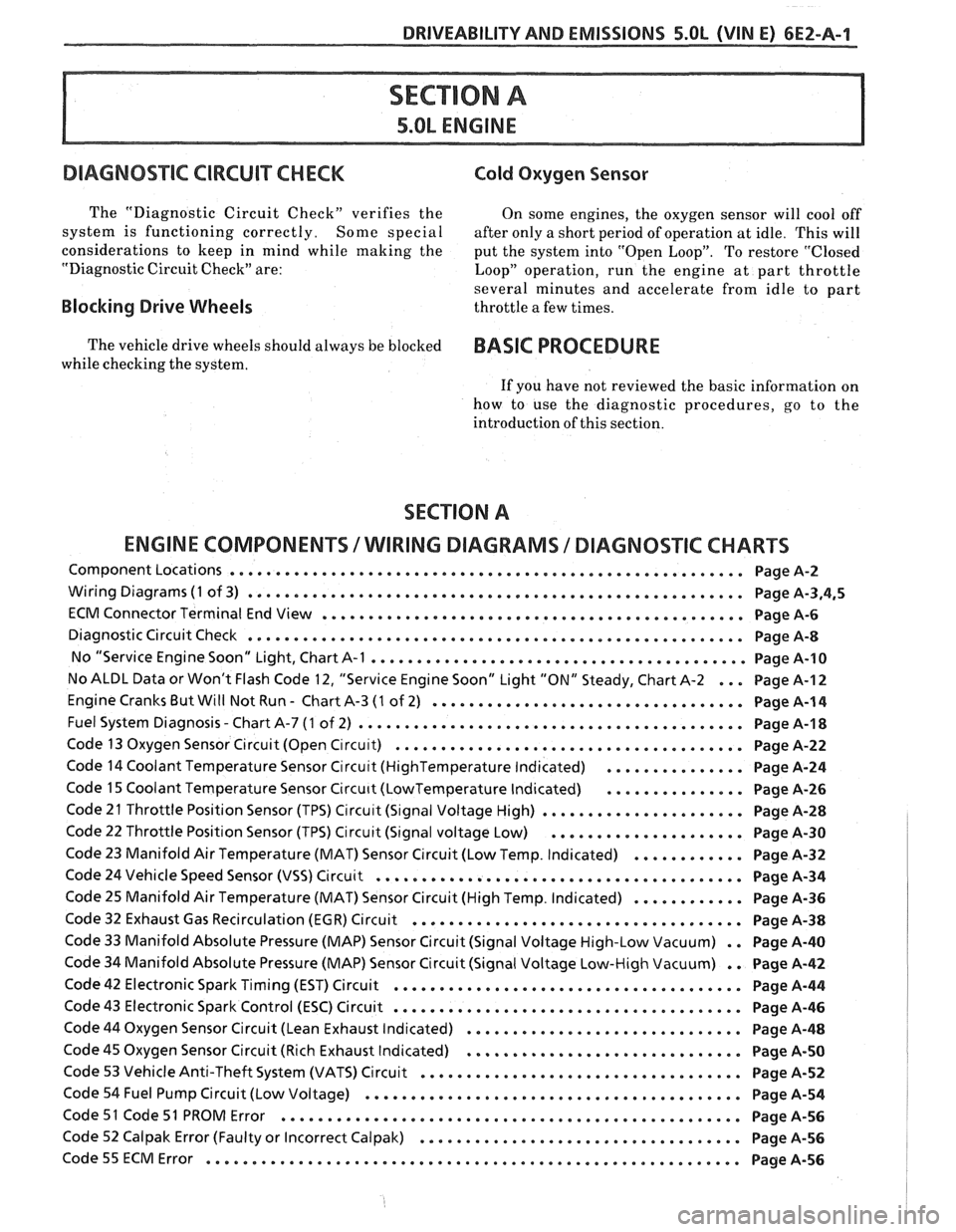
DRIVEABILITY AND EMISSIONS S.OL (VIN E) 6EZ-A-1
5.OL ENGINE
DIAGNOS"FC CIRCUIT CHECK Cold Oxygen Sensor
The "Diagnostic Circuit Check" verifies the On some engines. the oxygen sensor will cool off
system is functioning correctly
. Some special after only a short period of operation at idle . This will
considerations to keep in mind while making the
put the system into "Open Loop"
. To restore "Closed
"Diagnostic Circuit Check" are:
Loop" operation. run the engine at part throttle
several minutes and accelerate from idle to part
Blocking Drive Wheels throttle a few times .
The vehicle drive wheels should always be blocked BASIC PROCEDURE
while checking the system .
If you have not reviewed the basic information on
how to use the diagnostic procedures. go to the
introduction of this section
.
SECTION A
ENGINE COMPONENTS
/ WlRlNG DIAGRAMS 1 DIAGNOSTIC CHARTS
Component Locations ........................................................ Page A-2
Wiring Diagrams (1 of 3) ...................................................... Page A.3.4.5
ECM Connector Terminal End View .............................................. Page A-6
Diagnostic Circuit Check ...................................................... Page A-8
No "Service Engine Soon" Light. Chart A-1 ......................................... Page 14-10
No ALDL Data or Won't Flash Code 12. "Service Engine Soon" Light "ON" Steady. Chart A-2 ... Page A-I 2
Engine Cranks But Will Not Run . Chart A-3 (1 of 2) .................................. Page A-1 4
. Fuel System Diagnosis Chart A-7 (1 of 2) .......................................... Page A-1 8
Code 13 Oxygen Sensor Circuit (Open C~rcu~t) ...................................... Page A-22
Code 14 Coolant Temperature Sensor Circu~t (HighTemperature Indicated) ............... Page A-24
Code 15 Coolant Temperature Sensor Circu~t (LowTemperature Indicated) ............... Page A-26
Code 21 Throttle Position Sensor (TPS) Circu~t (S~gnal Voltage High) ...................... Page A-28
Code 22 Throttle Position Sensor (TPS) Circuit (Signal voltage Low) ..................... Page A-30
Code 23 Manifold Air Temperature (MAT) Sensor Circuit (Low Temp . Indicated) ............ Page A-32
Code 24 Vehicle Speed Sensor (VSS) Circuit ........................................ Page A-34
Code 25 Manifold Air Temperature (MAT) Sensor Circuit (High Temp . Indicated) ............ Page A-36
Code 32 Exhaust Gas Recirculation (EGR) Circuit .................................... Page A-38
Code 33 Manifold Absolute Pressure (MAP) Sensor Circuit (Signal Voltage High-Low Vacuum) . . Page A-40
Code 34 Manifold Absolute Pressure (MAP) Sensor Circuit (Signal Voltage Low-High Vacuum) . . Page A-42
Code 42 Electronic Spark Timing (EST) Circuit ...................................... Page A-44
Code 43 Electronic Spark Control (ESC) Circuit ...................................... Page A-46
Code 44 Oxygen Sensor Circuit (Lean Exhaust Indicated) .............................. Page A-48
Code 45 Oxygen Sensor Circuit (Rich Exhaust Indicated) .............................. Page A-50
Code 53 Vehicle Anti-Theft System (VATS) Circuit ................................... Page A-52
Code 54 Fuel Pump Circuit (Low Voltage) ......................................... Page A-54
Code 51 Code 51 PROM Error .................................................. Page A-56
Code 52 Calpak Error (Faulty or Incorrect Calpak) ................................... Page A-56
.......................................................... Code55ECMError PageA-56
Page 495 of 1825
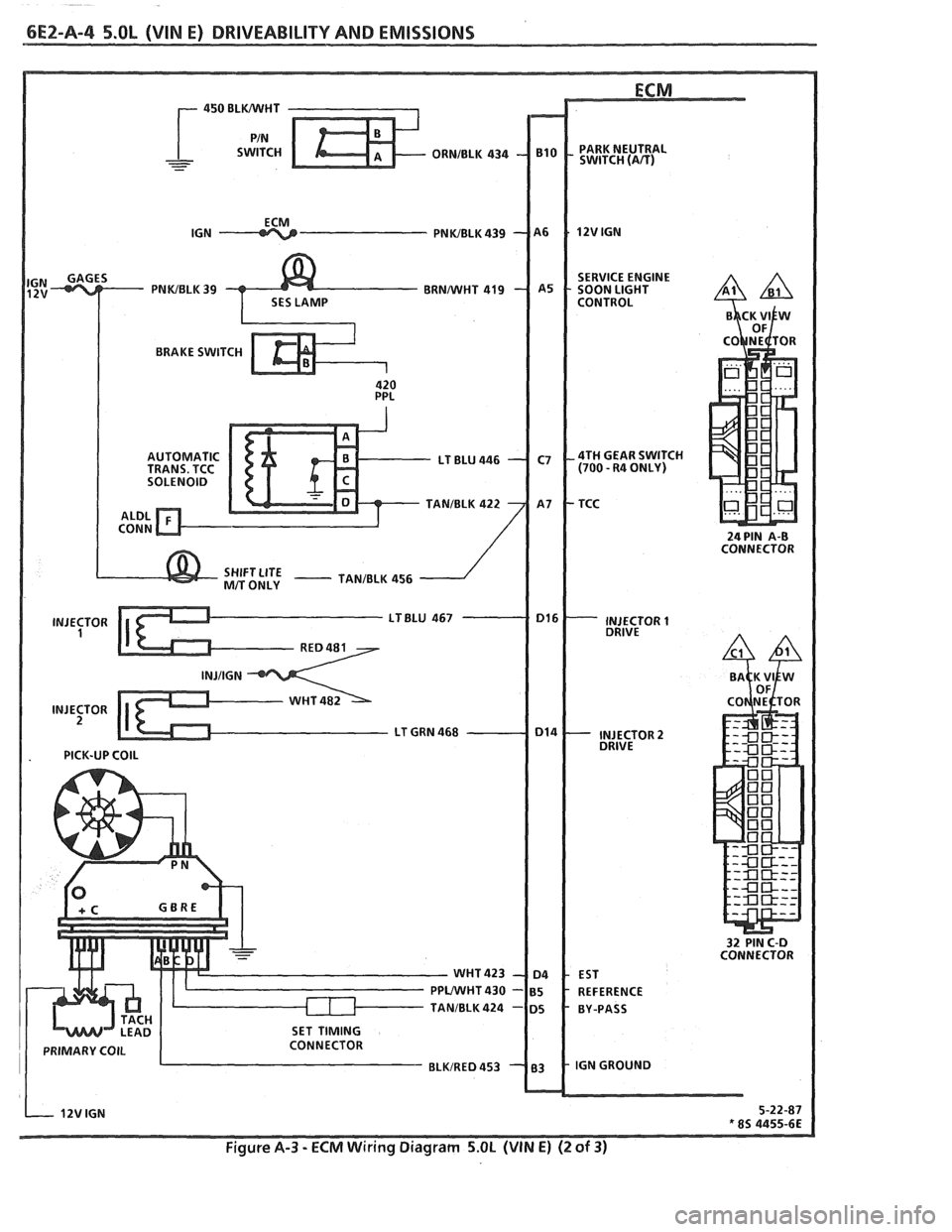
6E2-A-4 5.OL (VIN E) DRIVEABILITY AND EMISSIONS
SERVICE ENGINE
24PIN A-B CONNECTOR
SHIFTLITE __
* 8s 4455-6E - ~igure A-3 - ECM Wiring Diagram 5.OL (VIN E) (2 of 3)
Page 501 of 1825

6EZ-A-10 5.0L (VIN E) DRIVEABILITY AND EMISSIONS
TO OIL PRESS. SW.
&FUEL PUMP RELAY
BATTERY
12 V
. . . . . . . . FUSIBLE LINK 15 WAY
439 PNWBLK
419
BRNNVHT
SERIAL DATA
451
WHTIBLK
450 BLWHT
ALDL CONNECTOR
NO "SERVICE ENGINE SOON" "LIGHT
5.OL (VIN E) "F'" SERIES (TBI)
Circuit Description:
There should always be a steady "Service Engine Soon" light, when the ignition is "ON" and engine stopped.
Battery is supplied directly to the light bulb.
The electronic control module (ECM) will control the light and
turn it "ON" by providing a ground path through CKT 419 to the ECM.
Test Description: Numbers below refer to circled
numbers on the diagnostic chart.
1. Battery feed CKT 340 is protected by a
20amp in-
line fuse. If this fuse was blown, refer to wiring
diagram on the facing page of Code 54.
2. Using a test light connected to 12 volts, probe each
of the system ground circuits to be sure
a good
ground is present. See ECM terminal end view in
front of this section for ECM pin locations of
ground circuits.
Diagnostic Aids:
Engine runs ok, check:
@ Faulty light bulb
@ CKT419open
@ Gage fuse blown. This will result in no oil, or
generator lights, seat belt reminder, etc.
Engine cranks, but will not run.
@ Continuous battery - fuse or fusible link open.
@ ECM ignition fuse open.
@ Battery CKT 340 to ECM open.
o Ignition CKT 439 to ECM open.
@ Poor connection to ECM.