1988 PONTIAC FIERO degrees
[x] Cancel search: degreesPage 88 of 1825
R-4 AIR CONDITIONING COMPRESSOR OVERHAUL 1D1-9
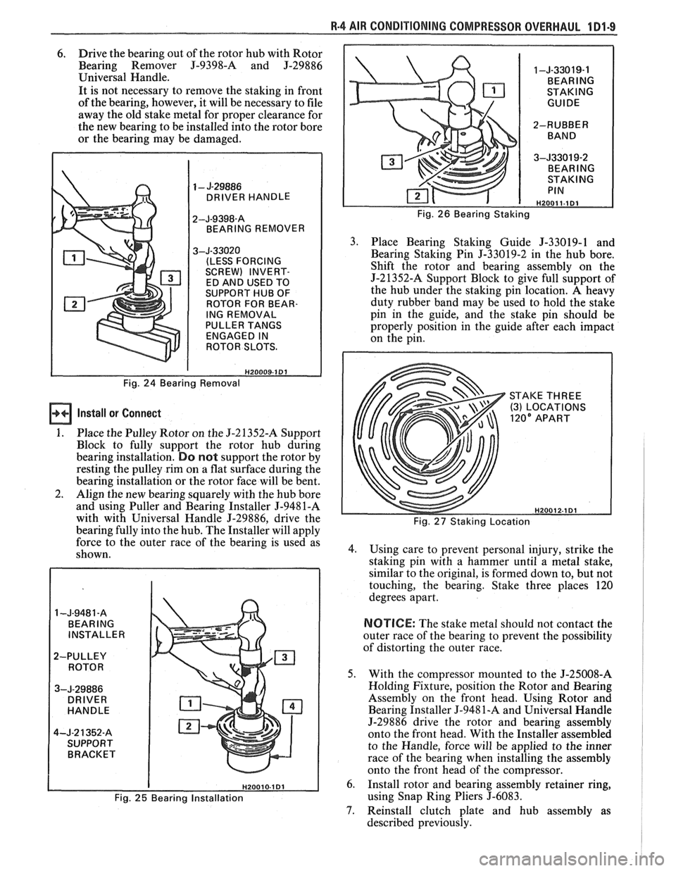
6. Drive the bearing out of the rotor hub with Rotor
Bearing Remover
J-9398-A and J-29886
Universal Handle.
It is not necessary to remove the staking in front
of the bearing, however, it will be necessary to file
away the old stake metal for proper clearance for
the new bearing to be installed into the rotor bore
or the bearing may be damaged.
DRIVER HANDLE
BEARING REMOVER
(LESS FORCING
SCREW) INVERT-
ED AND USED TO
SUPPORT HUB OF
ROTOR FOR BEAR-
ING REMOVAL
PULLER TANGS ENGAGED IN
ROTOR SLOTS.
Fig. 24 Bearing Removal
Install or Connect
1. Place the Pulley Rotor on the 5-2 1352-A Support
Block to fully support the rotor hub during
bearing installation.
Do not support the rotor by
resting the pulley rim on a flat surface during the
bearing installation or the rotor face will be bent.
2. Align the new bearing squarely with the hub bore
and using Puller and Bearing Installer
J-9481-A
with with Universal Handle 5-29886, drive the
bearing fully into the hub. The Installer will apply
force to the outer race of the bearing is used as
shown.
1 -J-9481 -A BEARING
INSTALLER
2-PULLEY ROTOR
3-J-29886 DRIVER
HANDLE
4-J-2
1352-8
SUPPORT BRACKET Fig.
26 Bearing Staking
3. Place Bearing Staking Guide J-33019-1 and
Bearing Staking Pin
5-33019-2 in the hub bore.
Shift the rotor and bearing assembly on the
J-21352-A Support Block to give full support of
the hub under the staking pin location. A heavy
duty rubber band may be used to hold the stake
pin in the guide, and the stake pin should be
properly position in the guide after each impact
on the pin.
STAKE THREE
(3) LOCATIONS
Fig. 27 Staking Location
4. Using care to prevent personal injury, strike the
staking pin with a hammer until a metal stake,
similar to the original, is formed down to, but not
touching, the bearing. Stake three places
120
degrees apart.
NOTICE: The stake metal should not contact the
outer race of the bearing to prevent the possibility
of distorting the outer race.
5. With the compressor mounted to the J-25008-A
Holding Fixture, position the Rotor and Bearing
Assembly on the front head. Using Rotor and
Bearing Installer
5-948 1-A and Universal Handle
J-29886 drive the rotor and bearing assembly
onto the front head. With the Installer assembled
to the Handle, force will be applied to the inner
race of the bearing when installing the assembly
onto the front head of the compressor.
6. Install rotor and bearing assembly retainer ring,
Fig. 25 Bearing Installation using Snap Ring Pliers J-6083.
7. Reinstall clutch plate and hub assembly as
described previously.
Page 138 of 1825
STEERING, SUSPENSION, TIRES AND WHEELS DIAGNOSIS 3.13
in doubt about the condition, compare with a
shock known to be good.
Noisy
For struts, follow Steps 1 through 3.
1. Check all mountings for proper torque. A loose
mounting will cause a noise.
2. If all mountings are intact, bounce the car as in
Step
4 (weak) to isolate the suspected unit.
3. If practical, ride with the owner to be sure you
understand the complaint, before proceeding to
next step.
4. If one of the rear shocks is noisy, the rear axle
should be supported at least enough to unload the
shock mounts. Disconnect the lower mounting of
the suspected shock. Quickly push the shock all
the way in, then all the way out.
A hissing noise
is normal.
5. Other objectionable noises may be detected by
stroking. Any sound other
than hissing is
abnormal; replace the shock.
Leaks
1. Fully extend the strut/shocks (wheels
unsupported) to expose the seal cover area for
inspection.
2. Look for
signs of leaks in the seal cover area.
3. A slight trace of fluid is NOT cause for
replacement; the seal permits some seepage to
lubricate the piston rod. There is a built in fluid
reserve to allow for seepage.
4. A leaking strut dampener/shock can easily be
found because there will be fluid around the seal
cover and an excessive amount of fluid on the
strut
dampener/shock. A leaking strut
dampener/shock must be replaced.
BENCH CHECKS
Strut Dampeners and Regular Shock Absorbers
(Standard and Firm Ride)
Regular strut dampenerdrear shocks use a
gas-filled cell in the fluid reservoir. Aeration or
foaming of the fluid is eliminated, as the gas and the
fluid cannot mix.
Proceed with the actual bench check as follows:
1. Clamp the strut dampener/shock UPSIDE
DOWN in the vise. Do not clamp on the reservoir
tube or the mounting threads. If a lag is noticed
when it is stroked, it means the gas-filled cell has
ruptured and replacement is necessary.
2. Pump strut dampener/shock by hand at various
rates of speed and note the resistance.
3. Rebound resistance normally is stronger than
compression resistance by about 2 to 1. However,
the resistance should be smooth and constant for
each stroking rate.
4. Compare with a strut dampener/ shock known to
be good.
5. It is normal to hear a hissing noise. The following
symptoms are abnormal and are reason for
replacement. A.
A skip or lag at reversal near mid-stroke.
B. A seize (except at either extreme end of
travel).
C. A noise (such as a grunt or squeal) after
completing one full stroke in both
directions.
D. A clicking noise at fast reversal.
E. Fluid leakage.
TIRE DIAGNOSIS
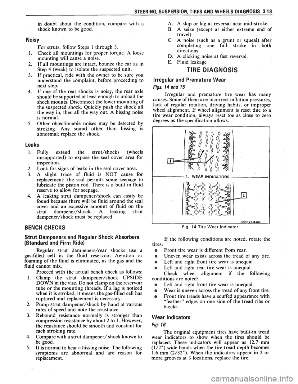
Irregular and Premature Wear
Figs. 14 and 15
Irregular and premature tire wear has many
causes. Some of them are: incorrect inflation pressures,
lack of regular rotation, driving habits, or improper
wheel alignment. If wheel alignment is reset due to a
tire wear condition, always reset toe as close to zero
degrees as the specification allows.
1. WEAR INDICATORS I
Fig. 14 Tire Wear Indicator
If the following conditions are noted, rotate the
tires:
@ Front tire wear is different from rear.
Uneven wear exists across the tread of any tire.
e Left and right front tire wear is unequal.
Left and right rear tire wear is unequal.
Check wheel alignment if the following
conditions are noted:
e Left and right front tire wear is unequal.
Wear is uneven across the tread of any front tire.
e Front tire treads have a scuffed appearance with
"feather" edges on one side of the tread ribs or
blocks.
Wear Indicators
Fig. 16
The original equipment tires have built-in tread
wear indicators to show when the tires should be
replaced. These indicators will appear as 12.7 mm
(1/2") wide bands when the tire tread depth becomes
1.6 mm (2/32"). When the indicators appear in 2 or
more grooves at
3 locations, replace the tire.
Page 148 of 1825
-
WHEEL. ALIGNMENT 3A-1
SECTION 3A
WHEEL AL GNMENT
NOTICE: These fasteners are important attaching Do not use a replacement part of lesser quality or
parts, in that they could affect the performance of substitute
design. Torque values must be used as
vital components and systems, and/or could result specified during reassembly to assure proper
in major repair expense. They must be replaced retention of these parts. For prevailing torque
with one of the same part number or with an
nut(s) and bolt(s), refer to the "Reuse of Prevailing
equivalent part if replacement becomes necessary. torque
Nut(s) and Bolt(s)" chart in Section 0.
General Description ...................... .. ...... 3A- 1 On-Car Service ........................ .. ........... 3A-2
Caster .................... .. ............................ 3A- 1 Caster and Camber Adjustment .................. 3A-2
..................................... Camber ................... .. .............................. 3A-I Toe-In Adjustment 3A-2
Toe.. ................................................. 3A- 1 Axle Housing Alignment ......................... .... 3A-4
Preliminary Checks Prior to Specifications ....................... ... ............... 3A-4
Adjusting Alignment ..................... ...... 3A- 1
GENERAL DESCRIPmIOMI
Wheel alignment refers to the angular they tend to roll parallel on the road when the car is
relationship between the wheels, the suspension moving.
attaching parts and the ground.
PRELIMINARY CHECKS PRIOR TO ADJUSTING
CASTER ALIGNMENT
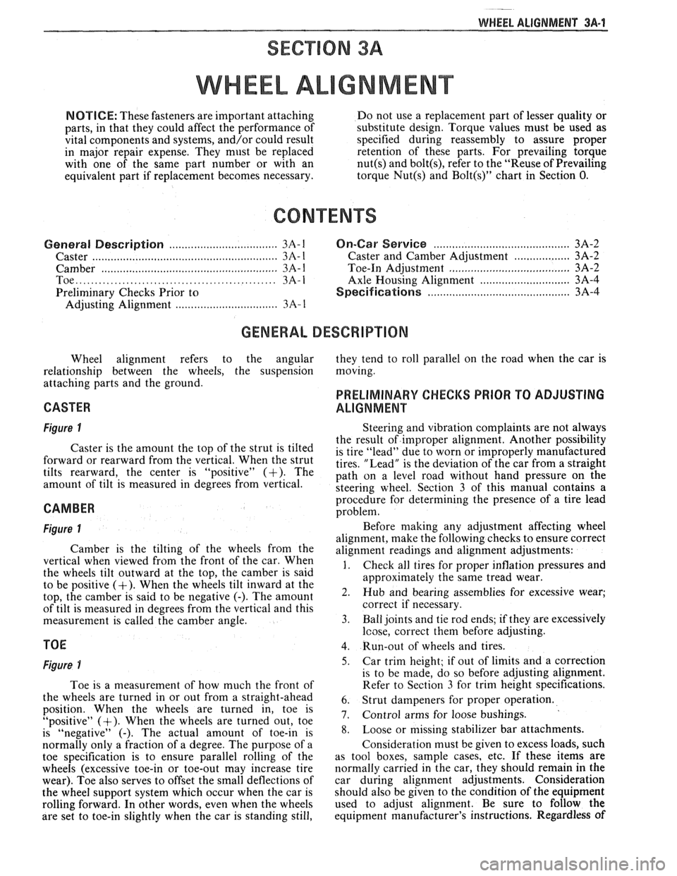
Figure 1
Caster is the amount the top of the strut is tilted
forward or rearward from the vertical. When the strut
tilts rearward, the center is "positive"
(+). The
amount of tilt is measured in degrees from vertical.
CAMBER
Figure 1
Camber is the tilting of the wheels from the
vertical when viewed from the front of the car. When
the wheels tilt outward at the top, the camber is said
to be positive
(+). When the wheels tilt inward at the
top, the camber is said to be negative
(-). The amount
of tilt is measured in degrees from the vertical and this
measurement is called the camber angle.
TOE
Figure i
Toe is a measurement of how much the front of
the wheels are turned in or out from a straight-ahead
position. When the wheels are turned in, toe is
"positive"
(+). When the wheels are turned out, toe
is "negative"
(-). The actual amount of toe-in is
normally only a fraction of a degree. The purpose of a
toe specification is to ensure parallel rolling of the
wheels (excessive toe-in or toe-out may increase tire
wear). Toe also serves to offset the small deflections of
the wheel support system which occur when the car is
rolling forward. In other words, even when the wheels
are set to toe-in slightly when the car is standing still, Steering
and vibration complaints are not always
the result of improper alignment. Another possibility
is tire "lead" due to worn or improperly manufactured
tires. "Lead" is the deviation of the car from a straight
path on a level road without hand pressure on the
steering wheel. Section
3 of this manual contains a
procedure for determining the presence of a tire lead
problem.
Before making any adjustment affecting wheel
alignment, make the following checks to ensure correct
alignment readings and alignment adjustments:
1. Check all tires for proper inflation pressures and
approximately the same tread wear.
2. Hub and bearing assemblies for excessive wear;
correct if necessary.
3. Ball joints and tie rod ends; if they are excessively
lcose, correct them before adjusting.
4. Run-out of wheels and tires.
5. Car trim height; if out of limits and a correction
is to be made, do so before adjusting alignment.
Refer to Section
3 for trim height specifications.
6. Strut dampeners for proper operation.
7. Control arms for loose bushings.
8. Loose or missing stabilizer bar attachments.
Consideration must be given to excess loads, such
as tool boxes, sample cases, etc. If these items are
normally carried in the car, they should remain in the
car during alignment adjustments. Consideration
should also be given to the condition of the equipment
used to adjust alignment. Be sure to follow the
equipment manufacturer's instructions. Regardless
of
Page 240 of 1825
TIRES AND WHEELS 3E-9
Another method is to dismount the tire and
rotate it 180 degrees on the rim. It is important that
this be done on tire and wheel assemblies which are
known to be causing a vibration as it is just as likely to
cause good assemblies to vibrate.
Refer to Section 3, "Vibration Diagnosis" for
more details.
ALUMINUM WHEEL CLEANING
Aluminum wheels should be cleaned and waxed
regularly. Do not use abrasive cleaners, as they could
damage the protective coating.
ALUMINUM WHEEL HUB CAP
Remove or Disconnect
1. Tire and wheel assembly
2. Place a block of wood approximately 2" in
diameter with a squared off end against the back
surface of the cap.
A sharp hammer biow on the
block of wood will
remove the cap.
Install or Connect
1. Place
cap into position at wheel opening and
place a block of wood at least three inches in
diameter against cap face. Install cap by striking
block of wood with hammer.
2. Tire and wheel assembly
NOTICE: Failure to hit cap squarely without the
load distributed evenly could result in permanent
damage to the cap.
ALUMINUM WHEEL POROSITY REPAIR
1. Remove tire and wheel assembly.
2. Locate
leaking areas by inflating tire to 345
kPa
(50 psi) and dipping tire and wheel assembly into
a water bath.
3. Mark
leak areas and remove tire from wheel.
4. Scuff inside surface at leak area with 80 grit
sandpaper and clean area with general purpose
cleaner such as
3M #08984 or equivalent.
5. Apply 1/8" thick layer of adhesive/sealant P/N
1052366 or equivalent to leak area and allow
twelve hours of drying time.
6. Mount tire on wheel, pressurize to 345 kPa (50
psi) and check for leaks.
CAUTION: To avoid serious personal
injury, do not stand over tire when
inflating. Bead may break when bead
snaps over safety hump. Do not
exceed
275 kPa (40 psi) pressure
when inflating any tire if beads are
not seated.
14 275 kPa (40 psi)
pressure will not seat beads, deflate,
relubricate the beads and reinflate.
Overinflation may cause the bead to
break and cause serious personal
injury.
7. Adjust
tire pressure to meet specifications.
8. Balance tire and wheel assembly.
9. Install tire and wheel assembly.
ALUMINUM WHEEL REFINISHING
A protective clear or color coating is applied to
the surface of original equipment cast aluminum
wheels.
A surface degradation condition can begin to
develop if frequent, repeated automatic car wash
cleaning abrades or wears off the factory applied
protective coating. This can happen at some automatic
car wash facilities using aggressive silicon carbide
tipped tire brushes
to clean white walls and tires. Once
the protective coating is
damaged, exposure to caustic
cleaners and/or road salt further causes surface
degradation. The following procedure details how to
strip, clean
and recoat aluminum wheels that are
affected by these conditions.
Required Materials:
A~nchern Alumi Prep #33 - stock
#DX533 or equivalent - cleaning and
conditioning chemical for aluminum.
Amchem Alodine
# 1001 - stock #DXSOT
or equivalent - coating chemical for
aluminum.
Ditzler Delclear Acrylic Urethane Clear
-
stock #DAU-75 or equivalent.
Ditzler Delthane Ultra-Urethane Additive
- stock DXR-80 or equivalent.
Service Procedure:
1. Mark wheel and wheel stud for position on car.
2. Remove tire and wheel assembly from car.
3. Mark location of outboard weights and remove.
4. Wash wheel inside and out with water base all
purpose cleaner. Remove grease and oil with
solvent cleaner.
5. Mask off tire prior to painting.
6. Select and follow the correct procedure,
"Aluminum Damage on Wheel Surface" or
"Clear Coat Damage on Unpainted Wheels".
7. Replace wheel weights with nylon coated
weights.
8. Install tire and wheel assembly on car and tighten
wheel nuts to proper torque.
Accent Color Preparation
1. Sand over painted areas that will not require
recoloring with 400 grit (wet or dry) to promote
adhesion of clear coat.
Aluminum Damage on Wheel Surface
1. Mount tire and wheel on brake lathe and spin
slowly.
2. Sand wheel with backing block or pad by holding
abrasive flat to surface of wheel and moving
slowly back and forth from center to outer edge
to remove damage. Use the following sandpaper
grits in the order listed.
A. Sand with 80 grit
B. Sand with 150 grit
C. Sand with 240 grit
3. Continue with "Recoating Procedure."
Page 244 of 1825
PROPELLER SHAFT $A-3
B. If companion flange run-out is over 0.15mm (.006
in.) but less than 0.28mm (.011 in.) and balance
weight is at or near low point of companion flange
run-out, no further action is required.
If balance weight is not at or near low point of
companion flange run-out, remove weight.
6. If companion flange run-out is over 0.28mm (.011
in.), but no greater than 0.38mm (.015 in.) and
balance weight is at or near low point of
companion flange run-out, no further action is
required.
If balance weight is not at or near low point of
companion flange
runout, remove weight and
reindex companion flange until run-out is 0.25
mm
(.010 in.) or less.
If impossible to achieve
0.25mm (.010 in.) or less
run-out, install a new companion flange and
recheck for
0.25mm (.010 in.) or less run-out.
Service replacement companion flanges are not
equipped with balance weights and no weights
should be added.
UNIVERSAL JOINT ANGLE MEASUREMENT
When torque is transmitted through any ordinary
universal joint, the driven yoke fluctuates slightly in
speed. In other words, although the driving yoke
rotates at a constant speed, the driven yoke speeds up
and slows down twice per revolution. This flucutation
of the driven yoke is in direct proportion to the angle
through which the universal joint is operating; the
greater the angle, the greater the fluctuation.
Whenever two universal joints are used, this
fluctuation effect can be eliminated by staggering the
joints so that the two driving yokes are 90 degrees apart
provided the two joints are transmitting torque
through the same angle.
Therefore, when two universal joints are used, the
angles through which they operate must be very nearly the
same. This allows the alternate acceleration and decelera-
tion of one joint to be offset by the alternate acceleration
and deceleration of the second joint. When the two joints
do not run at approximately the same angle, operation is
rough and an objectionable vibration is produced.
The actual optimum angles desired must take into
consideration the effects of various passenger loadings
and rear axle windup during acceleration; therefore, it
is unlikely that the front and rear universal joint angles
will be found to be the same in actual practice.
In addition, universal joints are designed to
operate safely and efficiently within certain angles. If
the designed angle is exceeded, the joint may be broken
or otherwise damaged.
The front universal joint angle is actually the
angle between the engine-transmission centerline and
the propeller shaft centerline. This angle is determined
by the design of the frame assembly and may be altered
by adding or removing shims between the transmission
and the transmission mount.
Adding one shim at the transmission mount will
decrease the transmission universal joint angle by
1/2"
and increase differential universal joint angle by 1/4".
If one shim is removed the tranmission angle will
increase
1/2" and decrease differential angle I/@. The
production transmission mount bolt is an
M10-1.5 x 35
mm. When installing two or more shims, an
M10-1.5
x 50 mm bolt must be used.
All complaints of propeller shaft vibrations
should be accompanied by rear trim height
measurements at curb weight. An incorrect trim height
may cause some vibration. If vibration is severe
enough, removal or installation of spring shims may be
required. If any irregular roughness or vibration is
detectable in the drive line, the front and rear universal
joint angles should be checked. Should the vehicle
become involved in a severe rear end collision, or
should the rear axle carrier be replaced, the rear
universal joint angle should be checked and control
arms should be replaced if necessary.
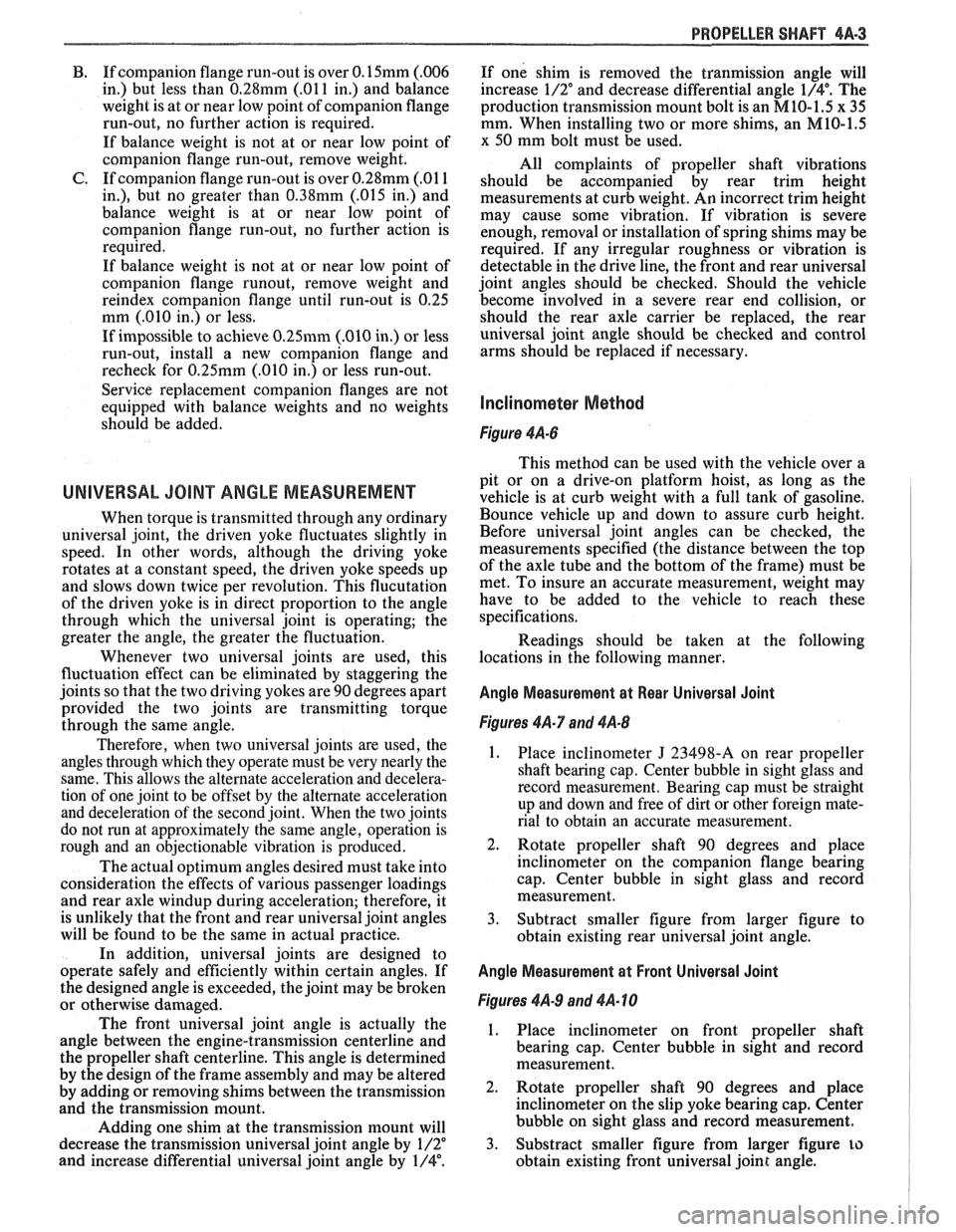
Figure 4A-6
This method can be used with the vehicle over a
pit or on a drive-on platform hoist, as long as the
vehicle is at curb weight with a full tank of gasoline.
Bounce vehicle up and down to assure curb height.
Before universal joint angles can be checked, the
measurements specified (the distance between the top
of the axle tube and the bottom of the frame) must be
met. To insure an accurate measurement, weight may
have to be added to the vehicle to reach these
specifications.
Readings should be taken at the following
locations in the following manner.
Angle Measurement at Rear Universal Joint
Figures 4A-7 and 4A-8
1. Place inclinometer J 23498-A on rear propeller
shaft bearing cap. Center bubble in sight glass and
record measurement. Bearing cap must be straight
up and down and free of dirt or other foreign mate-
rial to obtain an accurate measurement.
2. Rotate propeller shaft 90 degrees and place
inclinometer on the companion flange bearing
cap. Center bubble in sight glass and record
measurement.
3. Subtract smaller figure from larger figure to
obtain existing rear universal joint angle.
Angle Measurement at Front Universal Joint
Figures 4A.9 and 4A- 10
1. Place inclinometer on front propeller shaft
bearing cap. Center bubble in sight and record
measurement.
2. Rotate propeller shaft 90 degrees and place
inclinometer on the slip yoke bearing cap. Center
bubble on sight glass and record measurement.
3. Substract smaller figure from larger figure
lo
obtain existing front universal joint angle.
Page 245 of 1825
4A-4 PROPELLER SHAFT
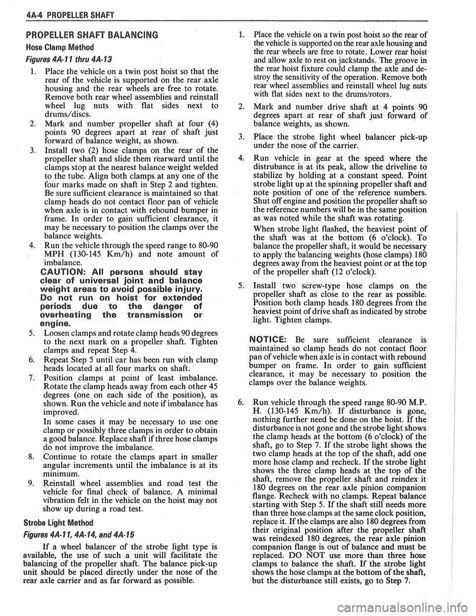
PROPELLER SHAFT BALANCING
Hose Clamp Method
Figures 4A- 1 1 thru 4A-13
1. Place the vehicle on a twin post hoist so that the
rear of the vehicle is supported on the rear axle
housing and the rear wheels are free to rotate.
Remove both rear wheel assemblies and reinstall
wheel lug nuts with flat sides next to
drums/discs.
2. Mark and number propeller shaft at four (4)
points 90 degrees apart at rear of shaft just
forward of balance weight, as shown.
3. Install two (2) hose clamps on the rear of the
propeller shaft and slide them rearward until the
clamps stop at the nearest balance weight welded
to the tube. Align both clamps at any one of the
four marks made on shaft in Step 2 and tighten.
Be sure sufficient clearance is maintained so that
clamp heads do not contact floor pan of vehicle
when axle is in contact with rebound bumper in
frame. In order to gain sufficient clearance, it
may be necessary to position the clamps over the
balance weights.
4. Run the vehicle through the speed range to 80-90
MPH (130-145
Km/h) and note amount of
imbalance.
CAUTION: All persons should stay
clear of universal joint and balance
weight areas to avoid possible injury.
Do not run on hoist for extended
periods due to the danger of
overheating the transmission or
engine.
5. Loosen clamps and rotate clamp heads 90 degrees
to the next mark on a propeller shaft. Tighten
clamps and repeat Step 4.
6. Repeat Step 5 until car has been run with clamp
heads located at all four marks on shaft.
7. Position clamps at point of least imbalance.
Rotate the clamp heads away from each other 45
degrees (one on each side of the position), as
shown. Run the vehicle and note if imbalance has
improved.
In some cases it may be necessary to use one
clamp or possibly three clamps in order to obtain
a good balance. Replace shaft if three hose clamps
do not improve the imbalance.
8. Continue to rotate the clamps apart in smaller
angular increments until the imbalance is at its
minimum.
9. Reinstall wheel assemblies and road test the
vehicle for final check of balance. A minimal
vibration felt in the vehicle on the hoist may not
show up during a road test.
Strobe Light Method
Figures 461- 1 1, $A- 14, and 4A- 15
If a wheel balancer of the strobe light type is
available, the use of such a unit will facilitate the
balancing of the propeller shaft. The balance pick-up
unit should be placed directly under the nose of the
rear axle carrier and as far forward as possible. 1.
Place
the vehicle on a twin post hoist so the rear of
the vehicle is supported on the rear axle housing and
the rear wheels are free to rotate. Lower rear hoist
and allow axle to rest on jackstands. The groove in
the rear hoist fixture could clamp the axle and de-
stroy the sensitivity of the operation. Remove both
rear wheel assemblies and reinstall wheel lug nuts
with flat sides next to the
drums/rotors.
2.
Mark and number drive shaft at 4 points 90
degrees apart at rear of shaft just forward of
balance weights, as shown.
3. Place the strobe light wheel balancer pick-up
under the nose of the carrier.
4. Run vehicle in gear at the speed where the
distrubance is at its peak, allow the driveline to
stabilize by holding at a constant speed. Point
strobe light up at the spinning propeller shaft and
note position of one of the reference numbers.
Shut off engine and position the propeller shaft so
the reference numbers will be in the same position
as was noted while the shaft was rotating.
When strobe light flashed, the heaviest point of
the shaft was at the bottom (6 o'clock). To
balance the propeller shaft, it would be necessary
to apply the balancing weights (hose clamps) 180
degrees away from the heaviest point or at the top
of the propeller shaft (12 o'clock).
5. Install two screw-type hose clamps on the
propeller shaft as close to the rear as possible.
Position both clamp heads 180 degrees from the
heaviest point of drive shaft as indicated by strobe
light. Tighten clamps.
NOTICE: Be sure sufficient clearance is
maintained so clamp heads do not contact floor
pan of vehicle when axle is in contact with rebound
bumper on frame. In order to gain. sufficient
clearance, it may be necessary to position the
clamps over the balance weights.
6. Run vehicle through the speed range 80-90
M.P.
H. (130-145 Km/h). If disturbance is gone,
nothing further need be done on the hoist. If the
disturbance is not gone and the strobe light shows
the clamp heads at the bottom (6 o'clock) of the
shaft, go to Step
7. If the strobe light shows the
two clamp heads at the top of the shaft, add one
more hose clamp and recheck. If the strobe light
shows the three clamp heads at the top of the
shaft, remove the propeller shaft and
reindex it
180 degrees on the rear axle pinion companion
flange. Recheck with no clamps. Repeat balance
starting with Step 5. If the shaft still needs more
than three hose clamps at the same clock position,
replace it. If the clamps are also 180 degrees from
their original position after the propeller shaft
was reindexed 180 degrees, the rear axle pinion
companion flange is out of balance and must be
replaced. DO NOT use more than three hose
clamps to balance the shaft. If the strobe light
shows the hose clamps at the bottom of the shaft,
but the disturbance still exists, go to Step
7.
Page 338 of 1825
POWER HEAD ASSEMBLY 5D2-3
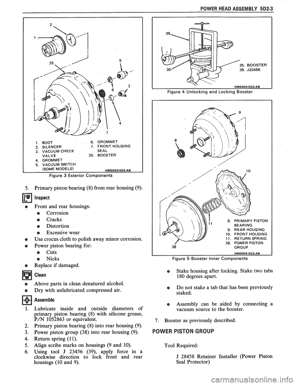
1. BOOT 6. GROMMET 2. SILENCER 7. FRONT HOUSING 3. VACUUM CHECK SEAL VALVE 35. BOOSTER
Figure 3 Exterior Components
5. Primary piston bearing (8) from rear housing (9).
Inspect
e Front and rear housings:
e Corrosion
e Cracks
e Distortion
e Excessive wear
e Use crocus cloth to polish away minor corrosion.
e Power piston bearing for:
e Cuts
e Nicks
e Replace if damaged.
Clean
e Above parts in clean denatured alcohol.
e Dry with unlubricated compressed air.
Assemble
1. Lubricate inside and outside diameters of
primary piston bearing (8) with silicone grease,
P/N 1052863 or equivalent.
2. Primary piston bearing (8) into rear housing (9).
3. Power piston group (38) into rear housing (9).
4. Return spring (1 1).
5. Align scribe marks on housings (9 and 10).
6. Using tool
J 23456 (39), apply force in a
clockwise direction to lock front and rear
housings (10 and 9).
8. PRIMARY PISTON BEARING 9. REAR HOUSING 10. FRONT HOUSING 11. RETURN SPRING 38. POWER PISTON
Figure 5 Booster Inner Components
e Stake housing after locking. Stake two tabs
180 degrees apart.
e Do not stake a tab that has been previously
staked.
e Assembly can be aided by connecting a
vacuum source to the booster.
7. Booster as previously described.
POWER PISTON GROUP
Tool Required:
J 28458 Retainer Installer (Power Piston
Seal Protector)
Page 374 of 1825
2.8 LITER V-6 8A2-23
4. Make sure the gap in the oil ring rails are in "up"
position toward center of engine and the gaps of
the compression rings are positioned as shown in
Figure
6A2-30.
5. Install each connecting rod and piston assembly
in its respective bore. Install with connecting rod
bearing tang slots on side opposite camshaft. Use
Tool J-8037 or J-8910 to compress the rings.
Guide the connecting rod into place on the
crankshaft journal.
Use a hammer handle and light blows to install
the piston into the bore. Hold the ring
compressor firmly against the cylinder block
until all piston rings have entered the cylinder
bore.
6. Install the bearing caps and torque nuts to
specifications. If bearing replacement is required
refer to "Connecting Rod Bearings".
Be sure to install new pistons in the same
cylinders for which they were fitted, and used
pistons in the same cylinder from which they
were removed. Each connecting rod and bearing
cap should be marked, beginning at the front of
the engine.
On V-6 engines, 1,3 and 5 are in the right bank
and 2,
4 and 6 are in the left bank. The numbers
on the connecting rod and bearing cap must be on
the same side when installed in the cylinder bore.
If a connecting rod is ever transposed from one
block or cylinder to another, new bearings should
be fitted and the connecting rod should be
numbered to correspond with the new cylinder
number.
NOTE. All dlrnenslons are In rn~ll~rnetres.
Figure 6A2-3 1 Service Pistons
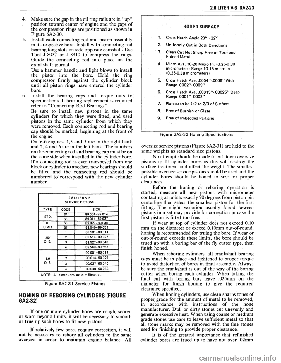
HONING OR REBORING CYLINDERS (FIGURE
6A2-32)
If one or more cylinder bores are rough, scored
or worn beyond limits, it will be necessary to smooth
or true up such bores to fit new pistons.
If relatively few bores require correction, it will
not be necessary to
rebore all cylinders to the same
oversize in order to maintain engine balance. All
HONED SURFACE
1.
Cross Hatch Angle 20' - 32'
2.
Uniformly Cut in Both Directions
3. Clean Cut Not Sharp Free of Torn and
Folded Metal
4. Micro Ave. 10-20 Micro In. (0.254.30 micrometers) Range 10-1 5 micro in.
(0.25-0.38 micrometers)
5. Cross Hatch Ave.
.0004"-.0006" Wide
Range ,0002"-.0009"
6. Cross Hatch Ave. ,0001 5"-.00025" Deep Ranw ,0081 "-.0003"
7. Plateau to be 1/2 to 2/3 of Surface
8. Free of Burnish or Glaze
I 9. Free of Imbedded Particles I
I I Figure 6A2-32 Honing Specifications
oversize service pistons (Figure 6A2-3 1) are held to the
same weights as standard size pistons.
No attempt should be made to cut down oversize
pistons to fit cylinder bores as this will destroy the
surface treatment and affect the weight. The smallest
possible oversize service pistons should be used and the
cylinder bores should be honed to size for proper
clearances.
Before the honing or
reboring operation is
started, measure all new pistons with micrometer
contacting at points exactly 90 degrees from piston pin
centerline then select the smallest piston for the first
fitting. The slight variation usually found
beween
pistons in a set may provide for correction in case the
first piston is fitted too free.
If wear at top of cylinder does not exceed 0.10
mm on the diameter or exceed
0.lOmm out-of-round,
honing is recommended for truing the bore. If wear or
out-of-round exceeds these limits, the bore should be
trued up with a boring bar of the fly cutter type, then
finish honed.
When
reboring cylinders, all crankshaft bearing
caps must be in place and tightened to proper torque
to avoid distortion of bores in final assembly. Always
be sure the crankshaft is out of the way of the boring
cutter when boring each cylinder. When taking the
final cut with boring bar, leave
,025mm on the
diameter for finish honing to give the required
clearance specified.
When honing cylinders, use clean sharps tones of
proper grade for the amount of metal to be removed,
in accordance with instructions of the hone
manufacturer. Dull or dirty stones cut unevenly and
generate excessive heat. When using coarse or medium
grade stones use care to leave sufficient metal so that
all stone marks may be removed with the fine stones
used for finishing to provide proper clearance.
It is of the greatest importance that refinished
cylinder bores are trued up to have not over
.02mm