1988 PONTIAC FIERO headlamp
[x] Cancel search: headlampPage 4 of 1825
GENERAL INFORMATION OA-1
SECTION (DA
GENERAL NFORMAT
CONTENTS
................................... General Description OA- 1 Prevailing Torque Fasteners ......................... OA-2
...................................... Body Number Plate OA- 1 Recommendations For Fastener Reuse ........ OA-2
..................... Vehicle Identification Number OA- 1 Vehicle Lifting Procedures ............ ., ............. OA-2
......................................... Metric Fasteners OA- 1 Precautions Against Tipping ........................ OA-7
................... Fastener Strength Identification OA-2 Automotive Abbreviations ................... .... 0.4- 1 1
GENERAL DESCRIPTION
Only general information appears in this section. left
of the windshield, see Figure 2. Refer to Figure 3
Detailed specifications on major units are given at the for detailed "VIN" code information.
For Engine V.I.
end of each respective section of this manual. N. Location, refer to Figure
4.
BODY NUMBER PLATE METRIC FASTENERS
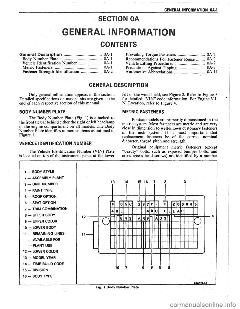
The Body Number Plate (Fig. 1) is attached to
Pontiac models are primarily dimensioned in the
the front tie bar behind either the right or left
headlamp metric system, Most fasteners are metric and are very in the engine On The close in dimension to well-known customary fasteners Number Plate identifies numerous items as outlined in in the inch system. It is most important that Figure 1. re~lacement fasteners be of the correct nominal
VEHICLE IDENTIFICATION NUMBER d&meter, thread pitch and strength.
Original equipment metric fasteners (except
The Vehicle Identification Number (VIN) Plate "beauty" bolts, such
as exposed bumper bolts, and
is located on top of the instrument panel at the lower cross
recess head screws) are identified by a number
1 -- BODY STYLE
2 ASSEMBLY PUNT
3 -- UNIT NUMBER
4 -- PAINT TYPE
5 - ROOF OPTION
6 -- SEAT OPTION
7 - TRIM COMBINATION
8 - UPPER BODY
9 - UPPER COLOR
10 -- LOWER BODY
11 - REMAINING LINES
- AVAILABLE FOR
--PLANT
USE
12 - LOWER COLOR
13 - MODEL YEAR
14 -- TIME BUILD CODE
15 - DIVISION
16 - BODY TvPE
6200224A
Fig. 1 Body Number Plate
Page 1610 of 1825
LIGHTING SYSTEMS AND HORNS 8B-11
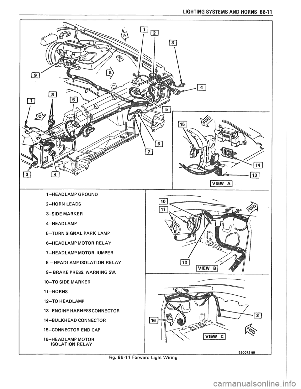
2-HORN LEADS 3-SIDE MARKER
4-HEADLAMP
%-TURN SIGNAL PARK LAMP
6-HEADLAMP MOTOR RELAY
7-HEADLAMP MOTOR JUMPER
8 -HEADLAMP ISOLATION RELAY
9- BRAKE PRESS. WARNING SW.
10-TO
SIDE MARKER
11-HORNS
12-TO
HEADLAMP
13-ENGINE HARNESSCONNECTOR
14-BULKHEAD CONNECTOR
15-CONNECTOR END CAP
16-HEADLAMP MOTOR ISOLATION RELAY
Fig. 8B-1 1 Forward Light Wiring
Page 1612 of 1825
INSTRUMENT PANEL, GAGES & CONSOLE 8C-'I
SECTION 8C
NSTRUMENT PANEL, GAGES & CONSOLE
CONTENTS
General Description ................................... 8C-1
Instrument Panel and Gages ........................ 8C-1
Printed Circuit .......................................... 8C-1
Instruments ................................................... 8C- 1
Speed Sensors
............................ .. ............. 8C- 1
Pinion Gear
............................................. 8C-2
Photo Speed Sensor ................................ 8C-2
PM Generator ................... .. ...... ............... 8C-2
Speedometer ................................................ 8C-2
Mechanical ....................... .. .................... 8C-2
Quartz ........................ .. .......................... 8C-2
Digital .................... .. ...... ................. 8C-2
Fuel Gage .................................................... 8C-2
Temperature Warning Light ...................... 8C-3
Generator Warning Light ............................ 8C-3
Engine Oil Pressure Light ............................ 8C-3
"Service Engine Soon" Light ....................... 8C-3
Upshift Indicator Light .............................. 8C-3
Diagnosis .................... .. ........................... 8C-3
General Information .................................. 8C-3
Instrument Panel & Gages ...................... ..... 8C-3
On-Car Service ......................... .. ........... 8C-4
Instrument Panel Pad ................................... 8C-4
Instrument Panel Cluster ........................... 8C-4
Instrument Panel Carrier ............................. 8C-4
Headlight Switch .......................................... 8C-4
Console Mounted Switches and
Accessories
............................................... 8C-4
Console ......................................................... 8C-4
Speedometer .................................................. 8C-5
Illustra3ions ................................................. 8C-5
IP Pad ........................................................... 8C-5
IP Carrier ................................................... 8C-6
Instrument Cluster ....................................... 8C-6
Lower IP Covers ......................................... 8C-7
IP Trimplates ............................................... 8C-7
IP Hush Panels; with A/C .......................... 8C-8
..................... IP Lower Trim Pad (Console) 8C-8
Map Holder or Map Pocket ........................ 8C-8
IP Hush Panels; without A/C ..................... 8C-9
Radio Mounting ........................................... 8C-9
Subwoofer & Hatch Release
Switches/Covers ........................................ 8C- 10
Foglamp Switch/Cover ................................ 8C- 10
Oil Pressure and Temperature
Switches
..................................................... 8C-11
Heater/Ventilation/Defroster
Ductwork .................................................. 8C- 12
A/C and Defroster Ductwork ..................... 8C-13
Ram Vent System Ductwork ....................... 8C-14
Console Mounted Switches
&
Accessories ................................................. 8C- 14
Dash Insulators
............................................ 8C- 15
Heater Floor Outlet
..................................... 8C-15
................ Headlamp/Parking Lamp Switch 8C- 15
............. Dash Mounted Accessory Switches 8C- 15
GENERAL DESCRIPTION
INSTRUMENT PANEL AND GAGES
INSTRUMENTS
Instruments consist of fuel gage, temperature
The instrument panel on most cars is a sing,e unit indicator light, generator light, oil pressure indicator
design and all parts attach to the main instrument light, and speedometer. See Section 9F for optional
panel with clips and screws. To service the instrument Gages and tachometer. Service on instruments
panel and components see on-car service information, can be obtained through authorized repair stations.
However, knowledge of instrument circuit checks will
PRINTED CIRCUIT
All models are equipped with printed circuits
which supply current to most instrument panel lights
and instruments. These circuits are made of copper foil
which is die cut and bonded to a polyester base film
(usually mylar). The printed circuit electrical power is
supplied by a connector containing several wires, as
shown in the instrument panel wiring harness
installation instructions. The connector also helps
retain the printed circuit to the speedo cluster. The rest
of the circuit is retained by additional connectors (if
used) and snap-in
bulbs/sockets. For individual
printed circuit diagrams, see Section
8A-80/8 1/82/83,
'Instrument Panel'. help
in determining if operating difficulties lie in the
instrument itself or its related circuit.
Instruments have been designed for easy removal
by elimination of separate wiring. With the wiring
provisions integrated with the instrument panel wiring,
the instruments can be removed after removing the
trim and lens.
SPEED SENSORS
There are three speed sensors currently in use:
1. PINION GEAR; used in mechanical systems
2. PHOTO SPEED SENSORS; used in mechanical
systems
3. PM GENERATOR; used in electronic systems
Page 1626 of 1825
INSTRUMENT PANEL, GAGES & CONSOLE 8C-15
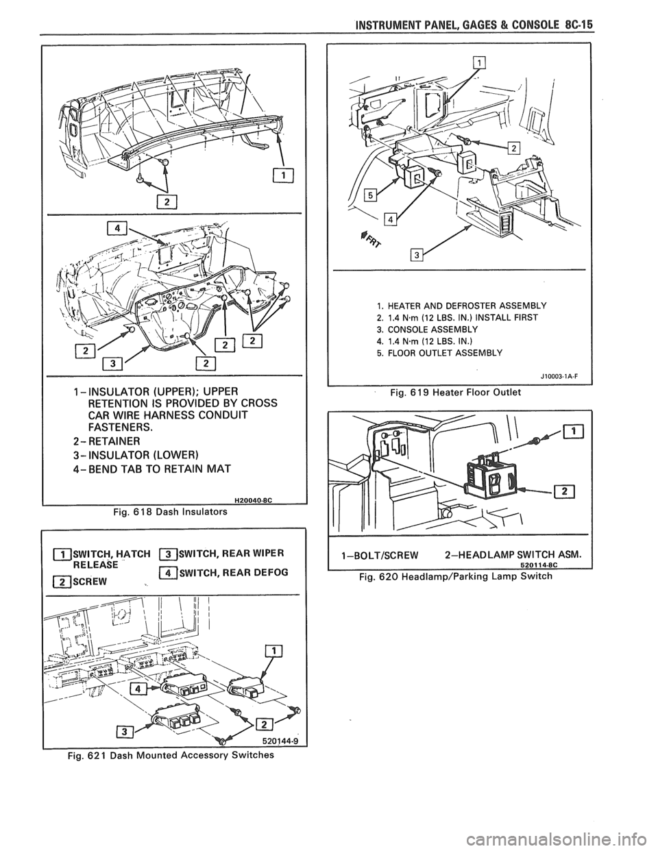
1 -INSULATOR (UPPER); UPPER
RETENTION IS PROVIDED BY CROSS
CAR
WIRE HARNESS CONDUIT
FASTENERS.
2- RETAINER
3- INSULATOR (LOWER)
4- BEND TAB TO RETAIN MAT
1. HEATER AND DEFROSTER ASSEMBLY
2. 1.4
N-rn (12 LBS. IN.) INSTALL FIRST
3. CONSOLE ASSEMBLY
4. 1.4
Narn (12 LBS. IN.)
5. FLOOR OUTLET ASSEMBLY
Fig. 6 19 Heater Floor Outlet
Fig. 6
18 Dash Insulators
SWITCH, HATCH SWITCH, REAR WIPER RELEASE
SCREW SWITCH, REAR DEFOG
1-BOLT/SCREW 2-HEADLAMP
Fig. 620 Headlamp/Parking Lamp Switch
- Fig. 62 1 Dash Mounted Accessory Switches
Page 1677 of 1825
96.4 MISCELLANEOUS ACCESSORIES
DASH AND CONSOLE MOUNTED ACCESSORY
SWITCHES
Installation for various dash and console
mounted accessory switches is shown in Section
8C.
GENERAL DESCRIPIIOM
ELECTRONIC GLARE CONTROL MIRROR
Service procedures regarding this mirror are
found in the Body Section of this manual.
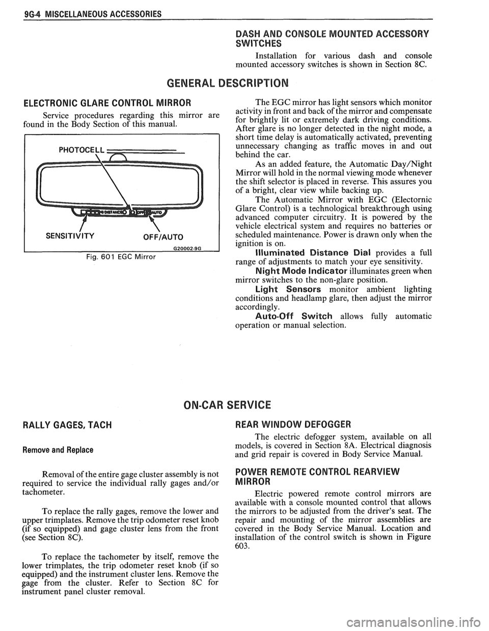
Fig. 601 EGC Mirror
The EGC mirror has light sensors which monitor
activity in front and back of the mirror and compensate
for brightly lit or extremely dark driving conditions.
After glare is no longer detected in the night mode, a
short time delay is automatically activated, preventing
unnecessary changing as traffic moves in and out
behind the car.
As an added feature, the Automatic
Day/Night
Mirror will hold in the normal viewing mode whenever
the shift selector is placed in reverse. This assures you
of a bright, clear view while backing up.
The Automatic Mirror with EGC (Electornic
Glare Control) is a technological breakthrough using
advanced computer circuitry. It is powered by the
vehicle electrical system and requires no batteries or
scheduled maintenance. Power is drawn only when the
ignition is on.
Illuminated Distance Dial provides a full
range of adjustments to match your eye sensitivity.
Night Mode Indicator illuminates green when
mirror switches to the non-glare position.
Light Sensors monitor ambient lighting
conditions and
headlamp glare, then adjust the mirror
accordingly.
Auto-Off Switch allows fully automatic
operation or manual selection.
ON-CAR SERVICE
RALLY GAGES, TACH REAR WINDOW DEFOGGER
Remove
and Replace
The electric defogger system, available on all
models, is covered in Section
8A. Electrical diagnosis
and grid repair is covered in Body Service Manual.
Removal of the entire gage cluster assembly is not
POWER RmOTE CONTROL REARVIEW
required to service the individual rally gages and/or MIRROR
tachometer.
Electric powered remote control mirrors are
available with a console mounted control that allows
To replace the rally gages, remove the lower and the
mirrors to be adjusted from the driver's seat. The
upper trimplates. Remove the trip odometer reset knob repair
and mounting of the mirror assemblies are
(if so equipped) and gage cluster lens from the front covered in
the Body Service Manual. Location and
(see Section
8C). installation of the control switch is shown in Figure
603.
To replace the tachometer by itself, remove the
lower trimplates, the trip odometer reset knob (if so
equipped) and the instrument cluster lens. Remove the
gage from the cluster. Refer to Section
8C for
hstrument panel cluster removal.
Page 1760 of 1825
ROOF - F STYLE 8H-1
SECTION 8H
ROOF
CONTENTS
Formed Headlining .......................................... 8H- 1
Interior Roof Attachments
.............................. 8H- 1
Interior Garnish Moldings .............................. 8H-2
Exterior Roof Moldings and
Attachments
.................................... .... ... 8H-3
Twin Lift-off Panel
......................................... 8H-3
Convertible Top
Top Operation
............................................ 8H-7
Header Inner Garnish
................................. 8H-8
"A" Pillar Inner Garnish
........... .;. .............. 8H-9
Header
"A" Pillar Seal ................................ 8H-9
Side Rail Seal and Retainer
......................... 8H-9
Main Pillar Seal and Retainer
..................... 8H-9
No.
5 Bow Seal .......................................... 8H-9
No. 1 Bow Garnish Molding
....................... 8H-9
Top Cover Assembly
.................................... 8H- 1 1
Side Stay Pads ............................................. 8H-13
Rear Stay Pads ............................................ 8H- 13
No.
1 and No. 2 Bows ................................. 8H- 13 NO. 3
BOW
.................................................... 8H-15
NO. 4 BOW ................................................ 8H-15
NO. 5 BOW ................................................. 8H-15
Top Stack Assembly Complete .................... 8H- 16
Quarter Inner Upper Trim Cap
.................. 8H- 17
Quarter Trim Panel
.................................... 8H- 17
Quarter Cap Belt Molding
........................... 8H- 17
Tonneau Panel Latch
................................. 8H- 17
Tonneau Release Solenoid
........................... 8H- 17
No. 5 Bow Release Handle
.......................... 8H- 19
No.
5 Bow Latch ....................................... 8H-19
Tonneau Panel
.......................................... 8H- 19
Tonneau Panel Seal
............................. ......... 8H-20
Deck Lid Spoiler ........................................ 8H-2 1
Center High Mount Stop Lamp .................. 8H-21
Deck Lid .................................................... 8H-21
Deck Lid Panel Seal
................................. 8H-22
Door Cap Belt Molding ............................... 8H-22
Front Belt Retractor Assembly ................... 8H-22
FORMED HEADLINING 1. Load the headlining through the rear
The one-piece formed headlining (Fig. 1) consists
of a molded fiberglass substrate covered with a foam
and cloth facing. The one-piece construction requires
the headlining be serviced as a complete assembly.
The headlining is held partially in place by
retaining fasteners located in the headlining which fit
into slots in the roof panel. Final attachment is
accomplished when the interior moldings and
attaching screws that retain the sunshade brackets,
dome lamp base and coat hooks are installed.
Removal
1. Remove the following items:
e Back body opening upper garnish molding
r Windshield side upper garnish molding (1,
Fig. 3 or
6)
e Rear vertical garnish molding
a Windshield header courtesy reading and
console lamp
e Sunshades
e Partially remove shoulder belt bezel and
belt
a Coat hooks and rail panel inserts
2. Grasp headlining assembly with both hands at
outer edges and move to the right of centerline to
disengage fastener assemblies from front
attaching slots.
3. Remove headlining assembly through right front
door.
lnstallation
Care must be exercised when loading assembly.
Excessive flexing may result in damage. compartment
opening.
2. Align headlining with cutouts for sunshades and
dome lamp and install sunshade brackets and
dome lamp base. Do not tighten sunshade bracket
and dome lamp attaching retainers completely
until headlining is aligned properly at all
hardware attaching locations.
3. Align headlining to roof inner panel with
fasteners positioned over holes in roof panel and
using palm of hand, push up on headlining at
fastener locations.
4. Install all previously removed hardware and
interior moldings.
INTERIOR ROOF ATTACHMENTS
DOME LAMPS
The dome lamp operates in conjunction with the
door jamb switch and/or the
headlamp switch. The
dome lamp harness extends up the right windshield
pillar, outboard of the sunshade support and across the
roof inner panel to the dome lamp.
Removal and Installation (Typical)
1. Grasp lens portion of dome lamp assembly,
squeeze and pull down to remove.
2. Remove bulb from terminal clips.
3. Remove retainers from studs.
4. Disengage wire harness from lamp housing and
remove dome lamp housing.
5. To install dome lamp assembly, reverse removal
procedure.