1988 PONTIAC FIERO coolant temperature
[x] Cancel search: coolant temperaturePage 22 of 1825
MAINTENANCE AND LUBRICATION OB-5
Throttle linkage inspection -- Inspect for inter-
ference, binding, damaged or missing parts.
Engine drive belts inspection - Inspect all
belts for cracks, fraying and wear. Adjust or replace as
needed.
Rear axle service (if equipped) - Check gear
lubricant level and add if needed. For cars equipped with a
limited slip rear axle, fluid does not require changing
(except Caprice and Corvette
- change fluid and required
additive at first
7,500 miles (12 500 km). See your
Owner's Manual or "Recommended Fluids
& Lubricants
Chart" in this section.
IF YOU USE YOUR GAR TO PULL A TRAILER,
CHANGE GEAR LUBRICANT EVERY 7,500 MILES
(12 500 KM).
NOTICE: A large loss in this system may indicate a
problem. Have it inspected and repaired at once.
Power antenna - Clean and then lubricate power
antenna mast. The proper lubricant as shown in Figure
OB-2 should be used.
AT LEAST ONCE A YEAR
Lap and shoulder belts condition and opera-
tion
- Inspect belt system, including webbing, buckles,
latch plates, retractors, guide loops and anchors.
Moveable head restraint operation - On cars
with moveable restraints, make sure restraints stay in the
desired position. (See adjustment instructions in your
Owner's Manual.)
Seatback latch and recliner operation on
cars equipped
with recliner seat --- Be sure seat-
backs latch on those cars with folding seats using mechan-
ical latches. Make sure the recliner is holding by pushing
and pulling on the top of the
seatback while it is reclined.
See your Owner's Manual for seat operating information.
Spare tire and jack storage- Be alert to rattles
in rear of car. Make sure the space tire, all jacking equip-
ment, any tire inflator and any covers or doors are securely
stowed at all times. Oil jack ratchet or screw mechanism
after each use.
Key lock service - Lubricate key lock cylinder at
least annually.
Body lubrication service - Lubricate all body
door hinges including the tailgate or hatchback lid (if
equipped). Also lubricate the body hood, fuel door and
rear compartment hinges and latches including interior
glove box and counsel doors, and any folding seat
hardware.
"Fansmissionltransaxle neutral or clutch
starl switch operation
CAUnON: Before pedorming the follow-
ing safety switch check, be sure to have
enough room around the car. Then, firmly
apply both the parking brake (see your
Owner's Manual for procedure) and the
regular brakes. Do not use the accelerator pedal.
If the engine
starls, be ready to turn
off the ignition promptly. Take these pre-
cautions because the car could move
without warning and possibly cause per-
sonal injury or properly damage. On auto-
matic transmissionltransaxle cars, try to
starl the engine in each gear. The starler
should crank only in "Park" or "Neutral."
On manual transmissionltransaxle cars,
place the
shiR lever in "Neutral," push the
clutch halfway and try to starl. The starler
should crank only when the clutch is fully
depressed.
Steering column lock operation
- While
parked, try to turn key to "Lock" in each gear range. The
key should turn to "Lock" only when gear is in "Park" on
automatic or "Reverse" on manual
transmissionltransax-
le. On cars with key release lever, try to turn key toULock"
without depressing the lever. The key should turn to
"Lock" only with the key lever depressed. On all vehicles,
the key should come out only in "Lock."
Parking brake and transmissionltransaxle
"Park" mechanism operation
CAUT1ON:Before checking the holding
ability of the parking brake and automatic
transmissionltransaxle "Park" mecha-
nism, park on a fairly steep hill with
enough room for movement in the down-
hill direction. To reduce the risk of person-
al injury or property damage, be prepared
to apply the regular brakes promptly if the
car begins to move.
To check the parking brake, with the engine running and
transmission/transaxle in "Neutral." slowly remove foot
pressure from the regular brake pedal (until the car is held
by only the parking brake).
To check the automatic transmissionltransaxle "Park"
mechanism holding ability, release all brakes after shift-
ing the transmissionltransaxle to "Park."
ljnderbody flushing - At least every spring,
tlush from the underbody with plain water any corrosive
materials used for ice and snow removal and dust control.
Take care to thoroughly clean any areas where mud and
other debris can collect.
Sediment packed in closed areas
of the vehicle should be loosened before being flushed.
Engine cooling system service - Inspect
coolant and freeze protection. If dirty or rusty, drain, flush
and refill with new coolant. Keep coolant
at the proper
mixture as specified in your Owner's Manual. This pro-
vides proper freeze protection. corrosion inhibitor level
and engine operating temperature. Inspect hoses and re-
place if cracked. swollen or deteriorated. Tighten hose
clamps. Clean outside of radiator and air conditioning
condensor. Wash radiator filler cap and neck.
To help
ensure proper operation. a pressure test of both the cooling
system and cap is also recommended. (See maintenance
schedule charts in Figure
OB-l for the recommended
coolant change interval.)
Page 24 of 1825
HEATING AND VENTILATION 1A-1
SECTION 1A
NG AND VENT
CONTENTS
General Description ................................. 1A-1
Diagnosis - Heater Trouble ...................... 1A-5
Insufficient Heating or Defrosting .............. 1A-5
Blower Electrical ......................................... 1A-7
....... Improper Air DeliveryINo Mode Shift 1 A-8
Too Much Heat .......................................... 1A-9 ....................................................... Controls 1A-10 ............................................... Blower Noise 1A-11
....................................... On-Vehicle Sewice 1A-13
.......................... Heater Control Assembly 1 A- 13
....................................... Blower Switch 1A- 13
.................................. Temperature Cable
1 A- 13
.......................................... Heater Core 1 A- 13
................................. Vent Control Cable 1 A- 13
Lower Heater Outlet
................................ 1A-14
........................................ Blower Motor 1A-14
GENERAL DESCRIPTION
The base heater system is designed to provide
heating, ventilation, windshield defrosting and on some
cars, side window defogging. Ram air ventilation is
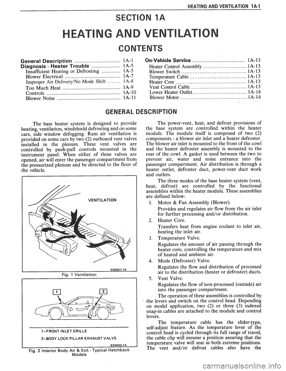
provided on some cars by two (2) outboard vent valves
installed in the plenum. These vent valves are
controlled by push-pull controls mounted in the
instrument panel. When either of these valves are
opened, air will enter the passenger compartment from
the pressurized plenum and be directed to the floor of
the vehicle.
/& VENTILATION
1-FRONT INLET GRILLE
2-BODY LOCK PILLAR EXHAUST VALVE
Fig. 2 Interior Body Air & Exit - Typical Hatchback Models
The power-vent, heat, and defrost provisions of
the base system are controlled within the heater
module. The module itself is composed of two (2)
components
- a blower air inlet and a heater defroster.
The blower air inlet is mounted to the front of the cowl
and the heater defroster assembly is mounted to the
rear of the cowl. A gasket is used between the two to
prevent air, water and noise entrance into the
passenger compartment. Air distribution is through a
heater outlet, defroster duct, power-vent duct work
and outlets.
The three modes of the base heater system (vent,
heat, defrost) are controlled by the functional
assemblies within the heater module. These assemblies
are defined below:
1. Motor & Fan Assembly (Blower).
Provides and regulates air flow from the air inlet
for further processing and/or distribution.
2. Heater Core.
Transfers heat from engine coolant to inlet air,
heating the inlet air.
3. Temperature Valve.
Regulates the amount of air passing through the
heater core, controlling the temperature and mix
of heated and ambient air.
4. Mode (Defroster) Valve.
Regulates the flow and distribution of processed
air to the distribution (heater or defroster) ducts.
5. Vent Valve.
Regulates the flow of non-processed (outside) air
into the passenger compartment.
The operation of these assemblies is controlled by
the levers and switch on the control head. Depending
on model application, two (2) or three
(3) indexed
snap-in cables are attached to the module and control
levers.
The temperature cable has the slider-type,
self-adjust feature. As the temperature lever of the
control head is cycled through its full range of travel,
the cable clip will assume a position assuring that the
temperature valve will seat in both extreme positions.
The vent and/or defrost cables also have the
Page 29 of 1825
1A-6 HEATING AND VENTILATION
CHECK VEHICLE FOR
COLD AIR LEAKS AT DASH,
HEATER CASES AND FROM
VENTS. CHECK
UNDERSEAT FOR
OBSTRUCTIONS.
w
TEN FOR DOOR SLAM PRIOR TO THE END
CHECK THE TEMPERA-
TURE DOOR ADJUSTMENT,
CABLES, LINKAGE AND AD-
JUST TO FULL HOT. CHECK
I
WITH THE TEMPERATURE
DOOR FULL HOT, START THE
VEHICLE. CHECK THE TEMPER- ATURE OF THE HEATER INLET
AND OUTLET HOSES BY FEEL.
THE AIR TEMPERATURE
AROUND THE HOSES MUST BE AT LEAST
85OF.
I
WITH THE BLOWER ON
HIGH, MOVE THE TEMP-
ERATURE LEVER FROM
FULL HOT TO FULL
COLD AND LISTEN FOR
AIRFLOW CHANGE.
CHECK THE TEMPER-
ATURE DOOR AD-
JUSTMENT, CABLES,
CONTROL, LINKAGE
&
BETWEEN THE
COOLANT REPLACE.
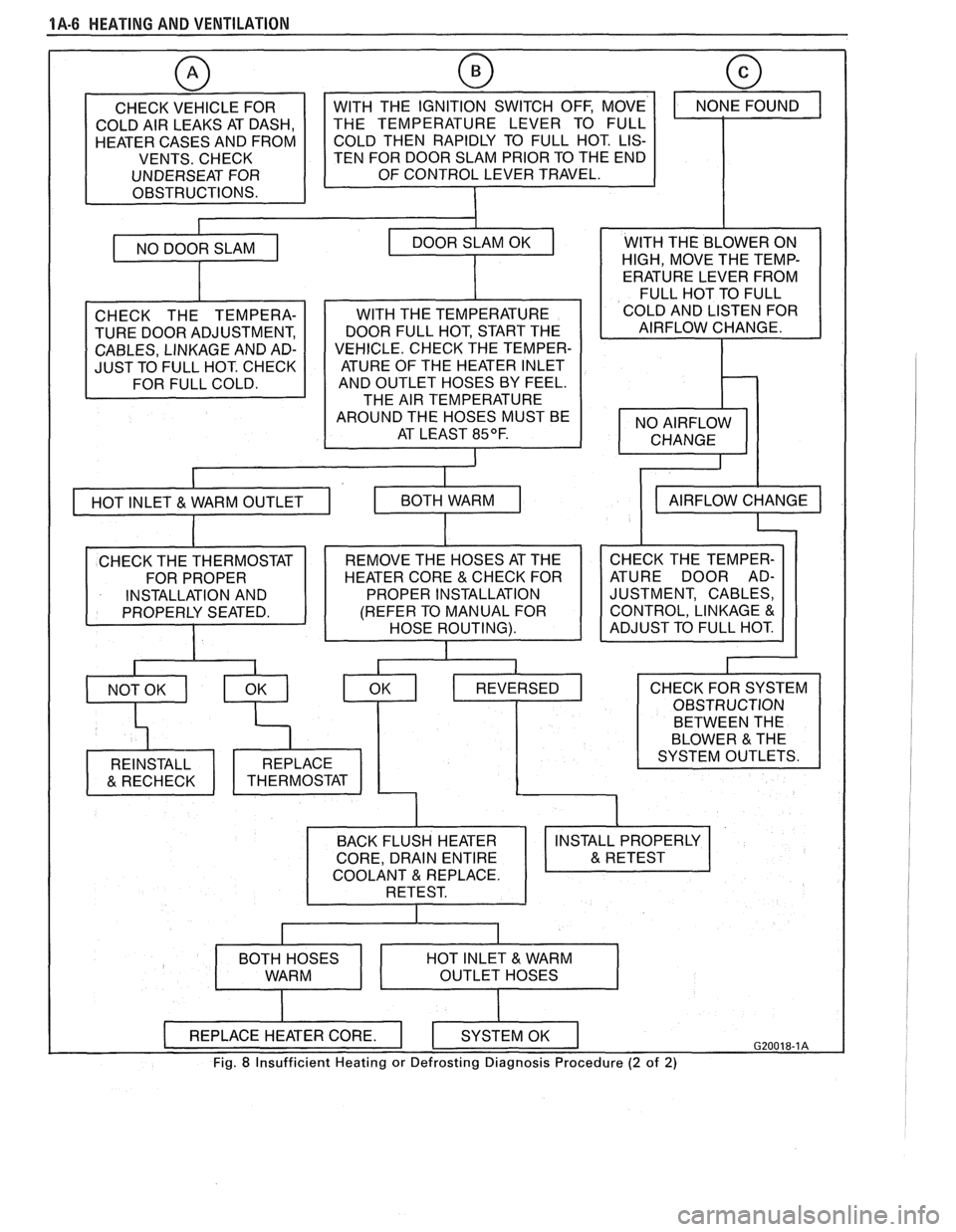
Fig. 8 Insufficient Heating or Defrosting Diagnosis Procedure (2 of 2)
Page 46 of 1825
AIR CONDITIONING 1 B-3
A low-side pressure Schrader valve service fit-
ting is located near the top of the accumulator. A
similar Schrader fitting may be provided for mounting
the pressure cycling switch. It is not necessary to dis-
charge the system to replace the switch. The accumu-
lator is serviced only as a replacement assembly.
Heater Core
The heater core heats the air before it enters the
car. Engine coolant is circulated through the core to
heat the outside air passing over the fins of the core.
The core is functional at all times (no water valve) and
may be used to temper conditioned air in
A/C mode,
as well as heat or vent mode.
SYSTEM COMPONENTS --- CON"FOL
Controller
The operation of the A/C system is controlled by
the switches and the lever on the control head. The
compressor clutch and blower are connected electri-
cally to the control head by a wiring harness. The
blower circuit is open in the off mode and air flow is
provided by the four blower speeds available in the
remaining modes. Cooled and dehumidified air is
available in the max, normal, bi-level and defrost
modes.
Temperature is controlled by the position of the
temperature lever on the control head. A cable con-
nects this lever to the temperature door which controls
air flow through the heater core. As the temperature
lever is moved through its range of travel, a sliding
clip on the cable at the temperature valve connection
should assume a position assuring that the temperature
door will seat in both extreme positions. Temperature
door position is independent of mode selection. The
temperature cable attaches to the right side of the air
conditioning module. The temperature door on some
models is controlled electrically, thereby eliminating
the need for the temperature cable.
The electric engine cooling fan on some cars is
not part of the
A/C system; however, the fan is
operational any time the
A/C control is in Max.,
Norm, or Bi-Level modes. Some models provide for
engine cooling fan operation when the controller is in
the defrost mode. This added feature is part of the
A/C
controller function and is aimed at preventing exces-
sive compressor head temperatures. It also allows the
A/C system to function more efficiently. On some
models during road speed (above
35 mph) conditions
when air flow through the condenser coil is adequate
for efficient cooling, the engine cooling fan will be
turned off. The operation of the cooling fan is con-
trolled by the ECM through the cooling fan relay.
Complete wiring diagrams and diagnosis for the
AIC Electrical System are in Section 8A. Section 8A
also contains additional diagnostic information
regarding air flows and vacuum logic.
Vacuum Lines
Vacuum lines are molded to a connector which
is attached to a vacuum control switch on the control
head assembly.
In case of leakage or hose collapse, it will not be
necessary to replace the entire harness assembly.
Replacement can be made by cutting the hose and
inserting a plastic connector. If an entire hose must be
replaced, cut all hoses off at the connector and then
attach hoses directly to the control head vacuum
switch. (NOTE: The Fiero uses an electric motor to
control mode selection. Therefore, it will not have a
vacuum harness.
)
Vacuum Tank
During heavy acceleration, the vacuum supply
from the carburetor drops. A check valve in the vac-
uum tank maintains vacuum so that, under load condi-
tions, vacuum will be available for continuous use.
REWVS AND SWITCHES
High-Pressure Compresssr Gut-OFF Switch
The high-side, high-pressure cut-off switch in
the rear head of the compressor is a protective device
intended to prevent excessive compressor head pres-
sures and reduce the chance of refrigerant escape
through a safety relief valve. Normally closed, this
switch will open the circuit at a high-side pressure of
approximately 2700
kPa (430 psi 9 20 psi) and
reclose the circuit at approximately 1379 kPa (200 psi
9 50 psi).
Lsw-Pressure Cut-On Switch
Compressor protection is provided on some cars
by a low-pressure cut-off switch which will open in
the event of a low-charge condition. This switch can
be located in the liquid line or in the rear head of the
compressor. This switch will also keep the compres-
sor from running during cold weather.
Pressure eyesing Switch
The refrigeration cycle (on and off operation of
the compressor) is controlled by a switch which
senses the low-side pressure as an indicator of evapo-
rator temperature. The pressure cycling switch is the
freeze protection device in the system and senses
refrigerant pressure on the suction side of the system.
This switch is located on a standard Schrader-type
valve low-side fitting. This switch also provides com-
pressor cut-off during cold weather.
Additional compressor protection results from
the operating characteristics of the low-side pressure
cycling system. If a massive discharge occurs or the
orifice tube becomes plugged, low-side pressures
could be insufficient to close the contacts of the pres-
sure switch. In the event of a low charge, insufficient
cooling accompanied by rapid compressor clutch
cycling will be noticed at high air temperatures.
Page 51 of 1825

1B-8 AIR CONDITIONING
INSUFFICIENT COQblNG "CHART A
A/C FUSE AND/OR GAGE FUSE.
OR DISCONNECTED
AlC WIRE CONNECTOR.
. CHECK BLOWER FOR FAN OPERATION.
. ENGINE COOLING FAN OPERATION (FAN OPERATES IN ALL A/C MODES AS FOLLOWS:
A. DISCONNECT ENGINE COOLANT TEMPERATURE FAN SWITCH.
8. WITH IGNITION ON AND ENGINE NOT RUNNING, SET A/C CONTROL TO A/C MODE.
C. ENGINE COOLING FAN SHOULD RUN.
D. RECONNECT ENGINE COOLANT TEMPERATURE FAN SWITCH.
REPLACE COMPRES-
SOR ASSEMBLY. RE-
PLACE ORIFICE. EVA-
CUATE AND CHARGE. AS
REQUIRED
AND 'HIGH' BLOWER.
T
AUXIL I ARY FAN IN T OF VEHICLE.
I OFF ALL THE TIME I
RESTRICTION IN HIGH
SIDE OF SYSTEM.
VISUALLY CHECK FOR
FROST SPOT TO LOCATE
RESTRICTION. REPAIR.
Figure
8 C.C.O.T. NC System Insufficient Cooling Diagnostic Procedure (1 of 4)
Page 349 of 1825
6-4 ENGINE GENERAL INFORMATION
Bent connecting rod.
HEAVY KNOCK H0"FVVI"F TORQUE APPLIED
Broken balancer, or pulley hub. Replace parts as e Exhaust system grounded. Reposition as
necessary. necessary.
Loose torque converter bolts. Flywheel
cracked.
e Excessive main bearing clearance. Replace as
Accessory belts too tight or nicked. Replace
necessary.
and/or tension to specs as necessary.
e Excessive rod bearing clearance. Replace as
necessary.
LIGHT KNOCK HOT
Detonation or spark knock. Check operation of e Loose torque converter bolts.
EST or ESC (See Section
6D or 6E). Check e Exhaust leak at manifold. Tighten bolts and/or
engine timing and fuel quality.
replace gasket.
8 Excessive rod bearing clearance. Replace
bearings as necessary.
KNOCKS ON INITIAL START-UP BUT ONLY LASTS A FEW SECONDS
Noisy mechanical fuel pump. Replace pump.
When the engine is stopped, some valves
will be open. Spring pressure against lifters
Improper oil viscosity. Install proper oil viscosity will
tend to bleed lifter down. Attempts to
for expected temperatures. See Owner's Manual. repair
should be made only if the problem
is consistent.
Hydraulic lifter bleed down. Clean, test and @ Excessive crankshaft end clearance. Replace
replace as necessary. crankshaft
thrust bearing.
@ Excessive front main bearing clearance. Replace
worn parts.
KNOCKS AT IDLE HOT
Loose or worn drive belts. Tension and/or @ Excessive piston pin clearance. Ream and install
replace as necessary. oversize pins. (VIN R and 2) or replace piston
A/C Compressor or generator bearing. Replace and
pin.
as necessary.
e Connecting rod alignment. Check and replace
rods as necessary.
Noisy mechanical fuel pump. Replace pump.
8 Insufficient piston to bore clearance. Hone bore
Valve train. Replace parts as necessary. and
fit new piston.
@ Loose crankshaft balancer. Torque and/or
Improper oil viscosity. Install proper viscosity oil
replace worn parts.
for expected temperature4 See Owner" e Piston pin offset to wrong side. Install correct
ENGINE OVERHEATS
Coolant system leak, oil cooler system leak, or
2. Belt slipping or damaged. Replace tensioner, or
coolant recovery system not operating. Check for belt, as required.
leaks and correct as required. Check coolant
3. Thermostat stuck closed. Check and replace if
recovery tank, hose and radiator cap.
required.
4. Electrical cooling fan operation. See the
ELECTRICAL TROUBLESHOOTING
MANUAL.
5. Head gasket leaking. Check and repair as
required.
Page 412 of 1825
ENGINE COOLING 6B-1
SECTION 6B
NE COOL
General Description ................................ 6B- 1 Off-Vehicle Leak Testing ............................... 6B-9
Radiator
...................................................... 6B- 1 Repairable Leaks ........................ ... .......... 6B- 10
Radiator Cap
......................... .. ............... 6B- 1 Repair Methods ................................................ 6B- 10
Recovery Bottle ......................................... 6B-2 Cooling Fin Removal ................................ 6B- 10 - ............................................. Fans ............................................................... 6B-2 Tube Blocking 6B- 1 1 ............ Header Repair ....................... .... 6B- 1 1 Temperature Switch ..................................... 6B-2 General Core Repair 6B- 1 1 ....................................
........................... Coolant Temperature Fan Switch ................ 6B-2 Tank
Gasket ~eik Repair 6B- 12
................... Thermostat .. 6B-3 Oil
Cooler Gasket Replacement
6B- 13 ............... ................................
...........................................................
Coolant Recovery System 6B-3 Recore 6B- 14 ............................. Special Tools ..................................................... 6B- 14 Diagnosis ..................................................... 6B-3
.............................. ..................................... Service Procedures 6B-3 On-Vehicle Service 6B-14
Cooling System Care
............................... 6B-3 Thermostat ....................................... 6B-14
Draining and Refilling the Cooling Electric Cooling Fan ............................. 6B-15
System
................................................... 6B-7 Water Pump .................... .... ......... 6B-15
Drive Belt
...................... .. .......................... 6B-7 Coolant Recovery Bottle ........................ 6B-16
.......................................... Aluminum Radiator Service .................... 6B-8 Radiator 6B-17
Diagnosis .................................................... 6B-8
Leak Testing
.............................................. 6B-8
On-Vehicle Pressure Testing
...................... .... 6B-9
GENERAL DESCRIPnIBN
The cooling system maintains engine temperature
5" below the filler neck which reads, "Important - for
at an efficient level during all engine operating repair see Harrison Service Manual". Service
conditions. When the engine is cold the system cools procedures for the aluminum plastic radiator are
slowly, or not at all, to allow the engine to warm up described in that manual and in this section.
quickly.
The cooling system includes a radiator and
Radiator Cap
recovery sub-system, cooling fan, thermostat and
housing, water pump, and drive belts.
Operation of the cooling system requires proper
functioning of all components. Coolant is drawn from
the radiator by the water pump and circulated through
water jackets in the engine block, intake manifold, and
cylinder
head(s), and then directed back to the radiator
where it's cooled.
This system directs some coolant through hoses
to the heater core, to provide for heating and
defrosting. A recovery bottle is connected to the
radiator to recover coolant displaced by expansion
from high temperatures and maintain correct coolant
level. As the coolant cools and contracts it is drawn
back into the radiator by vacuum.
RADIATOR
A cross-flow radiator is used on all models. Tanks
in this type radiator are located to the right and left of
the core, instead of above and below.
Radiators used with automatic transmissions
have oil coolers with inlet and outlet fittings for
transmission fluid circulation. Cars with manual
transmissions use radiators without oil coolers.
Vehicles equipped with air conditioning use a radiator
with extra cooling capability.
An aluminum-plastic radiator, used on some
models, can be identified by a note on the outlet tank A pressure-vent
cap is used on the cross-flow
radiator to allow a buildup of
103 kPa (15 psi) in the
cooling system. This pressure raises the boiling point
of coolant to approximately 125°C (262°F) at sea level.
Do not remove radiator cap to check engine
coolant level; check coolant visually at the
see-through coolant reservoir. Coolant should
be added only
to the reservoir.
CAUTION: As long as there
is
pressure in the cooling system, the
temperature can be considerably
higher than the boiling temperature
of
the solution in the radiator without
causing the solution to boil. Removal
of the radiator cap while engine is hot
and pressure is high will cause
the
solution to boil instantaneously and
possibly with explosive
force, spewing
the solution over engine, fenders and
person removing cap. If the solution
contains flammable antifreeze, such
as alcohol (not recommended for use
at any time), there is also the
possibility
of causing a serious fire.
The pressure-type radiator filler cap contains a
blow off or pressure valve and a vacuum or
atmospheric valve (Figure
1). The pressure valve is
held against its seat by a spring of pre-determined
Page 413 of 1825
BB-2 ENGINE COOLING
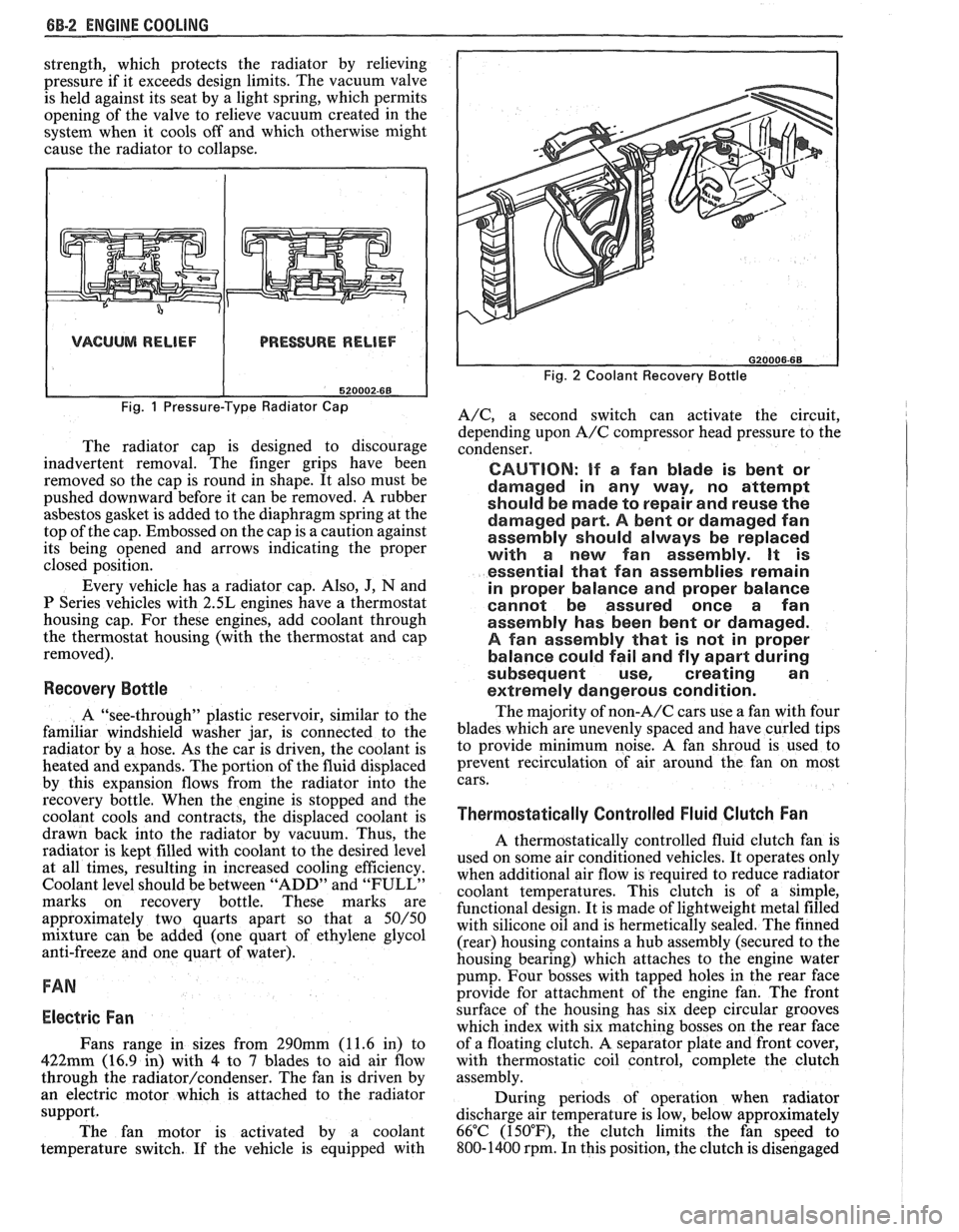
strength, which protects the radiator by relieving
pressure if it exceeds design limits. The vacuum valve
is held against its seat by a light spring, which permits
opening of the valve to relieve vacuum created in the
system when it cools off and which otherwise might
cause the radiator to collapse.
VACUUM RELIEF PRESSURE RELIEF
Fig. 1 Pressure-Type Radiator Cap
The radiator cap is designed to discourage
inadvertent removal. The finger grips have been
removed so the cap is round in shape. It also must be
pushed downward before it can be removed. A rubber
asbestos gasket is added to the diaphragm spring at the
top of the cap. Embossed on the cap is a caution against
its being opened and arrows indicating the proper
closed position.
Every vehicle has a radiator cap. Also,
J, N and
P Series vehicles with 2.5L engines have a thermostat
housing cap. For these engines, add coolant through
the thermostat housing (with the thermostat and cap
removed).
Recovery Bottle
A "see-through" plastic reservoir, similar to the
familiar windshield washer jar, is connected to the
radiator by a hose. As the car is driven, the coolant is
heated and expands. The portion of the fluid displaced
by this expansion flows from the radiator into the
recovery bottle. When the engine is stopped and the
coolant cools and contracts, the displaced coolant is
drawn back into the radiator by vacuum. Thus, the
radiator is kept filled with coolant to the desired level
at all times, resulting in increased cooling efficiency.
Coolant level should be between "ADD" and
"FULL"
marks on recovery bottle. These marks are
approximately two quarts apart so that a
50/50
mixture can be added (one quart of ethylene glycol
anti-freeze and one quart of water).
FAN
Electric Fan
Fans range in sizes from 290mm (11.6 in) to
422mm (16.9 in) with 4 to 7 blades to aid air flow
through the
radiator/condenser. The fan is driven by
an electric motor which is attached to the radiator
support.
The fan motor is activated by a coolant
temperature switch. If the vehicle is equipped with
Fig. 2 Coolant Recovery Bottle
A/C, a second switch can activate the circuit,
depending upon
A/C compressor head pressure to the
condenser.
CAUTION: If a fan blade is bent or
damaged in any way, no attempt
should be made to repair and reuse the
damaged part.
A bent or damaged fan
assembly should always be replaced
with a new fan assembly. It is
essential that fan assemblies remain
in proper balance and proper balance
cannot be assured once a fan
assembly has been bent or damaged.
A fan assembly that is not in proper
balance could fail and fly apart during
subsequent use, creating an
extremely dangerous condition.
The majority of non-A/C cars use a fan with four
blades which are unevenly spaced and have curled tips
to provide minimum noise.
A fan shroud is used to
prevent recirculation of air around the fan on most
cars.
Thermostatically Controlled Fluid Clutch Fan
A thermostatically controlled fluid clutch fan is
used on some air conditioned vehicles. It operates only
when additional air flow is required to reduce radiator
coolant temperatures. This clutch is of a simple,
functional design. It is made of lightweight metal filled
with silicone oil and is hermetically sealed. The finned
(rear) housing contains a hub assembly (secured to the
housing bearing) which attaches to the engine water
pump. Four bosses with tapped holes in the rear face
provide for attachment of the engine fan. The front
surface of the housing has six deep circular grooves
which index with six matching bosses on the rear face
of a floating clutch. A separator plate and front cover,
with thermostatic coil control, complete the clutch
assembly.
During periods of operation when radiator
discharge air temperature is low, below approximately
66°C (150°F), the clutch limits the fan speed to
800- 1400 rpm. In this position, the clutch is disengaged