1988 PONTIAC FIERO heating
[x] Cancel search: heatingPage 2 of 1825
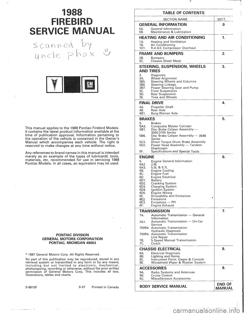
1988
SER
This manual applies to the 1988 Pontiac Firebird Models.
It contains the latest product information available at the
time of publication approval. lnformation pertaining to
the operation of the vehicle is contained in the Owner's
Manual which accompanies each vehicle. The right is
reserved to make changes at any time without notice.
Any references to brand names in this manual is intended
merely as an example of the types of
lubricant% tools,
materials, etc, recommended for use in servicing 1988
Pontiac Models. In all cases, an equivalent may be used.
PONTIAC DIVISION
GENERAL
MOTORS CORPORATION
PONTIAC, MICHIGAN 48053
1987 General Motors Corp. All Rights Reserved.
No part of this publication may be reproduced, stored in any
retrieval system or transmitted in any form or by any means,
including but not limited to electronic, mechanical,
photocopying, recording or otherwise, without the prior written
permission of General Motors Corp. This includes all text,
illustrations, tables and charts.
S-881 OF 9-87 Printed in Canada
TABLE OF CONTENTS
SECTION NAME
GENERAL INFORMATION
OA. General lnformation
OB. Maintenance & Lubrication
1 SECT.
HEATING AND AIR CONDITIONING
1A. Heating and Ventilation
1 B. Air Conditioning
1D1. R-4 AIC Com~ressor Overhaul
FRAME AND BUMPERS
2B. Bumpers 2C. Chassis Sheet Metal
STEERING, SUSPENSION, WHEELS
AND TIRES
3. Diagnosis
3A. Wheel Alignment
3B5. Steering Wheels and Columns 3B6. Steering Linkage 3B7. Power Steering Gear and Pump
3C. Front Suspension
3D. Rear Suspension
3E. Tires and Wheels
FINAL DRIVE
4A. Propeller Shaft
4B. Rear Axle
4B1. Bora-Warner Axle
BRAKES 5. Brakes 5A3. Comoosite Master Cvlinder 5B1. Disc r rake Caliper ~ssembly - 300013100 Series 5B6. Disc Brake Caliper Assembly - 3548
Series
5C3. Direct Torque Drum Brake Assembly 5D2. Power Head Assembly - Tandem Diaohraam 5F. ~~ecifications and Special Tools
ENGINE 6. Engine General lnformation 6A2. 2.8L 6A3. 5.OL & 5.7L 6B. Engine Cooling
6C. En~ine Fuel
6D. ~ngine Electrical 6D1. Battery 6D2. Cranking System 6D3. Charging System 6D4. Ignition System 6D5. Engine Wiring
6E. Driveabilitv and Emissions
6E2. ~missions' 6E3. Emissions - PFI
6F. Engine Exhaust
TRANSMISSION 7A. Automatic Transmission - General
lnformation
7A1. Automatic Transmission - On-Car
Service
700R4. Automatic Transmission Hydraulic Diagnosis
700R4. Automatic Transmission Unit Repair
76. 5-Speed Manual Transmission
7C. Clutch
CHASSIS ELECTRICAL 8A. Electrical Diagnosis
8B. Lighting and Horns
8C. Instrument
Panel, Gages
& Console
8E. Windshield Wiper &Washer System
ACCESSORIES 9A. Radio Systems and Antennas 9B. Cruise Control 9G. Miscellaneous Accessories
I BODY SERVICE MANUAL END
OF
MANUAL
Page 20 of 1825
F CARLINE
ITEM 10
TransmissionRransaxle Service
The manual transmission or transaxle fluid does not
require changing. (Corvette only.) Change fluid in over-
drive unit every 30,000 miles (50 000 km).
For automatic transmissions or transaxles, change
both the fluid and filter every 15,000 miles (25 000 km) if
the car is mainly driven under one or more of these
conditions:
@ In heavy city traffic where the outside temperature
regularly reaches 90°F (32°C) or higher.
@ In hilly or mountainous terrain.
@ Frequent trailer pulling.
@ Uses such as found in taxi, police car or delivery
service.
If you do not use your car under any of these condi-
tions, change both the fluid and filter every 100,000 miles
(160 000 km). See you Owner's Manual for further
details.
ITEM 11
Spark Plug Service*
Replace spark plugs with type listed in your Owner's
Manual.
ITEM 12
Spark Plug Wire Inspection*
Clean wires and inspect for burns, cracks or other dam-
age. Check the wire boot fit at distributor and at spark plugs.
Replace wires as needed.
ITEM 13
Positive Crankcase Ventilation (PCV) Valve
Inspection*
Inspect valve for proper function. Replace valve if
necessary as well as any worn, plugged or collapsed
hoses.
ITEM 14
EGR System Service*
Conduct EGR System Service as referenced in the
EGR System Chart shown in the appropriate 6E Section.
Also, refer to your GM maintenance schedule booklet for
specific applications.
ITEM 15
Air Cleaner and PCV Filter Replacement*
On 1.6 and 2.0 liter engines, replace every 50,000
miles (80 000 km). On all other engines, replace every
30,000 miles (50 000 km). Replace more often under
dusty conditions. Ask your dealer for the proper replace-
ment interval for your driving conditions.
MAINTENANCE AND LUBRICATION 08-3
ITEM 16
Engine Timing Check*
Adjust timing to underhood label specifications. If
no specifications are shown, no adjustment is needed.
ITEM 17
Fuel Tank, Cap and Lines Inspection*
Inspect fuel tank, cap and lines (including fuel rails
and injection assembly, if so equipped) for damage or
leaks. Inspect fuel cap gasket for an even filler neck
imprint or any damage. Replace parts as needed.
ITEM 18
Thermostatically Controlled Air Cleaner
Inspection*
If your car is equipped, inspect all hoses and ducts
for proper hookup. Make sure valve works properly.
OWNER INSPECTIONS AND SERVICES
Listed below are inspections and services which
should be made by either you or a qualified technician at
the intervals shown to help ensure proper safety, emission
performance and dependability of your car. Take any
problems promptly to your dealer or another qualified
technician for service advice. Whenever repairs are neces-
sary, have them completed at once. For your safety and
that of others, any safety-related parts that could have
been damaged in an accident should be inspected and all
needed repairs should be done before operating your car.
Be sure to use the proper fluids and lubricants as shown in
Figure OB-2.
WHILE OPERATING YOUR VEHICLE
Automatic transmissionltransaxle shift indi-
cator operation - Make sure the indicator points to the
gear chosen.
Horn operation - Blow the horn occasionally to
make sure it works. Check all button locations.
I
Brake system operation -- Be alert to abnormal
sounds, increased brake pedal travel or repeated pulling to
one side when braking. Also, if a brake warning light
comes on or flashes, or the anti-lock warning light (if
equipped) comes on or remains on, something may be
wrong with part of the brake system. Have it inspected and
repaired at once.
Exhaust system operation - Be alert to any
changes in the sound of the system or any smell of fumes.
These are signs the system may be leaking or overheating.
.
Have it inspected and repaired at once. Also see "Engine
Exhaust Gas Caution (Carbon Monoxide)" and "Catalytic
Converter" in your Owner's Manual.
*An Emission Control Service
Page 24 of 1825
HEATING AND VENTILATION 1A-1
SECTION 1A
NG AND VENT
CONTENTS
General Description ................................. 1A-1
Diagnosis - Heater Trouble ...................... 1A-5
Insufficient Heating or Defrosting .............. 1A-5
Blower Electrical ......................................... 1A-7
....... Improper Air DeliveryINo Mode Shift 1 A-8
Too Much Heat .......................................... 1A-9 ....................................................... Controls 1A-10 ............................................... Blower Noise 1A-11
....................................... On-Vehicle Sewice 1A-13
.......................... Heater Control Assembly 1 A- 13
....................................... Blower Switch 1A- 13
.................................. Temperature Cable
1 A- 13
.......................................... Heater Core 1 A- 13
................................. Vent Control Cable 1 A- 13
Lower Heater Outlet
................................ 1A-14
........................................ Blower Motor 1A-14
GENERAL DESCRIPTION
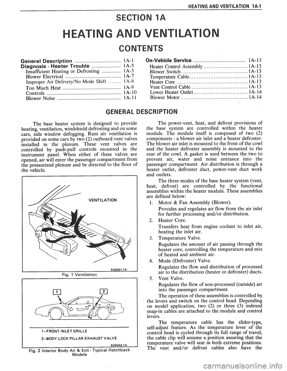
The base heater system is designed to provide
heating, ventilation, windshield defrosting and on some
cars, side window defogging. Ram air ventilation is
provided on some cars by two (2) outboard vent valves
installed in the plenum. These vent valves are
controlled by push-pull controls mounted in the
instrument panel. When either of these valves are
opened, air will enter the passenger compartment from
the pressurized plenum and be directed to the floor of
the vehicle.
/& VENTILATION
1-FRONT INLET GRILLE
2-BODY LOCK PILLAR EXHAUST VALVE
Fig. 2 Interior Body Air & Exit - Typical Hatchback Models
The power-vent, heat, and defrost provisions of
the base system are controlled within the heater
module. The module itself is composed of two (2)
components
- a blower air inlet and a heater defroster.
The blower air inlet is mounted to the front of the cowl
and the heater defroster assembly is mounted to the
rear of the cowl. A gasket is used between the two to
prevent air, water and noise entrance into the
passenger compartment. Air distribution is through a
heater outlet, defroster duct, power-vent duct work
and outlets.
The three modes of the base heater system (vent,
heat, defrost) are controlled by the functional
assemblies within the heater module. These assemblies
are defined below:
1. Motor & Fan Assembly (Blower).
Provides and regulates air flow from the air inlet
for further processing and/or distribution.
2. Heater Core.
Transfers heat from engine coolant to inlet air,
heating the inlet air.
3. Temperature Valve.
Regulates the amount of air passing through the
heater core, controlling the temperature and mix
of heated and ambient air.
4. Mode (Defroster) Valve.
Regulates the flow and distribution of processed
air to the distribution (heater or defroster) ducts.
5. Vent Valve.
Regulates the flow of non-processed (outside) air
into the passenger compartment.
The operation of these assemblies is controlled by
the levers and switch on the control head. Depending
on model application, two (2) or three
(3) indexed
snap-in cables are attached to the module and control
levers.
The temperature cable has the slider-type,
self-adjust feature. As the temperature lever of the
control head is cycled through its full range of travel,
the cable clip will assume a position assuring that the
temperature valve will seat in both extreme positions.
The vent and/or defrost cables also have the
Page 25 of 1825
1A-2 HEATING AND VENTILATION
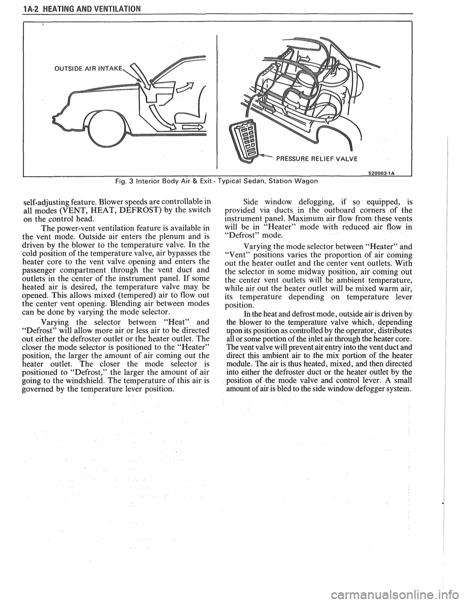
520003-1 A
Fig. 3 Interior Body Air & Exit - Typical Sedan, Station Wagon
self-adjusting feature. Blower speeds are controllable in
all modes (VENT, HEAT, DEFROST) by the switch
on the control head.
The power-vent ventilation feature is available in
the vent mode. Outside air enters the plenum and is
driven by the blower to the temperature valve. In the
cold position of the temperature valve, air bypasses the
heater core to the vent valve opening and enters the
passenger compartment through the vent duct and
outlets
in the center of the instrument panel. If some
heated air is desired, the temperature valve may be
opened. This allows mixed (tempered) air to flow out
the center vent opening. Blending air between modes
can be done by varying the mode selector.
Varying the selector between "Heat" and
"Defrost" will allow more air or less air to be directed
out either the defroster outlet or the heater outlet. The
closer the mode selector is positioned to the "Heater"
position, the larger the amount of air coming out the
heater outlet. The closer the mode selector is
positioned to "Defrost," the larger the amount of air
going to the windshield. The temperature of this air is
governed by the temperature lever position. Side window
defogging, if so equipped, is
provided via ducts in the outboard corners of the
instrument panel. Maximum air flow from these vents
will be in "Heater" mode with reduced air flow in
"Defrost" mode.
Varying the mode selector between "Heater" and
"Vent" positions varies the proportion of air coming
out the heater outlet and the center vent outlets. With
the selector in some midway position, air coming out
the center vent outlets will be ambient temperature,
while air out the heater outlet will be mixed warm air,
its temperature depending on temperature lever
position.
In the heat and defrost mode, outside air is driven by
the blower to the temperature valve which, depending
upon its position as controlled by the operator, distributes
all or some portion of the inlet air through the heater core.
The vent valve will prevent air entry into the vent duct and
direct this ambient air to the mix portion of the heater
module. The air is thus heated, mixed, and then directed
into either the defroster duct or the heater outlet by the
position of the mode valve and control lever.
A small
amount of air is bled to the side window defogger system.
Page 27 of 1825
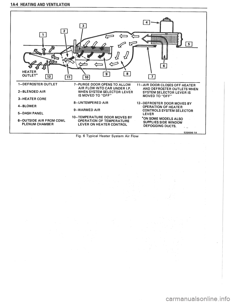
1A-4 HEATING AND VENTILATION
1-DEFROSTER OUTLET
7-PURGE DOOR OPENS TO ALLOW
11-AIR DOOR CLOSES OFF HEATER
AIR FLOW INTO CAR UNDER I.P.
AND DEFROSTER OUTLETS WHEN
2-BLENDED AIR WHEN SYSTEM SELECTOR LEVER SYSTEM SELECTOR LEVER IS
IS MOVED TO "OFF"
MOVED TO "OFF"
3-HEATER CORE
8-UNTEMPERED AIR
12-DEFROSTER DOOR MOVES BY
4-BLOWER OPERATION OF HEATER
9-WARMED AIR CONTROLS SYSTEM SELECTOR
5-DASH PANEL LEVER
10-TEMPERATURE DOOR MOVES BY
6-OUTSIDE AIR FROM COWL
OPERATION OF TEMPERATURE "ON
SOME MODELS ALSO
PLENUM CHAMBER
LEVER ON HEATER CONTROL SUPPLIES
SIDE WINDOW
DEFOGGING DUCTS.
. -.
Fig. 6 Typical Heater System Air Flow
Page 28 of 1825
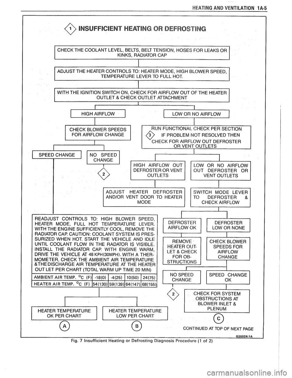
HEATING AND VENTILATION 1A-5
@ INSUFFICIENT HEATING OR DEFROST lNG
OF THE HEATER
IF PROBLEM
NOT RESOLVED THEN
HECK FOR AIRFLOW OUT DEFROSTER
VENT OUTLETS
INSTALL THE RADIATOR CAP. WITH ENGINE WARM,
DRIVE THE VEHICLE AT
48 KPH(3OMPH). WITH A THER-
MOMETER, CHECK THE AMBIENT AIR TEMPERATURE
CONTINUED AT TOP OF NEXT PAGE
Fig. 7 Insufficient Heating or Defrosting Diagnosis Procedure (7 of 2)
Page 29 of 1825
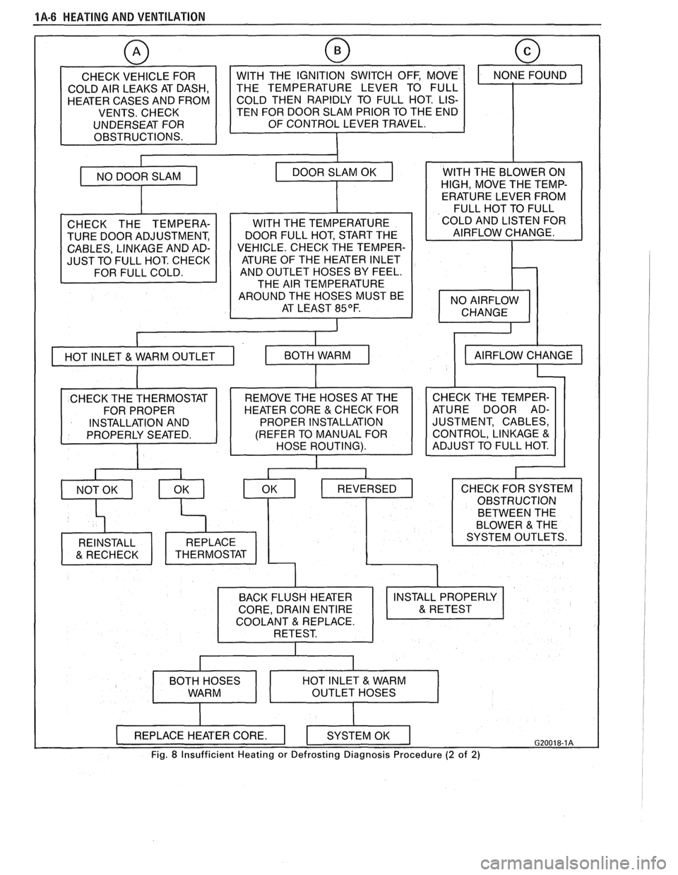
1A-6 HEATING AND VENTILATION
CHECK VEHICLE FOR
COLD AIR LEAKS AT DASH,
HEATER CASES AND FROM
VENTS. CHECK
UNDERSEAT FOR
OBSTRUCTIONS.
w
TEN FOR DOOR SLAM PRIOR TO THE END
CHECK THE TEMPERA-
TURE DOOR ADJUSTMENT,
CABLES, LINKAGE AND AD-
JUST TO FULL HOT. CHECK
I
WITH THE TEMPERATURE
DOOR FULL HOT, START THE
VEHICLE. CHECK THE TEMPER- ATURE OF THE HEATER INLET
AND OUTLET HOSES BY FEEL.
THE AIR TEMPERATURE
AROUND THE HOSES MUST BE AT LEAST
85OF.
I
WITH THE BLOWER ON
HIGH, MOVE THE TEMP-
ERATURE LEVER FROM
FULL HOT TO FULL
COLD AND LISTEN FOR
AIRFLOW CHANGE.
CHECK THE TEMPER-
ATURE DOOR AD-
JUSTMENT, CABLES,
CONTROL, LINKAGE
&
BETWEEN THE
COOLANT REPLACE.
Fig. 8 Insufficient Heating or Defrosting Diagnosis Procedure (2 of 2)
Page 30 of 1825
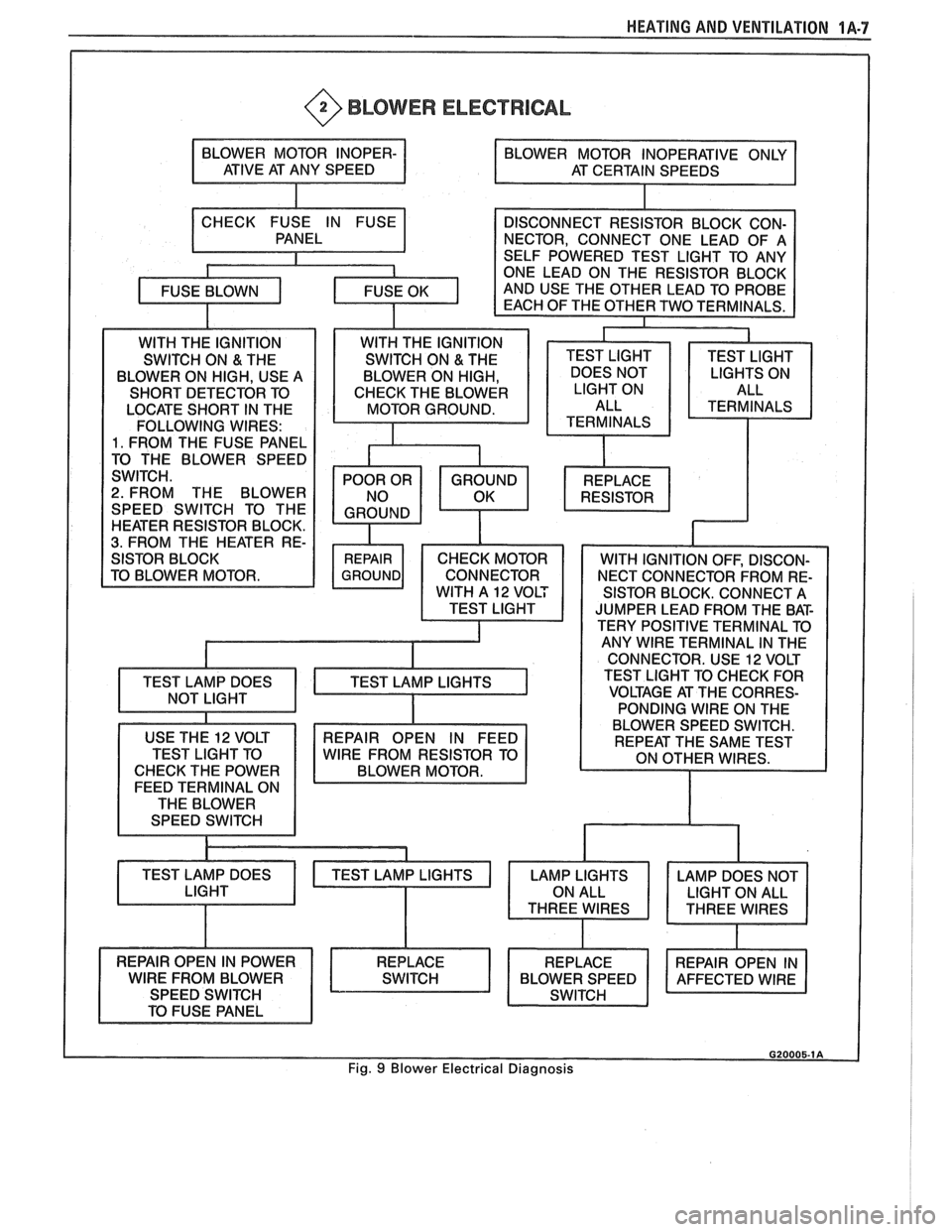
HEATING AND VENTILATION 1A-7
@ BLOWER ELECTRICAL
LOCATE SHORT IN THE
FOLLOWING WIRES:
1. FROM THE FUSE PANEL
2. FROM THE BLOWER
SPEED SWITCH TO THE
HEATER RESISTOR BLOCK.
3. FROM THE HEATER RE-
SISTOR BLOCK. CONNECT A
JUMPER LEAD FROM THE BAT-
TERY POSITIVE TERMINAL TO
ANY
WlRE TERMINAL IN THE
CONNECTOR. USE
12 VOLT
TEST LIGHT TO CHECK FOR
VOLTAGE AT THE CORRES-
PONDING WIRE ON THE
USE THE
12 VOLT
TEST LIGHT TO
CHECK THE POWER
FEED TERMINAL ON
THE BLOWER
SPEED SWITCH
TEST LAMP DOES BLOWER
SPEED SWITCH.
REPAIR OPEN IN FEED
WlRE FROM RESISTOR TO
BLOWER MOTOR.
Fig. 9 Blower Electrical Diagnosis