1988 PONTIAC FIERO battery capacity
[x] Cancel search: battery capacityPage 444 of 1825

BATTERY 6D1.1
SECTION 6Dl
BATTERY
CONTENTS
.......................... .. General Description ................................ 6D1- 1 Battery Charging ...... 6D 1-2
Battery .......................... ... ....................... 6D 1 - 1 Charging Completely Discharged
.................................................... ............................. Ratings .................... ... 6D 1 - 1 Battery 6D 1-3
........................................... Reserve Capacity ..................................... 6D 1 - 1 Jump Starting 6D
1-4
Cranking ............a*............ 6D1-1 On-Gar Service ...................................... 6Dl-5 .................................. Built-In Hydrometer 6D 1-2 Battery Cable Routing ............................... 6D 1-5 Diagnosis ................................................... 6Dl-2
Specifications .............................................. 6D 1-7 ............................. Service Procedures ..... 6D 1-2
GENERAL DESCRIPTION
The engine electrical system includes the battery,
ignition (primary and secondary), starter (and related
wiring) and the generator (and related wiring).
Diagnostic charts (see Section 6D) will aid in
trouble-shooting system faults. When a fault is traced
to a particular component, refer to that components'
section of the service manual.
BATTERY
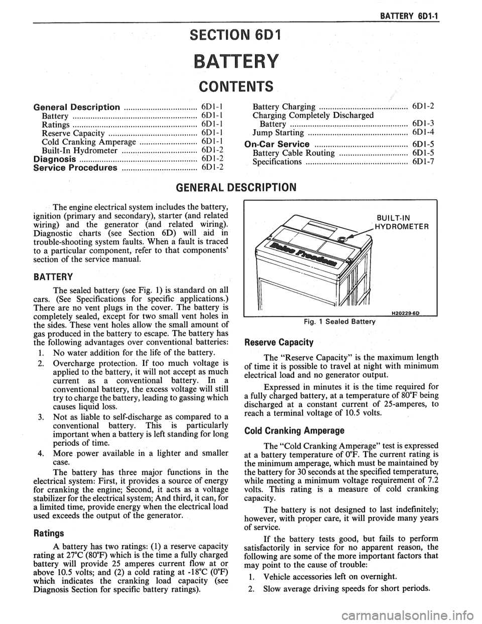
The sealed battery (see Fig. 1) is standard on all
cars. (See Specifications for specific applications.)
There are no vent plugs in the cover. The battery is
completely sealed, except for two small vent holes in
the sides. These vent holes allow the small amount of
gas produced in the battery to escape. The battery has
the following advantages over conventional batteries:
1. No water addition for the life of the battery.
2. Overcharge protection. If too much voltage is
applied to the battery, it will not accept as much
current as a conventional battery. In a
conventional battery, the excess voltage will still
try to charge the battery, leading to gassing which
causes liquid loss.
3. Not as liable to self-discharge as compared to a
conventional battery. This is particularly
important when a battery is left standing for long
periods of time.
4. More power available in a lighter and smaller
case.
The battery has three major functions in the
electrical system: First, it provides a source of energy
for cranking the engine; Second, it acts as a voltage
stabilizer for the electrical system; And third, it can, for
a limited time, provide energy when the electrical load
used exceeds the output of the generator.
Ratings
A battery has two ratings: (1) a reserve capacity
rating at 27°C (80°F) which is the time a fully charged
battery will provide 25 amperes current flow at or
above 10.5 volts; and (2) a cold rating at -18°C (0°F)
which indicates the cranking load capacity (see
Diagnosis Section for specific battery ratings).
BUILT-IN
HYDROMETER
Fig. 1 Sealed Battery
Reserve Capacity
The "Reserve Capacity" is the maximum length
of time it is possible to travel at night with minimum
electrical load and no generator output.
Expressed in minutes it is the time required for
a fully charged battery, at a temperature of 80°F being
discharged at a constant current of 25-amperes, to
reach a terminal voltage of 10.5 volts.
Cold Cranking Amperage
The "Cold Cranking Amperage" test is expressed
at a battery temperature of
0°F. The current rating is
the minimum amperage, which must be maintained by
the battery for 30 seconds at the specified temperature,
while meeting a minimum voltage requirement of 7.2
volts. This rating is a measure of cold cranking
capacity.
The battery is not designed to last indefinitely;
however, with proper care, it will provide many years
of service.
If the battery tests good, but fails to perform
satisfactorily in service for no apparent reason, the
following are some of the more important factors that
may point to the cause of trouble:
1. Vehicle
accessories left on overnight.
2. Slow
average driving speeds for short periods.
Page 446 of 1825

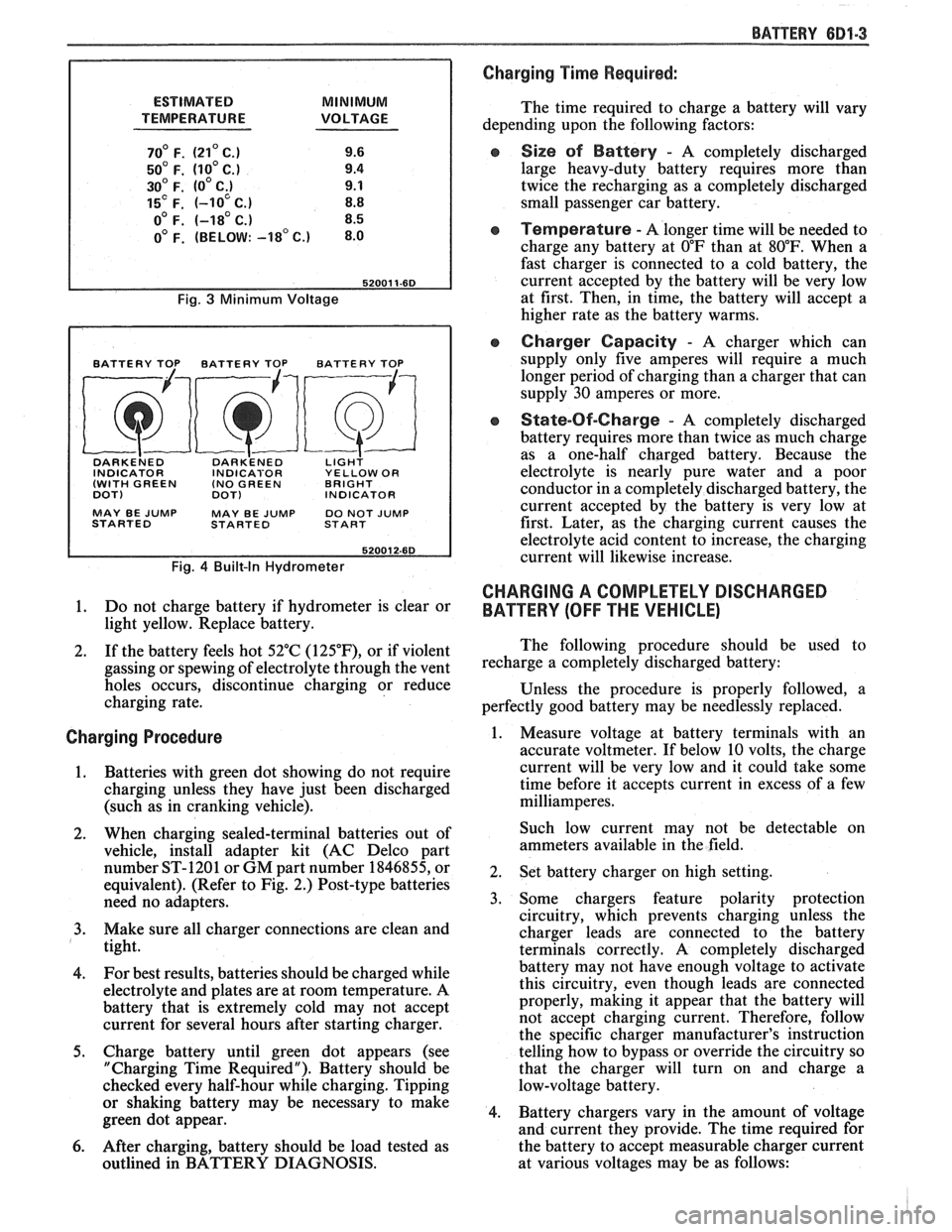
ESTIMATED MINIMUM
TEMPERATURE VOLTAGE
70' F. (21' C.) 9.6
50' F. (10' C.) 9.4
30' F. (0' C;) 9.1
15' F. (-10 C.) 8.8
o0 F. (-18' C.) 8.5
0' F. (BELOW: -18' c.) 8.0
Fig. 3 Minimum Voltage
BATTERY TOP BATTERY TOP BATTERY TOP
DARKE~ED DARK'ENED LIGH? INDICATOR INDICABOR YELLOW OR
(WITH GREEN (NO
GREEN BRIGHT
DOT)
DOT) INDICATOR
MAY BE
JUMP MAY BE JUMP DO NOT JUMP
STARTED STARTED START
Fig. 4 Built-In Hydrometer
1. Do not charge battery if hydrometer is clear or
light yellow. Replace battery.
2. If the battery feels hot 52°C
(125"F), or if violent
gassing or spewing of electrolyte through the vent
holes occurs, discontinue charging or reduce
charging rate.
Charging Procedure
1. Batteries with green
dot showing do not require
charging unless they have just been discharged
(such as in cranking vehicle).
2. When charging sealed-terminal batteries out of
vehicle, install adapter kit (AC Delco part
number ST-1201 or GM part number 1846855, or
equivalent). (Refer to Fig. 2.) Post-type batteries
need no adapters.
3. Make sure all charger connections are clean and
tight.
4. For
best results, batteries should be charged while
electrolyte and plates are at room temperature. A
battery that is extremely cold may not accept
current for several hours after starting charger.
5. Charge battery until green dot appears (see
"Charging Time Required"). Battery should be
checked every half-hour while charging. Tipping
or shaking battery may be necessary to make
green dot appear.
6. After charging, battery should be load tested as
outlined in BATTERY DIAGNOSIS.
BATTERY 681-3
Charging Time Required:
The time required to charge a battery will vary
depending upon the following factors:
e Size sf Battery - A completely discharged
large heavy-duty battery requires more than
twice the recharging as a completely discharged
small passenger car battery.
Temperature - A longer time will be needed to
charge any battery at
O"F than at 80°F. When a
fast charger is connected to a cold battery, the
current accepted by the battery will be very low
at first. Then, in time, the battery will accept a
higher rate as the battery warms.
Charger Capacity - A charger which can
supply only five amperes will require a much
longer period of charging than a charger that can
supply
30 amperes or more.
e State-Of-Charge - A completely discharged
battery requires more than twice as much charge
as a one-half charged battery. Because the
electrolyte is nearly pure water and a poor
conductor in a completely discharged battery, the
current accepted by the battery is very low at
first. Later, as the charging current causes the
electrolyte acid content to increase, the charging
current will likewise increase.
CHARGING A COMPLETELY DISCHARGED
BATTERY
(OFF THE VEHICLE)
The following procedure should be used to
recharge a completely discharged battery:
Unless the procedure is properly followed, a
perfectly good battery may be needlessly replaced.
1. Measure voltage at battery terminals with an
accurate voltmeter. If below 10 volts, the charge
current will be very low and it could take some
time before it accepts current in excess of a few
milliamperes.
Such low current may not be detectable on
ammeters available in the field.
2. Set battery charger on high setting.
3. Some chargers feature polarity protection
circuitry, which prevents charging unless the
charger leads are connected to the battery
terminals correctly. A completely discharged
battery may not have enough voltage to activate
this circuitry, even though leads are connected
properly, making it appear that the battery will
not accept charging current. Therefore, follow
the specific charger manufacturer's instruction
telling how to bypass or override the circuitry so
that the charger will turn on and charge a
low-voltage battery.
4. Battery chargers vary in the amount of voltage
and current they provide. The time required for
the battery to accept measurable charger current
at various voltages may be as follows:
Page 447 of 1825

6D1-4 BATTERY
VOLTAGE
A. 16.0 or more
B. 14.0
- 15.9
C. 13.9 or less HOURS
1. Set parking brake and place automatic
Up to 4 Hours transmission in "PARK" (NEUTRAL for
Up to 8 Hours manual transmission.) Turn off the ignition,
Up to 16 Hours turn off lights, and all other electrical
If the charge current is still not
measurable
at the end of the above charging
times, the battery should be replaced.
If the charge current is measurable during
the charging time, the battery is considered to be
good and charging should be completed in the
normal manner.
5. It
is important to remember that a completely
discharged battery must be recharged for a
sufficient number of ampere hours (AH) to
restore it to a usable state. As a general rule of
thumb, using the reserve capacity rating (RC) of
the battery as the number of ampere hours of
charge will usually bring the green dot into view.
For example, if battery is rated at 75 RC minutes,
it would be completely recharged as follows:
10 ampere charge x 7-1/2 hours
= 75 AH
25 ampere charge x 3 hours = 75 AH, etc.
6. It
is recommended that any battery recharged by
this procedure be
LOAD TESTED to establish
serviceability.
JUMP STARTING IN CASE OF EMERGENCY
WITH AUXILIARY (BOOSTER) BAVEEWY
NOTICE: Do not push or tow the vehicle to start.
Damage to the emission system, or to other parts
of the vehicle may result.
Both booster and discharged battery should be
treated carefully when using jumper cables. Follow the
procedure outlined below, being careful not to cause
sparks:
CAUTION: Departure from these
conditions or the procedure below
could result in:
(1) Serious personal
injury (particularly to eyes) or property
damage from such causes as battery
explosion, battery acid, or electrical
burns; and/or
(2) damage to electronic
components of either vehicle.
Never expose battery to open flame or electric
spark
- batteries generate a gas which is flammable and
explosive.
Remove rings, watches, and other jewelry. Wear
approved eye protection.
Do not allow battery fluid to contact eyes, skin,
fabrics, or painted surfaces
- fluid is a corrosive acid.
Flush any contacted area with water immediately and
thoroughly. Be careful that metal tools or jumper
cables do not contact the positive battery terminal (or
metal in contact with it) and any other metal on the
car, because a short circuit could occur. Batteries
should always be kept out of the reach of children.
loads.
2. Check the built-in hydrometer. If it is clear or
light yellow, replace the battery.
3. Attach the end of one jumper cable to the positive
terminal of the booster battery and the other end
of the same cable to the positive terminal of the
discharged battery. Do not permit vehicles to
touch each other as this could cause a ground
connection and counteract the benefits of this
procedure. (Use 12-volt battery only to jump start
the engine).
4. Attach one end of the remaining negative cable
to the negative terminal of the booster battery,
and the other end to a solid engine ground (such
as
A/C compresser bracket or generator
mounting bracket) at least 18 inches from the
battery of the vehicle being started (DO NOT
CONNECT DIRECTLY TO THE NEGATIVE
TERMINAL OF THE DEAD BATTERY).
5. Start the engine of the vehicle that is providing
the jump start and turn off electrical accessories.
Then start the engine in the car with the
discharged battery.
6. Reverse these directions exactly when removing
the jumper cables. The negative cable must be
disconnected from the engine that was jump
started first.
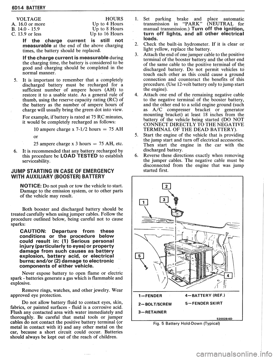
I-FENDER 4-BATTERY (REF.)
2- BOLTISCREW 5-FENDER SKIRT
3-RETAINER
520028-60
Fig. 5 Battery Hold-Down (Typical)
Page 974 of 1825

DRIVEABILIW AND EMISSIONS - FUEL INJECTION 6E-13
When the voltage to the solenoid is turned off, (de-
energized), a spring raises the plunger.
ESC - ELECTRONIC SPARK CONTROL - Used to
sense detonation and retard spark advance when
detonation occurs.
EST - ELECTRONIC SPARK TIMING - ECM
controlled timing of ignition spark.
EVRV - ELECTRONIC VACUUM REGULAWR
VALVE - Controls EGR vacuum.
FED - FEDEWL - VehicleIEngine available in all
states except California.
GROUND - The negative (-) side of the battery.
Also could be a wire (conductor) shorted to ground.
HC - HYDROCARBONS - One of the pollutants
found in engine exhaust.
HIGH IMPEDANCE VOLTMETER - Mas high
opposition to the flow of electrical current.
Good for
reading circuits with low current flow, such as found
in electronic systems because it allows tests to be
made without affecting the circuit.
HE1 - HIGH ENERGY IGNITION - A distributor that
uses an electronic module and pick-up coil in place of
contact points.
Hg - MERCURY - A calibration material used as a
standard for vacuum measurement.
IAC - IDLE AIR CONTROL - A valve installed in the
throttle body of fuel injected systems and controlled by
the ECM to regulate idle speed.
IDEAL MIXWRE - The airlfuel ratio which provides
the best performance, while maintaining maximum
conversion of exhaust emissions. Typically it is
14.7:1.
ID1 - INTEGRATED DIRECT IGNITION - Produces the
ignition spark without the aid of an ignition
distributor or spark plug wires.
IDLE AIR BLEED VALVE - Controls the amount of
air let into the idle fuel mixture prior to the mixture
entering the carburetor idle system, when the
MIC
solenoid is energized.
ILC - IDLE LOAD COMPENSATOR - Device used to
control throttle angle during long deceleration, such
as coasting down a long grade; it extends at wide open
throttle position or to prevent engine stalls at idle.
INPUTS - Information from sources (such as
coolant temperature sensors, exhaust oxygen sensor,
etc.) to the ECM that indicate how the systems are
performing.
INTERMITTENT - Occurs now and then; not
continuously. In electrical circuits, refers to
occasional open, short, or ground.
I.P. - INSTRUMENT PANEL
ISC - IDLE SPEED CONTROL - Regulates throttle
valve position to control idle speed. Idle speed is
controlled by the ECM and is not adjustable.
KMIHR - KILOMEnR PER HOUR - A metric unit
measuring speed needed to travel distance of one
kilometer (1000 meters) in one hour.
L - LITER - A metric unit of capacity.
L4 - FOUR CYLINDER IN-LINE ENGINE
MAF - MASS AIR FLOW - Sensor which measures
the amount of air entering the engine.
MALFUNCTION - A problem that causes the
system to operate incorrectly. Typical malfunctions
are wiring harness opens or shorts, failed sensors or
circuit components.
MANIFOLD VACUUM SENSOR - Indicates vacuum
in the intake manifold by measuring the pressure in
intake manifold in relation to barometric pressure. It
is also called a differential pressure sensor because
it
measures the difference between the two pressures. It
puts out a voltage which is highest when the vacuum
is highest. The maximum voltage is between 4 and 5
volts.
MAP - MANIFOLD ABSOLUTE PRESSURE SENSOR -
Reads pressure changes in intake manifold with
reference to zero pressure. It puts out a voltage which
is highest when the pressure is highest. The
maximum voltage is between
4 and 5 volts.
MAT - Manifold Air Temperature Sensor.
Measures temperature of air in the intake manifold.
MIC - MIXTURE CONTROL
MEM-CAL
- MEMORY CALIBRATOR - Contains
specific calibrations to meet the requirements of a
specific engine.
MFI - MULTlPORT FUEL INJECnON - Individual
injectors for each cylinder are mounted in the intake
manifold. The injectors are fired in groups rather than
individually.
MIXTURE CONTROL (MIC) SOLENOID - Device,
installed in carburetor, to regulate the airlfuel ratio.
MODE - A particular state of operation.
MPH - MILES PER HOUR - A unit measuring speed
needed to travel distance of one mile (5280 feet) in one
hour.
N.C. - NORMALLY CLOSED - State of relay contacts
or solenoid plunger when no voltage is applied.
N-rn - NEWTON METER (Torque) - A metric unit
describing force.