1988 PONTIAC FIERO mirror controls
[x] Cancel search: mirror controlsPage 1166 of 1825

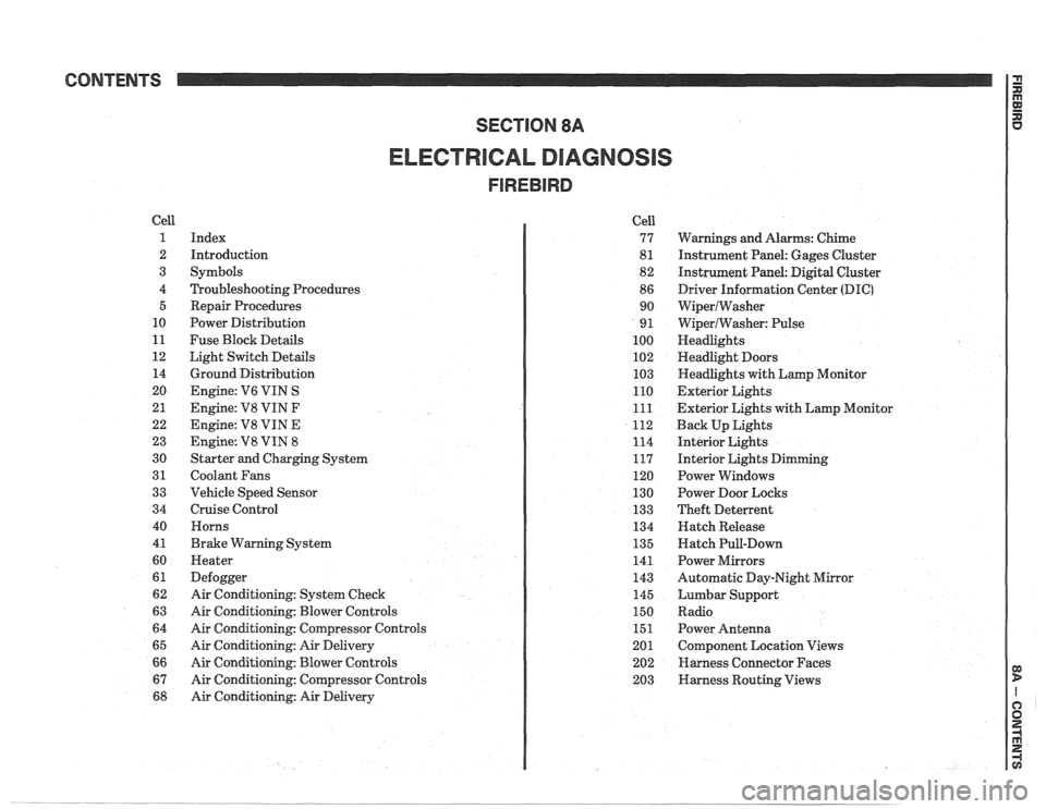
CONTENTS
ELECTRICAL DIAGNOSIS
Cell
1
2
3
4 5
10
11
12 14
20
21
22
23
30
31
33
34
40
4
1
60
61
62
63
64
65
66
67
68
Index
Introduction
Symbols
Troubleshooting Procedures Repair Procedures
Power Distribution
Fuse Block Details
Light Switch Details
Ground Distribution
Engine:
V6 VIN S
Engine: V8 VIN
F
Engine: V8 VIN E
Engine:
V8 VIN 8
Starter and Charging System
Coolant Fans
Vehicle Speed Sensor
Cruise Control Horns
Brake Warning System
Heater
Defogger
Air Conditioning: System Check
Air Conditioning: Blower Controls
Air Conditioning: Compressor Controls
Air Conditioning: Air Delivery
Air Conditioning: Blower Controls
Air Conditioning: Compressor Controls
Air Conditioning: Air Delivery Cell
77
8
1
82
86 90
9
1
100
102
103
110
111
112
114
117
120
130
133
134
135
141
143
145
150
151
201 202
203
Warnings and Alarms: Chime
Instrument Panel: Gages Cluster
Instrument Panel:
Digital Cluster
Driver Information Center
(DIC)
WiperlWasher
WiperlWasher: Pulse
Headlights
Headlight Doors
Headlights with Lamp Monitor
Exterior Lights
Exterior Lights with Lamp Monitor
Back Up Lights
Interior Lights
Interior Lights Dimming
Power Windows
Power Door Locks
Theft Deterrent
Hatch Release
Hatch Pull-Down
Power Mirrors
Automatic Day-Night Mirror
Lumbar Support
Radio Power Antenna
Component Location Views
Harness Connector Faces
Harness Routing Views
Page 1714 of 1825

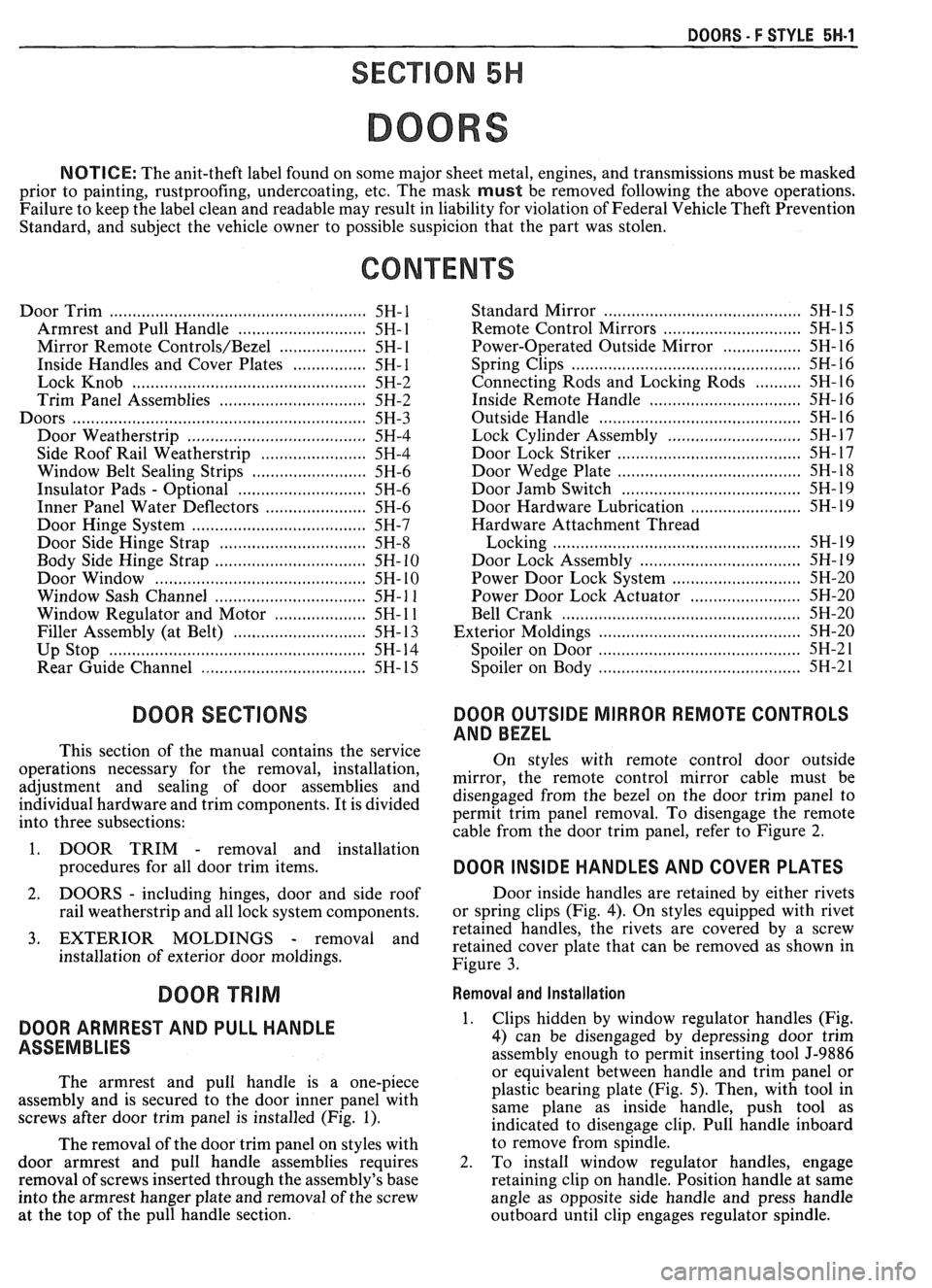
DOORS - F STYLE 5H-1
SEC"610N 5H
DOORS
NOTICE: The anit-theft label found on some major sheet metal, engines, and transmissions must be masked
prior to painting, rustproofing, undercoating, etc. The mask
must be removed following the above operations.
Failure to keep the label clean and readable may result in liability for violation of Federal Vehicle Theft Prevention
Standard, and subject the vehicle owner to possible suspicion that the part was stolen.
Door Trim
...................................................... 5H- 1
Armrest and Pull Handle .......................... 5H- 1
Mirror Remote Controls/Bezel ................... 5H- 1
Inside Handles and Cover Plates ................ 5H- 1
Lock Knob .................................... .... ........... 5H-2
Trim Panel Assemblies .............................. 5H-2
Doors ............................................................ 5H-3
Door Weatherstrip ....................................... 5H-4
Side Roof Rail Weatherstrip ....................... 5H-4
Window Belt Sealing Strips ......................... 5H-6
Insulator Pads - Optional ............................ 5H-6
Inner Panel Water Deflectors ...................... 5H-6
Door Hinge System .................................. .... 5H-7
Door Side Hinge Strap ............................... 5H-8
Body Side Hinge Strap ................................ 5H- 10
Door Window ..................... .. ................... 5H- 10
Window Sash Channel ................................. 5H- 1 1
Window Regulator and Motor .................... 5H- 1 1
Filler Assembly (at Belt) ......................... ... . 5H- 13
Up Stop ............................ .. ...................... 5H- 14
Rear Guide Channel .................................... 5H- 15
DOOR SECnONS
This section of the manual contains the service
operations necessary for the removal, installation,
adjustment and sealing of door assemblies and
individual hardware and trim components. It is divided
into three subsections:
1. DOOR TRIM
- removal and installation
procedures for all door trim items.
2. DOORS - including hinges, door and side roof
rail weatherstrip and all lock system components.
3. EXTERIOR MOLDINGS - removal and
installation of exterior door moldings. Standard Mirror
......................................... 5H- 15
........................... Remote
Control Mirrors 5H- 15
Power-Operated Outside Mirror ................. 5H-16
Spring Clips .................................................. 5H- 16
Connecting Rods and Locking Rods .......... 5H-16
Inside Remote Handle ................................ 5H- 16
......................................... Outside Handle 5H- 16
............................. Lock Cylinder Assembly 5H- 17
...................................... Door Lock Striker 5H- 17
....................................... Door Wedge Plate 5H- 18
....................................... Door Jamb Switch 5H- 19
........................ Door Hardware Lubrication 5H- 19
Hardware Attachment Thread
.................................................. Locking 5H- 19
................................... Door Lock Assembly 5H- 19
............................ Power Door Lock System 5H-20
........................ Power Door Lock Actuator 5H-20
............. .................................... Bell Crank ... 5H-20
.......................................... Exterior Moldings 5H-20
.......................................... Spoiler on Door 5H-21
.......................................... Spoiler on Body 5H-2 1
DOOR OUTSIDE MIRROR REMOTE CONTROLS
AND BEZEL
On styles with remote control door outside
mirror, the remote control mirror cable must be
disengaged from the bezel on the door trim panel to
permit trim panel removal. To disengage the remote
cable from the door trim panel, refer to Figure
2.
DOOR INSIDE HANDLES AND COVER PLATES
Door inside handles are retained by either rivets
or spring clips (Fig.
4). On styles equipped with rivet
retained handles, the rivets are covered by a screw
retained cover plate that can be removed as shown in
Figure
3.
DOOR TRIM Removal and Installation
DOOR ARMREST AND PULL HANDLE 1.
ASSEMBLIES
The armrest and pull handle is a one-piece
assembly and is secured to the door inner panel with
screws after door trim panel is installed (Fig. 1). Clips hidden
by window regulator handles (Fig,
4) can be disengaged by depressing door trim
assembly enough to permit inserting tool J-9886
or equivalent between handle and trim panel or
plastic bearing plate (Fig.
5). Then, with tool in
same plane as inside handle, push tool as
indicated to disengage clip. Pull handle inboard
The removal of the door trim panel on styles with to
remove from
s$n>le. -
door armrest and pull handle assemblies requires 2. To install window regulator handles, engage
removal of screws inserted through the assembly's base retaining clip on handle. Position handle at same
into the armrest hanger plate and removal of the screw angle as opposite side handle and press handle
at the top of the pull handle section.
outboard until clip engages regulator spindle.
Page 1716 of 1825

BOORS - F STYLE 5H-3
I
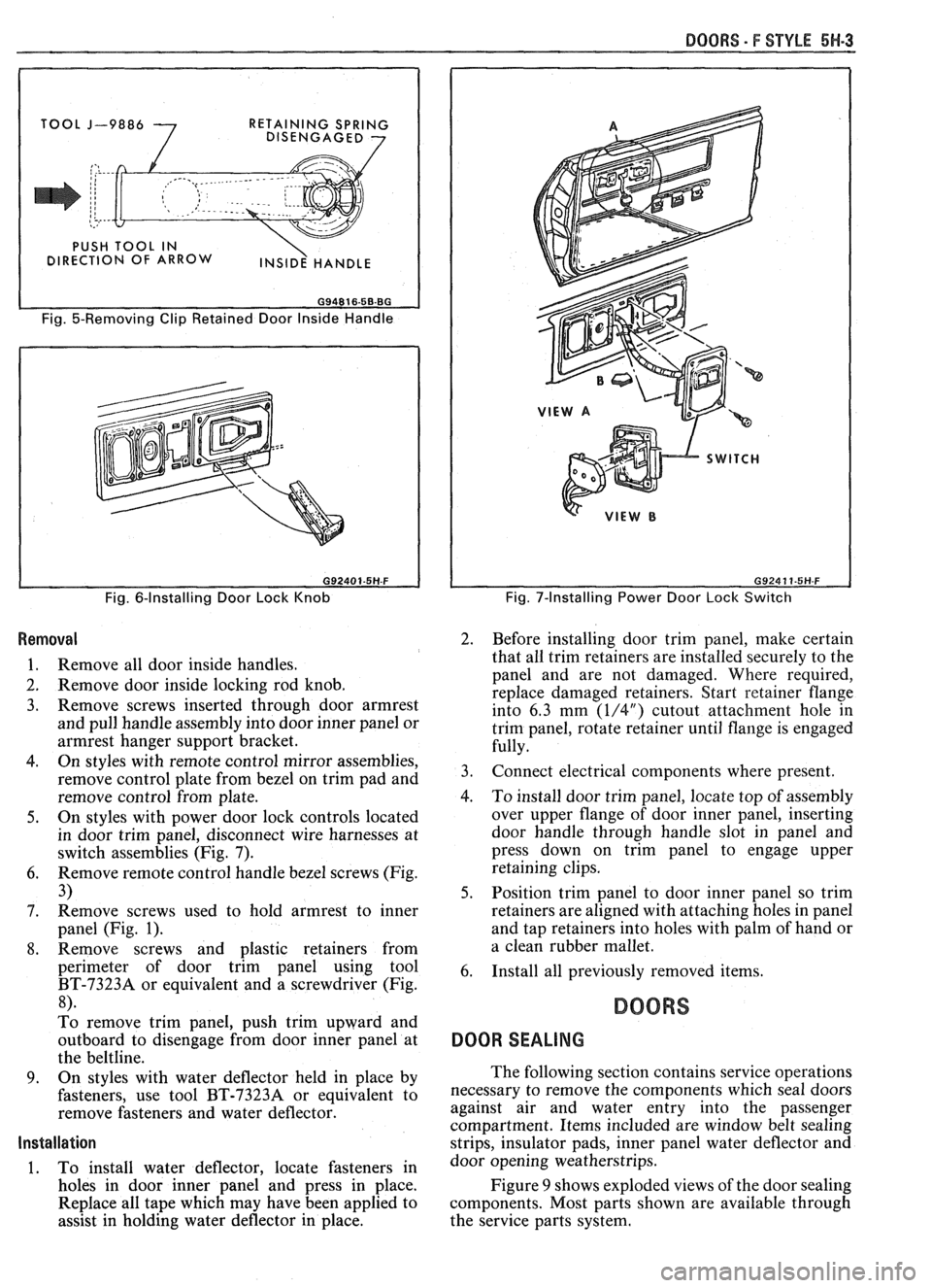
J-9886
7
RETAINING SPRING
DISENGAGED 7
Fig. 5-Removing Clip Retained Door Inside Handle
Fig. 6-Installing Door Lock Knob
Removal
1. Remove all door inside handles.
2. Remove door inside locking rod knob.
3. Remove screws inserted through door armrest
and pull handle assembly into door inner panel or
armrest hanger support bracket.
4. On styles with remote control mirror assemblies,
remove control plate from bezel on trim pad and
remove control from plate.
5. On styles with power door lock controls located
in door trim panel, disconnect wire harnesses at
switch assemblies (Fig. 7).
6. Remove remote control handle bezel screws (Fig.
3)
7. Remove
screws used to hold armrest to inner
panel (Fig.
1).
8. Remove screws and plastic retainers from
perimeter of door trim panel using tool
BT-73238 or equivalent and a screwdriver (Fig.
8).
To remove trim panel, push trim upward and
outboard to disengage from door inner panel at
the beltline.
9. On styles with water deflector held in place by
fasteners, use tool BT-7323A or equivalent to
remove fasteners and water deflector.
Installation
1. To install water deflector, locate fasteners in
holes in door inner panel and press in place.
Replace all tape which may have been applied to
assist in holding water deflector in place.
Fig. 7-Installing Power Door Lock Switch
2. Before installing door trim panel, make certain
that all trim retainers are installed securely to the
panel and are not damaged. Where required,
replace damaged retainers. Start retainer Range
into 6.3 mm
(1/4") cutout attachment hole in
trim panel, rotate retainer until flange is engaged
fully.
3. Connect electrical components where present.
4. To install door trim panel, locate top of assembly
over upper flange of door inner panel, inserting
door handle through handle slot in panel and
press down on trim panel to engage upper
retaining clips.
5. Position trim panel to door inner panel so trim
retainers are aligned with attaching holes in panel
and tap retainers into holes with palm of hand or
a clean rubber mallet.
6. Install all previously removed items.
BOORS
DOOR SEALING
The following section contains service operations
necessary to remove the components which seal doors
against air and water entry into the passenger
compartment. Items included are window belt sealing
strips, insulator pads, inner panel water deflector and
door opening weatherstrips.
Figure
9 shows exploded views of the door sealing
components. Most parts shown are available through
the service parts system.