1988 PONTIAC FIERO wiper fluid
[x] Cancel search: wiper fluidPage 1440 of 1825

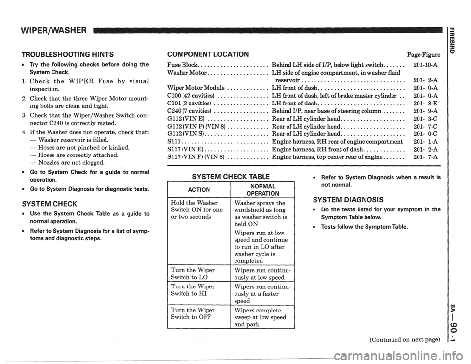
TROUBLESHOOTING HINTS
0 Try the following checks before doing the
System Check.
1. Check the WIPER Fuse by visual
inspection.
2. Check that the three Wiper Motor mount-
ing bolts are clean and tight.
3. Check that the Wiper/Washer Switch con-
nector C240 is correctly mated.
4. If the Washer does not operate, check that:
- Washer reservoir is filled.
- Hoses are not pinched or kinked.
- Hoses are correctly attached.
- Nozzles are not clogged.
r Go to System Check for a guide to, normal
operation.
0 Go to System Diagnosis for diagnostic tests.
SYSTEM C H EGK
Use the System Check Table as a guide to
normal operation.
Refer to System Diagnosis for a list of symp-
toms and diagnostic steps.
COMPONENT LOCATION Page-Figure
...... ..................... Fuse Block. Behind LH side of IIP, below light switch.
Washer Motor.
.................. LH side of engine compartment, in washer fluid
reservoir
................................
.......................... Wiper Motor Module ............. LH front of dash.
.. Cl00 (42 cavities) ................ LH front of dash, left of brake master cylinder
.......................... C101 (3 cavities) ................. LH front of dash.
....... C240 (7 cavities) ................. Behind IIP, near base of steering column
................... 6112 (VIN E) ................... Rear of LH cylinder head.
................... 6112 (VIN F) (VIN 8) ............. Rear of LH cylinder head.
................... 6112 (VIN S) .................... Rear of LW cylinder head.
Slll ........................... Engine harness, RH rear of engine compartment
............ S117 (VIN E) .................... Engine harness, RH front of dash.
...... S117 (VIN F) (VIN 8) ............. Engine harness, top center rear of engine.
SYSTEM CHECK TABLE Refer to System Diagnosis when a result is
not normal.
SYSTEM DIAGNOSIS
0 Do the tests listed for your symptom in the
Symptom Table below.
0 Tests follow the Symptom Table.
or two seconds
Wipers run at low
(Continued on next page)
. __- ______ --___ -..- .
Page 1444 of 1825

WIPERIWASHER: PULSE, CD4 I G n
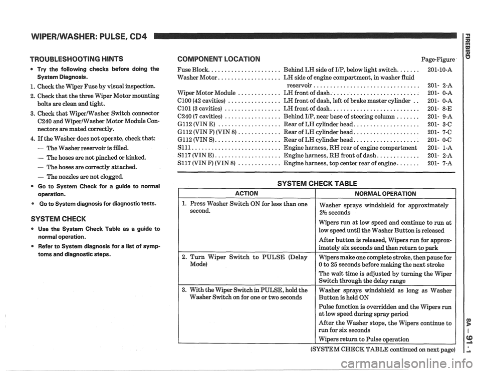
TROUBLESHOOTING HINTS
Try the following checks before doing the
System Diagnosis.
1. Check the Wiper Fuse by visual inspection.
2. Check that the three
VViper Motor mounting
bolts are clean and tight.
3. Check that Wipermasher Switch connector
C240 and WiperIWasher Motor Module Con-
nectors are mated correctly.
4. If the Washer does not operate, check that:
- The Washer reservoir is filled.
- The hoses are not pinched or kinked.
- The hoses are correctly attached.
- The nozzles are not clogged.
Go to System Check for a guide to normal
operation.
Go to System diagnosis for diagnostic tests.
SYSTEM CHECK
Use the System Check Table as a guide to
normal operation.
e Refer to System diagnosis for a list of symp-
toms and diagnostic steps.
COMPONENT LOCATION Page-Figure
...... ..................... Fuse Block. Behind LR side of IIP, below light switch.
.................. Washer Motor. LH side of engine compartment, in washer fluid
reservoir
................................
.......................... ............. Wiper Motor Module LN front of dash.
.. C100 (42 cavities) ................ LR front of dash, left of brake master cylinder
.......................... C101(3 cavities) ................. LH front of dash.
....... C240 (7 cavities) ................. Behind IIP, near base of steering column
................... 6112 (VIN E) ................... Rear of LN cylinder head.
................... 6112 (VIN F) (VIN 8) ............. Rear of LN cylinder head.
................... 6112 (VIN S) .................... Rear of LH cylinder head.
S111 ........................... Engine harness, RN rear of engine compartment
............ S117 (VINE) .................... Engine harness, RN front of dash.
...... S117 (VIN F) (VIN 8) ............. Engine harness, top center rear of engine.
SYSTEM CHECK TABLE
Wipers run at low speed and continue to run at
low speed until the Washer Button is released
Pulse function is overridden and the Wipers
run
After the Washer stops, the Wipers continue to
run for six seconds
I Wipers return to Pulse operation
(SYSTEM
CHECK TABLE continued on next page)
Page 1628 of 1825

WINDSI4IELD WIPER SYSTEMS - F CARLINE 8E -1
SECTION 8E
F CARL
ELD W PER-WASHER SYSTEM
PULSE & STANDARD
CONTENTS
General Description ....................... 8E -1 Park Switch Replacement ............... .8E -3
Wiper and Washer Operation
............ 8E -1
Wiper Motor Replacement .............. 8E -1 1
Pulse Windshield Wiper System
........... 8E -1
Wiper Transmission .................... 8E -1 1
Diagnosis Wiper Arm
........................... 8E -12
Diagnostic Procedures
................... 8E -2 Wiper Blade ........................... 8E -13
Wiper Motor
........................... 8E -2 Wiper Blade Insert ..................... 8E -14
Washer Pump
.......................... 8E -2 Windshield Washer ..................... 8E -15
........................ Diagnostic Chart 8E -3 Unit Repair
On-Car Service Gear Replacement
..................... 8E - 15
Washer Pump Replacement .............. 8E -3 Wiper-Washer Nozzle and Container
Wiper Cover Replacement
............... 8E -3 Mounting ........................... 8E -1 8
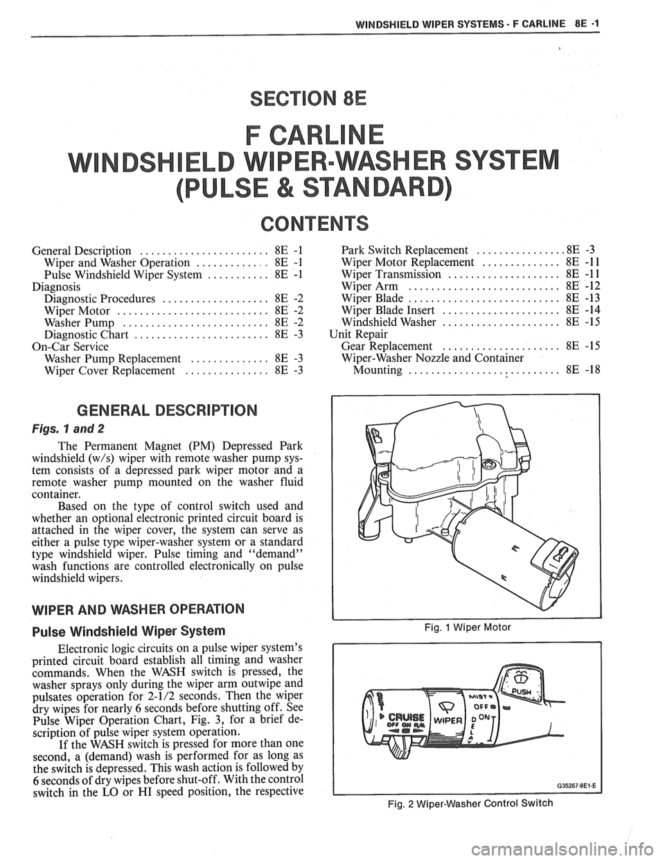
GENERAL DESCRIPTION
Figs. hand 2
The Permanent Magnet (PM) Depressed Park
windshield
(w/s) wiper with remote washer pump sys-
tem consists of a depressed park wiper motor and a
remote washer pump mounted on the washer fluid
container.
Based on the type of control switch used and
whether an optional electronic printed circuit board is
attached in the wiper cover, the system can serve as
either a pulse type wiper-washer system or a standard
type windshield wiper. Pulse timing and "demand"
wash functions are controlled electronically on pulse
windshield wipers.
WIPER AND WSHER OPERAflON
Pulse Windshield Wiper System Fig. 1 Wiper Motor
Electronic logic circuits on a pulse wiper system's
printed circuit board establish all timing and washer
commands. When the WASH switch is pressed, the
washer sprays only during the wiper arm
outwipe and
pulsates operation for 2-1/2 seconds. Then the wiper
dry wipes for nearly
6 seconds before shutting off. See
Pulse Wiper Operation Chart, Fig.
3, for a brief de-
scription of pulse wiper system operation.
If the WASH switch is pressed for more than one
second, a (demand) wash is performed for as long as
the switch is depressed. This wash action is followed by
6 seconds of dry wipes before shut-off. With the control
switch in the
LO or HI speed position, the respective
Fig. 2 Wiper-Washer Control Switch