1988 PONTIAC FIERO lug pattern
[x] Cancel search: lug patternPage 260 of 1825

REAR AXLE 481-7
ON-VEHICLE SERVICE
CARRIER COVER AND GASKET
Remove or Disconnect
1. Having
a container in place remove drain plug
with tool
J-35117,remove cover bolts and pry
cover loose to drain lubricant.
2. Make sure both
gasket sealing surfaces are clean.
Install or Connect
Use cover gasket (do not assemble with
sealant alone).
NOTICE: Apply locktite part No. 573, GM Part
Nos. 1052080, or 1052279 or equivalent to cover
bolts before installing cover. If sealant is not applied
bolts may loosen causing fluid leak and damage to
rear axle assembly.
1. Torque cover bolts in a crosswise pattern to
insure uniform draw on gasket. Torque
26 N.m
(20 1b.ft.).
2. Fill with lubricant to bottom of filler plug hole.
Refer to specifications for correct lubricant usage
and quantity.
AXLE SHAFT
Remove or Disconnect
1. Wheel
and brake components as necessary.
2. The
four nuts holding the brake anchor plate and
outer bearing retainer.
3. Withdraw the axle shaft and wheel bearing assem-
bly using axle shaft remover
J 21579 and slide
hammer
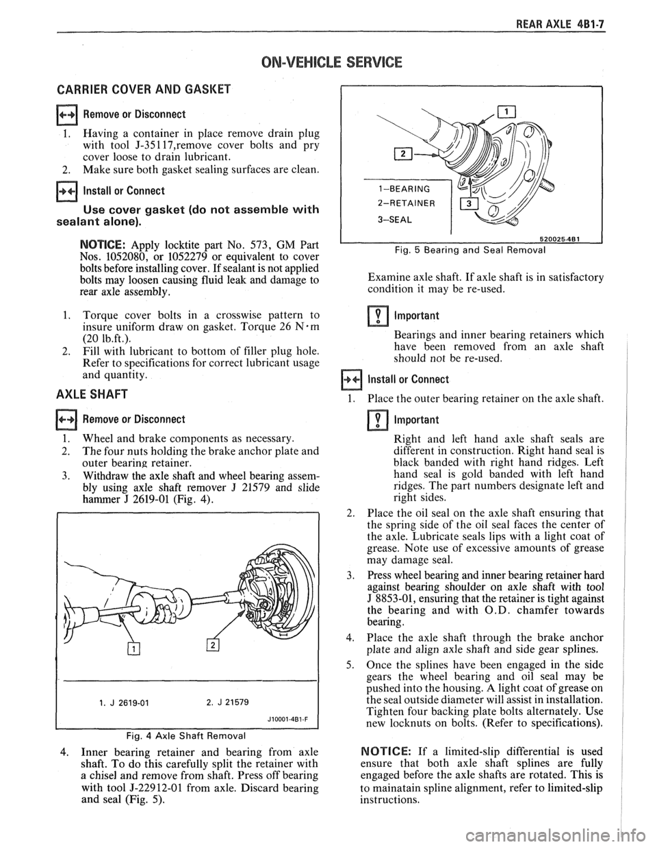
J 2619-01 (Fig. 4).
Fig. 4 Axle Shaft Removal
4. Inner
bearing retainer and bearing from axle
shaft. To do this carefully split the retainer with
a chisel and remove from shaft. Press off bearing
with tool
5-22912-01 from axle. Discard bearing
and seal (Fig. 5).
Fig. 5 Bearing and Seal Removal
Examine axle shaft. If axle shaft is in satisfactory
condition it may be re-used.
Important
Bearings and inner bearing retainers which
have been removed from an axle shaft
should not be re-used.
Install or Connect
1. Place the outer bearing retainer on the axle shaft.
Important
Right and left hand axle shaft seals are
different in construction. Right hand seal is
black banded with right hand ridges. Left
hand seal is gold banded with left hand
ridges. The part numbers designate left and
right sides.
2. Place the oil seal on the axle shaft ensuring that
the spring side of the oil seal faces the center of
the axle. Lubricate seals lips with a light coat of
grease. Note use of excessive amounts of grease
may damage seal.
3. Press wheel bearing and inner bearing retainer hard
against bearing shoulder on axle shaft with tool
J 8853-01, ensuring that the retainer is tight against
the bearing and with
O.D. chamfer towards
bearing.
4. Place the axle shaft through the brake anchor
plate and align axle shaft and side gear splines.
5. Once the splines have been engaged in the side
gears the wheel bearing and oil seal may be
pushed into the housing.
A light coat of grease on
the seal outside diameter will assist in installation.
Tighten four backing plate bolts alternately. Use
new locknuts on bolts. (Refer to specifications).
NOTICE: If a limited-slip differential is used
ensure that both axle shaft splines are fully
engaged before the axle shafts are rotated. This is
to mainatain spline alignment, refer to limited-slip
instructions.
Page 264 of 1825

REAR AXLE 4Bl-I I
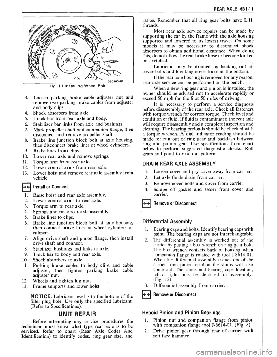
Fig. 11 Installing Wheel Bolt
Loosen parking brake cable adjuster nut and
remove two parking brake cables from adjuster
and body clips.
Shock absorbers from axle.
Track bar from rear axle and body.
Stabilizer bar links from axle and bushings.
Mark propeller shaft and companion flange, then
disconnect and remove propeller shaft.
Brake line junction block bolt at axle housing,
then disconnect brake lines at wheel cylinders.
Brake lines from clips.
Lower rear axle and remove springs.
Torque arm from rear axle.
Lower control arms from rear axle.
Lower hoist and remove rear axle assembly from
vehicle.
Install or Connect
Raise hoist and rear axle assembly.
Lower control arms to rear axle.
Torque arm to rear axle.
Springs and raise rear axle assembly.
Brake lines to clips.
Brake line junction block bolt at axle housing,
then connect brake lines at wheel cylinders or
calipers.
Align drive shaft and pinion flange, then install
drive shaft and connect.
Stabilizer bushings and links to axle.
Track bar to body and rear axle.
Shock absorbers to axle.
Parking brake cables to body clips and cable
adjuster, then tighten parking brake cable
adjuster nut.
Wheels and tighten lug nuts.
Frame supports and lower hoist.
NOTICE: Lubricant level is to the bottom of the
filler plug hole. Use only the specified lubricant.
(Refer to Specifications).
Before attempting any service procedures the
technician must know what type rear axle is to be
serviced. Refer to chart (Rear Axle Codes And
Identification) to identify codes, ring gear size, and ratios.
Remember that all ring gear bolts have
L.H.
threads.
Most rear axle service repairs can be made by
supporting the car by the frame with the axle housing
supported and lowered to its lowest travel. On some
models it may be necessary to disconnect shock
absorbers to obtain additional clearance. When doing
this, do not allow the rear brake hose to become
kinked
or stretched.
Lubricant may be drained by backing out all
cover bolts and breaking cover loose at the bottom.
If the rear axle housing is removed for any reason,
rear axle service can be performed on the bench.
When a new ring gear and pinion is installed, the
owner should be advised not to accelerate rapidly or
exceed 50 mph for the first 50 miles of driving.
It is necessary to perform a service diagnosis
before disassembly of the rear axle. Check all fasteners
with torque wrench for correct torque. Check level and
condition of fluid.
If fluid is contaminated the rear axle
will require disassembly and a complete inspection and
cleaning. The bearing preloads should be checked with
a torque wrench. A dial indicator reading should be
made for run out of ring gear and backlash between
ring and pinion gear. Use specifications from chart
below to perform suggested diagnostic checks. Roll
gears and paint to read out pattern.
DRAIN REAR AXLE ASSEMBLY
1. Loosen cover and pry cover away from carrier.
2. Let axle fluids drain from carrier.
3. Remove cover bolts and cover from carrier.
4. Scrape off gasket and sealer from cover and
carrier.
Remove or Disconnect
Differential Assembly
1. Bearing caps and bolts. Identify bearing caps with
paint. The bearing caps are not interchangeable.
2. The differential assembly is worked out of the
carrier by putting a box wrench on ring gear bolt.
The box wrench contacts back of housing when
companion
tlange is rotated with tool 3-8614-01.
When the differential assembly rotates out of the
carrier from pinion rotation the shims will also
come out. The shims and bearing caps location,
left or right, must be identified for reassembly.
(Fig. 12).
3. Differential assembly from carrier.
Remove or Disconnect
Hypoid Pinion and Pinion Bearings
1. Pinion nut and companion flange from pinion
with companion flange tool 5-8614-01. (Fig. 8).
2. Drive pinion gear through rear of carrier with
soft face hammer.
Page 281 of 1825

4B-8 REAR AXLE
GENERAL lNFORMATlON
A universal joint connects the rear end of the
propeller shaft to a pinion flange, having a splined end
which fits over and drives the
hypoid pinion gear. The
housing is attached to the underbody through a center
bearing support. Inside the housing, an extension shaft
is splined to the drive pinion at the rear end, and to the
companion flange at the other end. Two pre-loaded
tapered roller bearings support the
hypoid pinion gear
in the carrier. The inner race of the rear bearing is a
light press fit on the pinion stem. The inner race of the
front bearing combines a light press fit to a close sliding
fit on the pinion flange end of the pinion stem. The
outer race of each bearing is pressed against a shoulder
recessed in the carrier. Tightening the pinion nut
compresses a collapsible spacer which bears against the
inner race of the front bearing and a shoulder on the
pinion stem. This spacer is used to enable accurate
bearing pre-load adjustment and
maintain a pre-load
on both front and rear pinion bearings. Adjustment of the
fore and aft position of the pinion is obtained by
placing
shims between the head of the drive pinion and
the rear pinion bearing.
The rear axle case is of
one-piece construction and is supported in the carrier
by two tapered roller side bearings. These are
pre-loaded by inserting
shims between the bearings and
the carrier. The rear axle case assembly is positioned
for proper ring gear to pinion backlash by varying the
shin1 thickness from side to side. The ring gear is bolted
to the case. Two side gears have splined bores for
driving the axle shafts. They are positioned to turn in
counterbored cavities in the case. The two rear axle
pinions have
smooth bores and are held in position by
a solid pinion cross shaft, mounted and locked in the
rear axle case. All four gears are in
mesh with each
other and because the pinion gears turn freely
on their
shaft, they act as idler gears when the rear wheels are
turning at different speeds. The pinions and side gears
are backed by steel thrust washers.
LIMITED-SLIP REAR AXLE
The operation of the Limited-Slip differential is
the same as the standard differential, except that there
is additional friction provided by the clutches or cones.
Under ordinary driving and cornering conditions, the
clutches or cones slip, allowing the outside wheel to
turn faster than the inner. Under poor traction
conditions, such as ice, snow, or loose gravel under one
driving wheel, the increased friction provided by the clutches
or cones increases the driving torque available
to the wheel with the better traction. The clutches or
cones are spring loaded to provide the increased
driving torque under extremely low traction
conditions.
Most rear axle service repairs can be made with
the rear axle assembly in the car, by raising the rear end
of the car with the rear axle hanging
on the shock
absorbers.
ON-VEHICLE SERVICE
CARRIER COVER AND GASKET
Remove or Disconnect
1. Having a container in place, remove cover bolts
and pry cover loose to drain lubricant.
2. Make sure both gasket sealing surfaces are clean.
Install or Connect
Use sealant
1052366 or cover gasket
only.
1. Torque cover bolts in a crosswise pattern to
insure uniform draw on gasket. Torque
27 N.m
(20 Ib.fr.).
2. Fill with lubricant to a level within 4.5mm (3116")
or filler plug hole. Refer to specifications for correct
lubricant usage and quantity.
Axle Shaft
a Remove or Disconnect
1. Raise car and remove wheel and brake drum.
2. Clean all dirt from area of carrier.
3. Remove bolts and differential carrier cover and
allow lubricant to drain.
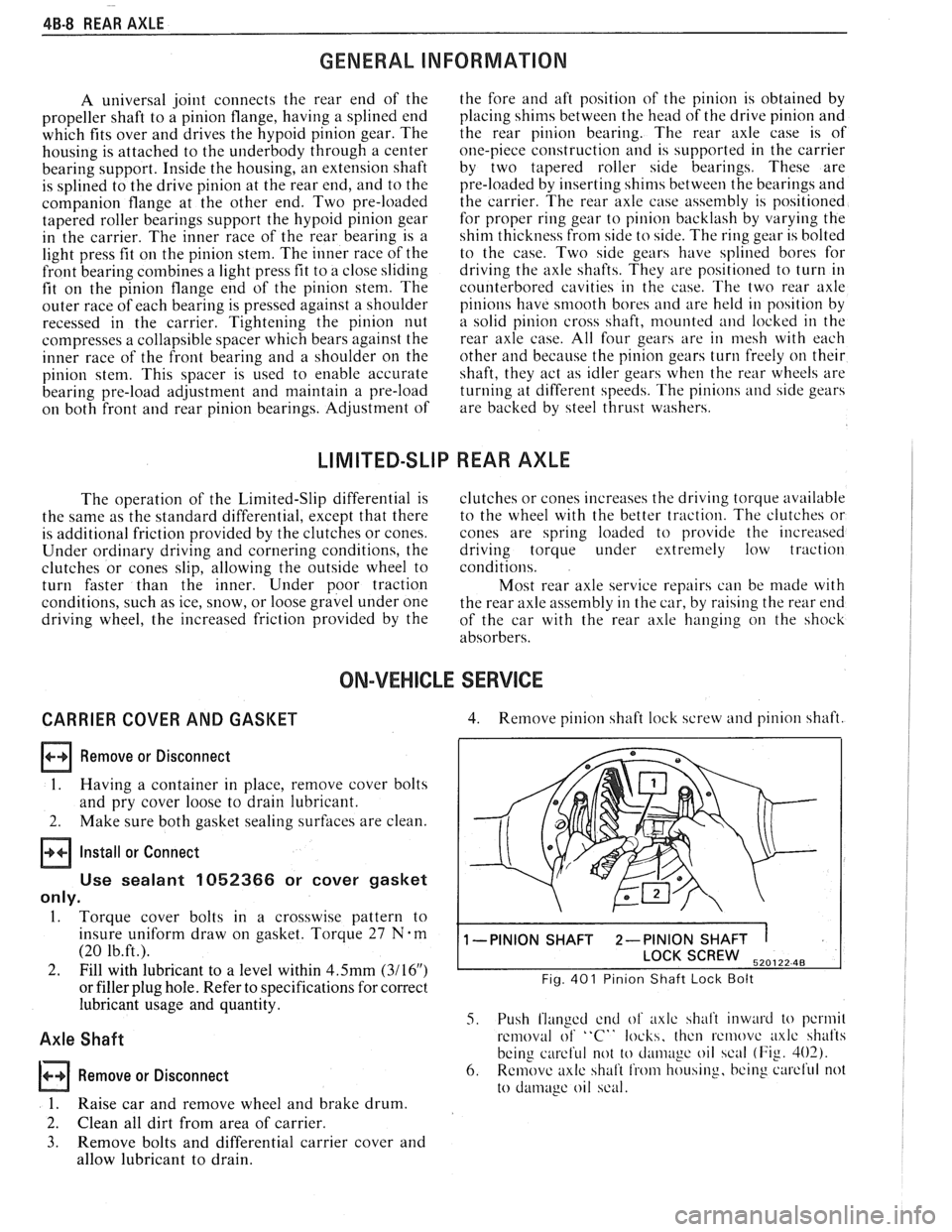
4. Remove pinion shaft lock screw and pinion shaft.
1 -PINION SHAFT 2-PINION SHAFT 1
SCREW 520122 48
Fig. 401 Pinion Shaft Lock Bolt
5. Push flanged end of axlc shalt inward to pcrmil
removal of "C" locks, thcn rcmovc axlc shafts
being
careful not to cl;uii~~gc oil scal (Fig. 402).
6. Remove axlc shaft from housing, bcing curcl'ul not
to
damage oil scal.
Page 1642 of 1825

WINDSHIELD WIPER SYSTEMS F CARLlNE BE -15
ASSEMBLING
ANGLED OPEN
AREA OF CAM.
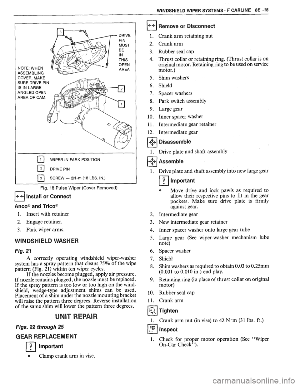
WIPER IN PARK POSITION
SCREW
- 2N.m (18 LBS. IN.)
Fig. 18 Pulse Wiper (Cover Removed)
Install or Connect
Aneo@ and Trico@
Remove or Disconnect
Crank arm retaining nut
Crank arm
Rubber seal cap
Thrust collar or retaining ring. (Thrust collar is on
original motor. Retaining ring to be used on service
motor.)
Shim washers
Shield
Spacer washers
Park switch assembly
Large gear Inner spacer washer
Intermediate gear retainer
Intermediate gear
Disassemble
Drive plate and shaft assembly
Assemble
1. Drive plate and shaft assembly into new large gear
Important
Move drive and lock pawls as required to
allow their respective pins to fit in the gear
pockets. Make sure drive plate is firmly
against gear.
1. Insert with retainer 2. Intermediate gear
2. Engage retainer. 3. New intermediate gear retainer
3. Park wiper arms. 4. Inner spacer washer onto large gear tube
WINDSHIELD WASHER 5. Large gear (See wiper-washer mechanism lube
note)
Fig. 21 6. Spacer washer
A correctly operating windshield wiper-washer
system has a spray pattern that cleans
75% of the wipe
pattern (Fig. 21) within ten wiper cycles.
If the nozzles become plugged, apply air pressure.
If nozzle remains plugged, the nozzle must be replaced.
If the spray pattern is too low or too high on the wind-
shield, wedge-type adjustment shims can be used.
Placement of a shim under the nozzle mounting bracket
will raise the pattern three degrees. Reverse installation
of the same shim will lower the pattern three degrees.
UNIT REPAIR
Figs. 22 through 25
GEAR REPLACEMENT
Important
7. Shield
8. Shim washers as required to obtain 0.03 to 0.25mm
(0.001 to 0.010 in.) end play.
9. Retaining ring (in place of thrust collar on original
motor)
10. Rubber seal cap
11. Crank arm
Tighten
1. Crank arm nut (in vise) to 42 N' m (3 1 Ibs. ft.)
Inspect
1. Check for proper motor operation (See "Wiper
On-Car Check").
Clamp crank arm in vise.