1988 PONTIAC FIERO tire type
[x] Cancel search: tire typePage 2 of 1825
1988
SER
This manual applies to the 1988 Pontiac Firebird Models.
It contains the latest product information available at the
time of publication approval. lnformation pertaining to
the operation of the vehicle is contained in the Owner's
Manual which accompanies each vehicle. The right is
reserved to make changes at any time without notice.
Any references to brand names in this manual is intended
merely as an example of the types of
lubricant% tools,
materials, etc, recommended for use in servicing 1988
Pontiac Models. In all cases, an equivalent may be used.
PONTIAC DIVISION
GENERAL
MOTORS CORPORATION
PONTIAC, MICHIGAN 48053
1987 General Motors Corp. All Rights Reserved.
No part of this publication may be reproduced, stored in any
retrieval system or transmitted in any form or by any means,
including but not limited to electronic, mechanical,
photocopying, recording or otherwise, without the prior written
permission of General Motors Corp. This includes all text,
illustrations, tables and charts.
S-881 OF 9-87 Printed in Canada
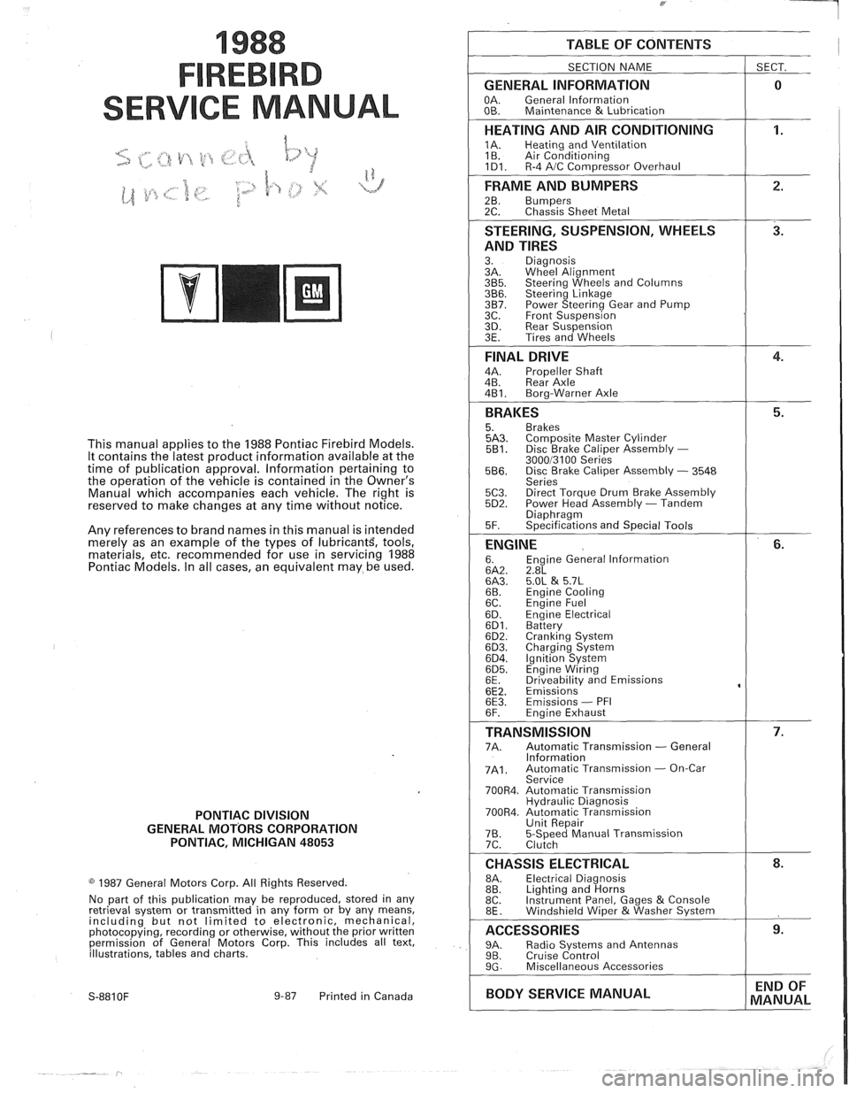
TABLE OF CONTENTS
SECTION NAME
GENERAL INFORMATION
OA. General lnformation
OB. Maintenance & Lubrication
1 SECT.
HEATING AND AIR CONDITIONING
1A. Heating and Ventilation
1 B. Air Conditioning
1D1. R-4 AIC Com~ressor Overhaul
FRAME AND BUMPERS
2B. Bumpers 2C. Chassis Sheet Metal
STEERING, SUSPENSION, WHEELS
AND TIRES
3. Diagnosis
3A. Wheel Alignment
3B5. Steering Wheels and Columns 3B6. Steering Linkage 3B7. Power Steering Gear and Pump
3C. Front Suspension
3D. Rear Suspension
3E. Tires and Wheels
FINAL DRIVE
4A. Propeller Shaft
4B. Rear Axle
4B1. Bora-Warner Axle
BRAKES 5. Brakes 5A3. Comoosite Master Cvlinder 5B1. Disc r rake Caliper ~ssembly - 300013100 Series 5B6. Disc Brake Caliper Assembly - 3548
Series
5C3. Direct Torque Drum Brake Assembly 5D2. Power Head Assembly - Tandem Diaohraam 5F. ~~ecifications and Special Tools
ENGINE 6. Engine General lnformation 6A2. 2.8L 6A3. 5.OL & 5.7L 6B. Engine Cooling
6C. En~ine Fuel
6D. ~ngine Electrical 6D1. Battery 6D2. Cranking System 6D3. Charging System 6D4. Ignition System 6D5. Engine Wiring
6E. Driveabilitv and Emissions
6E2. ~missions' 6E3. Emissions - PFI
6F. Engine Exhaust
TRANSMISSION 7A. Automatic Transmission - General
lnformation
7A1. Automatic Transmission - On-Car
Service
700R4. Automatic Transmission Hydraulic Diagnosis
700R4. Automatic Transmission Unit Repair
76. 5-Speed Manual Transmission
7C. Clutch
CHASSIS ELECTRICAL 8A. Electrical Diagnosis
8B. Lighting and Horns
8C. Instrument
Panel, Gages
& Console
8E. Windshield Wiper &Washer System
ACCESSORIES 9A. Radio Systems and Antennas 9B. Cruise Control 9G. Miscellaneous Accessories
I BODY SERVICE MANUAL END
OF
MANUAL
Page 46 of 1825
AIR CONDITIONING 1 B-3
A low-side pressure Schrader valve service fit-
ting is located near the top of the accumulator. A
similar Schrader fitting may be provided for mounting
the pressure cycling switch. It is not necessary to dis-
charge the system to replace the switch. The accumu-
lator is serviced only as a replacement assembly.
Heater Core
The heater core heats the air before it enters the
car. Engine coolant is circulated through the core to
heat the outside air passing over the fins of the core.
The core is functional at all times (no water valve) and
may be used to temper conditioned air in
A/C mode,
as well as heat or vent mode.
SYSTEM COMPONENTS --- CON"FOL
Controller
The operation of the A/C system is controlled by
the switches and the lever on the control head. The
compressor clutch and blower are connected electri-
cally to the control head by a wiring harness. The
blower circuit is open in the off mode and air flow is
provided by the four blower speeds available in the
remaining modes. Cooled and dehumidified air is
available in the max, normal, bi-level and defrost
modes.
Temperature is controlled by the position of the
temperature lever on the control head. A cable con-
nects this lever to the temperature door which controls
air flow through the heater core. As the temperature
lever is moved through its range of travel, a sliding
clip on the cable at the temperature valve connection
should assume a position assuring that the temperature
door will seat in both extreme positions. Temperature
door position is independent of mode selection. The
temperature cable attaches to the right side of the air
conditioning module. The temperature door on some
models is controlled electrically, thereby eliminating
the need for the temperature cable.
The electric engine cooling fan on some cars is
not part of the
A/C system; however, the fan is
operational any time the
A/C control is in Max.,
Norm, or Bi-Level modes. Some models provide for
engine cooling fan operation when the controller is in
the defrost mode. This added feature is part of the
A/C
controller function and is aimed at preventing exces-
sive compressor head temperatures. It also allows the
A/C system to function more efficiently. On some
models during road speed (above
35 mph) conditions
when air flow through the condenser coil is adequate
for efficient cooling, the engine cooling fan will be
turned off. The operation of the cooling fan is con-
trolled by the ECM through the cooling fan relay.
Complete wiring diagrams and diagnosis for the
AIC Electrical System are in Section 8A. Section 8A
also contains additional diagnostic information
regarding air flows and vacuum logic.
Vacuum Lines
Vacuum lines are molded to a connector which
is attached to a vacuum control switch on the control
head assembly.
In case of leakage or hose collapse, it will not be
necessary to replace the entire harness assembly.
Replacement can be made by cutting the hose and
inserting a plastic connector. If an entire hose must be
replaced, cut all hoses off at the connector and then
attach hoses directly to the control head vacuum
switch. (NOTE: The Fiero uses an electric motor to
control mode selection. Therefore, it will not have a
vacuum harness.
)
Vacuum Tank
During heavy acceleration, the vacuum supply
from the carburetor drops. A check valve in the vac-
uum tank maintains vacuum so that, under load condi-
tions, vacuum will be available for continuous use.
REWVS AND SWITCHES
High-Pressure Compresssr Gut-OFF Switch
The high-side, high-pressure cut-off switch in
the rear head of the compressor is a protective device
intended to prevent excessive compressor head pres-
sures and reduce the chance of refrigerant escape
through a safety relief valve. Normally closed, this
switch will open the circuit at a high-side pressure of
approximately 2700
kPa (430 psi 9 20 psi) and
reclose the circuit at approximately 1379 kPa (200 psi
9 50 psi).
Lsw-Pressure Cut-On Switch
Compressor protection is provided on some cars
by a low-pressure cut-off switch which will open in
the event of a low-charge condition. This switch can
be located in the liquid line or in the rear head of the
compressor. This switch will also keep the compres-
sor from running during cold weather.
Pressure eyesing Switch
The refrigeration cycle (on and off operation of
the compressor) is controlled by a switch which
senses the low-side pressure as an indicator of evapo-
rator temperature. The pressure cycling switch is the
freeze protection device in the system and senses
refrigerant pressure on the suction side of the system.
This switch is located on a standard Schrader-type
valve low-side fitting. This switch also provides com-
pressor cut-off during cold weather.
Additional compressor protection results from
the operating characteristics of the low-side pressure
cycling system. If a massive discharge occurs or the
orifice tube becomes plugged, low-side pressures
could be insufficient to close the contacts of the pres-
sure switch. In the event of a low charge, insufficient
cooling accompanied by rapid compressor clutch
cycling will be noticed at high air temperatures.
Page 47 of 1825

18-4 AIR CONDITIONING
If replacement of the pressure cycling switch is
necessary, it is important to note that this may be done
without removing the refrigerant charge.
A Schrader-
type valve is located in the pressure switch fitting.
During replacement of the pressure switch, a new
oiled O-ring must be installed and the switch assem-
bled to the specified torque of
6- 13 N*m (5- 10 lb. ft.).
Power Steering Gut-OH, or Anticipate
Switch
Engine idle quality on some cars is maintained
by cutting off the compressor (switch normally
closed) when high power steering loads are imposed.
On other cars the switch (normally open) provides a
signal to the ECM to allow engine control systems to
compensate for high-power steering loads.
Wide-Open Tkroale (WOT) Compressor
Cut-Out
Switch
A switch located on the throttle corltrols of some
carburetor equipped cars opens the circuit to the com-
pressor clutch during full throttle acceleration. The
switch activates a relay that controls the compressor
clutch. During full throttle acceleration
on cars
equipped with TBI or
Em, the TPS sends a signal to
the ECM, thereby controlling the compressor clutch.
Air Conditioning Time Delay Relay
This relay on some cars controls the current to
the entire air conditioning system and provides a short
delay of air conditioning operation upon start-up.
Constant Run Relay
Engine idle quality on some cars is maintained
by a "constant run" system (constant run relay) that
eliminates compressor cycling during engine idle for a
predetermined time after the vehicle has come to rest
from road speed.
If the idle period continues for an
extended time, the
A/C system may return to a con-
ventional C.C.O.T. mode for a short time to prevent
system freeze-up. The
A/C control relay and constant
run relays are both controlled by the Electronic Con-
trol Module (ECM) which determines operating con-
ditions by evaluating input from the distributor
(engine speed), vehicle speed sensor, air sensor and
A/C compressor "on" signal.
5-PRESSURE CYCLING 8-EXPANSION TUBE
SWITCH (ORIFICE)
6-DESSICANT BAG O-LIQUID LINE
7-OIL BLEED HOLE
10-PRESSURE RELIEF
VALVE
@ ee LOW PRESSURE LIQUID HIGH PRESSURE LIQUID LOW PRESURE VAPOR HIGH PRESSURE VAPOR
Figure 2 A/C System - Typical
Page 102 of 1825
BUMPERS 28-1
SECTION 2B
BUMPERS
NOTICE: These fasteners are important attaching parts in that they could affect the performance of vital parts and
systems,
andlor could result in major repair expense. They must be replaced with one of the same part number or with an
equivalent
part if replacement becomes necessary. Do not use a replacement part of lesser quality or substitute design.
Torque values must be used as specified during reassembly to assure proper retention of all parts. There is to be no
welding as it may result in extensive damage and weakening of the metal.
NOTICE: The anti-theft label on some major sheet metal, engines, and transmissions must be masked prior to
painting, rustproofing, undercoating, etc. The mask MUST be removed following the above operations. Failure to keep
the label clean and readable may result in liability for violation of Federal Vehicle Theft Prevention Standard, and subject
the vehicle owner to possible suspicion that the part was stolen.
CONTENTS
General Description ................................ 2B-1 On-Vehicle Service ..................................... 2B-4
........................................... ..................... Service Procedures .. ........... 2B- 1 Specifications 2B-5
GENERAL DESCRIPWIBN
The bumpers on all Pontiac automobiles are remover.
Install new tape (double-coated neoprene
designed so that the vehicle can withstand a collision foam type)
to the back side of the rub strip.
into a fixed barrier at
5 mph. After absorbing the
energy of a collision, the bumpers restore themselves After
rub strip is installed, roll along entire
to their original position. surface with a roller
in order to insure a good bond.
The front and rear bumper fascias are made of
urethane. Urethane will withstand minor impact and
return to its original shape. Some front bumper fascias
are integral with the front end panel.
Some models use both steel and aluminum
bumper reinforcements. Usage is based on
EPA weight
class requirements.
BUMPER FASCIA RUB STRIPS
Some front and rear fascia rub strips are made of
a shiny plastic material. If a rub strip of this type loses
its lustre, the original shine can be restored by using
GM Plastic Cleaner or its equivalent. Follow directions
on the label.
SERVICE PROCEDURES
RUB STRIPS
Remove and Replace
Some plastic rub strips have an adhesive tape
backing (similar to a body side molding) and some have
studs or retaining tabs. In order to properly remove the
adhesive tape and avoid paint damage to the fascia, use
either a release agent or a heat lamp to soften the bond
of the adhesive tape to the fascia. In some cases, it will
be necessary to replace the rub strip with a new rub
strip instead of reusing the old one.
If the old rub strip is salvagable, remove all tape
from the back side of the rub strip as previously
described. Wipe strip clean with a wax and adhesive
FRONT BUMPER FASCIA (FRONT END PANEL)
Removal
Place a jack stand under fascia assembly before
removing bolts to prevent it from dropping down when
fascia attaching bolts are removed. Fascia will pivot on
the opposite end when one end is disconnected. Do not
rotate energy absorber any more than necessary to
align mounting holes.
1. Remove fascia attaching bolts and fascia to
fender attaching screws on right and left side, and
remove fascia and spacers.
2. If energy absorber is to be replaced, remove the
bolts and nuts from the front of the unit and the
nut from the stud at the rear.
Installation
1. Install energy absorber if removed.
2. Support fascia during installation to prevent
rotation of energy absorbers.
3. Install spacers and bolts at fascia to energy
absorber brackets.
4. Install fascia to fender attaching screws.
5. Check for proper clearance.
6. If adjustment is required to align fascia, loosen
energy absorber mounting bolts and position as
required (holes are slotted). Adjustment side to
side can be made by loosening fascia bracket
bolts. Torque all bolts and nuts. (See
Specifications.)
Page 111 of 1825
2C-4 CHASSIS SHEET METAL
3. Clean area to be repaired.
4. Mix and apply the repair material by using a
putty knife or rubber squeegee.
5. Work the material into the repair and build up
the desired contour. For deep filling, and on
vertical surfaces, several layers may be
required.
6. Feather-sand damaged area with No. 200 sand-
paper and finish-sand with No. 320 sandpaper.
7. Prepare repaired area for refinishing. Refinish
with acrylic lacquer as described below.
1. THOROUGHLY CLEAN the entire surface
area, using Naphtha or equivalent solvent, to
insure a surface free of contamination.
2. To promote paint adhesion, a light scuff-sand-
ing of the surface with
#400-grit sandpaper is
recommended.
3. Repeat cleaning of the surface.
4. Color coat with acrylic lacquer for proper color
match.
5. Allow to dry thoroughly, rub out and polish.
PAINT REFINISHING PROCEDURES FOR
URETHANE, P.V.C. AND T.P.R. SURFACES
Urethane material will withstand minor impact
and the resultant damage, such as occurs in parking
lots, by recovering its original shape. Its Endura paint
film responds to impact in a similar manner without
cracking or splitting. If, however, an area of damage
in the Urethane bumper or panel does not recover its
shape, or the surface is punctured, gouged or torn, a
repair system has been developed to restore the origi-
nal shape and appearance of the urethane-base
material.
CALSVON: There are a number of paint
systems available For service use; how-
ever,
many require additives containing
isocyanates.
It is essential that all rec-
ommendations and warnings listed on
the container label for
materials
seleded be followed.
CAUTION: If the paint system selected
specifies an additive containing
isocya-
nates, it is mandatory that adequate
respiratory protection be worn. An
example of such protection
is an air line
respirator with a
full hood or half mask.
If not
avaiable, use a vaporlpaHiculate
respirator that the respirator supplier
recommends as
efFective for isocyanate
vapors and mists (unless local
regula-
tions prevail).
Such protection should be worn during the
entire painting process. Persons with respiratory
problems, or those
allergic to isocyanates must not
be exposed to isocyanate vapors or spray mist.
REPAIRING & REFINISHING URETHANE
BUMPERS AND FRONT END PANELS
Required Materials:
1. 3M No. 8101 Structural Adhesive, or
equivalent.
2. Color Coat - Dexlar (DuPont) Flexible Finish
Enamel Color Coat, or Ditzler Elastomeric
Enamel Color Coat or equivalent.
3. Additive
- DuPont 792s Centari Hardener,
or
Ditzler
DXR-80 Delthane Additive or
equivalent.
4. Thinner
- DuPont 3608s Acrylic
Lacquer
Thinner, or Ditzler Delstar DTR 601 Acrylic
Enamel Reducer or equivalent.
NOTICE: Use the same brand name materials for
the color coat, additive, and thinner.
5. A wax and adhesive cleaner.
Equipment Needed:
1. Wooden spatula (enclosed in repair package).
2. Heat lamp.
3. 36 grit 180-A, 240-A, and 320-A grit disc
sandpaper.
4. Random orbital-type sander.
5. Body repair tape.
6. Suction spray gun (same nozzle and air cap
combination as used for acrylic).
Repair Procedure
There are three types of repairable damage on
urethane material. They are a puncture, a gouge and a
tear.
Following is the basic repair procedure for
repairing these types of damages.
1. Clean the damaged area with 3M #8984 Gen-
eral Purpose Adhesive Cleaner or equivalent. If
the damage is through the thickness of the part,
clean both sides.
Grind away damaged material with a
36 grit
disc. Feather edge the paint around the damage
using a
1808 grit disc.
2. If the part has a puncture or tear, file or rout out
the area where joint line will be. Bevel the edge
of the part with the open edge towards the side
to be filled (fill from the side with easiest
access). Clean the repair area with a clean dry
rag.
3. Apply 3M #6935 Auto Body Repair Tape, or
equivalent, to the underside of the repair area to
backup the repair material.
NOTICE: Before going to the next step, be sure
all of the paint (both topcoat and primer) has been
removed from the area where the structural adhe-
sive is to be applied.
Page 112 of 1825
CHASSIS SWEET MEWL 2C-5
4. Mix 3M #05900 Structural Adhesive, or equiv-
alent, according to instructions on package. For
best results, use a 2-step application. First, mix
only enough for a thin coat.
Mix adhesive thoroughly with mixing stick
enclosed in package, or a putty knife. HINT: If
you use the mixing stick, bevel the edge to form
a straight, rather than a rounded surface.
5. Apply adhesive over entire area with a rubber
squeegee. Step A: Apply a light coat over entire
area and allow to dry. Step
B: Mix and apply the
contour. Spread from edges of repair towards
center, filling all low areas.
6. Hand level with surrounding area using a 240-A
grit disc. Check for voids and low areas. If nec-
essary mix up more adhesive and apply to low
areas.
Allow each coat of adhesive to dry before apply-
ing subsequent coats. Drying can be quickened
by application of low heat (for example, a low
power heat lamp). DO NOT OVERHEAT.
After final coat, sand using a 320-A grit disc.
7. Scuff-sand entire panel with a 320 grit disc by
hand or with a random orbital type sander. Wipe
entire area to be painted with a clean dry cloth
and/or tack cloth per paint manufacturer's
instructions.
8. Paint panel using Inmont R-M Alpha-Cryl, or
with R-M 891 Urethane Catalyst Flex Agent, or
the Ditzler Elastomeric Enamel Flexible Paint System (DE type), or equivalent urethane paint
systems. Follow label directions.
Coloring Procedure:
1. THOROUGHLY CLEAN the entire surface
area with
3919s Prepsol (DuPont) or equivalent
solvent to insure a surface
free of
contamination.
2. To promote paint adhesion and insure a smooth
surface, a light scuff-sanding with #400-grit
sandpaper (wet or dry) is recommended.
3. Repeat cleaning of the surface.
4. Mask off areas of car not to be painted using
masking tape and paper.
5. Thoroughly mix the color coat, additive and
thinner as suggested on the label directions.
NOTICE: Mix only that which is needed, noting
that pot life is 2-3 hours.
6. Using 35 lbs. of pressure at the gun, spray panel
with
2 or 3 coats (depending on the need) allow-
ing 2-3 minutes flash time between each coat.
Use a final mist coat for metallics.
7. Allow paint to cure 2-4 hours before handling.
8. COMPOUNDING reduces the gloss. For this
reason rubbing compound should be used
only
if a reduction of gloss is desired.
PAINT COLOR MATCHING
If a color coat mismatch between the original
color and the repair material is encountered during
paint repair, a closer color match can be accomplished
by following these recommendations. Assistance may
also be solicited from the manufacturing repre-
sentative of the paint supplier.
1. Stir the paint thoroughly both before and after
thinning.
2. If the repair is too light and metallic looking
after spraying a couple of coats, it can be dark-
ened by spraying
several wet coats. One or more
of the following adjustments can be made to
produce a wetter spray:
a. Open fluid feed valve more.
b. Reduce size of pattern.
c. Decrease gun distance.
d. Slow down stroke.
e. Allow less flash time between coats.
f.
Case should be taken to prevent flooding
and mottling.
3. If
the repair is too dark, spray several coats that
are lighter and more metallic looking. Reverse
the above adjustments using one or more of the
following:
a. Close fluid valve slightly.
b. Increase the size
of the pattern.
c. Increase gun distance.
d. Speed up stroke.
e. Increase flash time between
coats.
f. Care should be
taken, as dry spray
increases orange peel.
4. When matching a difficult color that has a line
of definition, such as a panel or spot repair on an
edge, blend the fourth and fifth coats into the
adjacent panel.
5. Experienced painters generally have the ability
to tint colors for incorrect color hue. Tinting
guides are available from the various paint man-
ufacturers for those who have the base tinting
colors and the ability to tint colors to match.
REMEMBER
- The true color of metallics
will not come through until the finish has been com-
pounded and buffed.
Painting Primed Service Replacement
Urethane Panels
Follow Steps 1 thru 8 under "Coloring
Procedure.
"
Page 117 of 1825
2C-10 CHASSIS SHEET METAL
ROCKER PANEL AIR DEFLECTOR
Remove or Disconnect
1. Five top screws (#I).
2. Hoist car.
3. Seven bolts holding rocker panel rubber
air
deflector
(#2) and remove.
4. Seven screws holding rocker deflector to bottom
of rocker panel
(#3).
5. Two screws holding rear rocker deflector to rear
wheel opening
(#4).
6. Five
push type fasteners at the lower rear of the
wheel well splash shield, lift shield to gain
access to the two forward nuts.
7. Two nuts (#5) from rocker deflector front to
fender.
8. Rocker deflector.
9. Nine screws holding rocker panel deflector
support.
10. Support.
Install or Connect
To install, reverse removal procedure.
REAR BUMPER FASCIA EXTENSION
Remove or Disconnect
1. Hoist car,
2. Drill out
eight fascia extension to fascia rivets
(#I) (four each side). Four
bolts from fascia extension to lower quar-
ter panel
(#2).
Five (each side) push clips from fascia to sup-
port
(443).
Four screws from rear fascia extension to fender
(#4).
Lower car.
Right side trunk trim and spare tire.
Rear trim panel.
Left trim panel.
Right and left side fascia and fascia extension
nuts (six each side)
(#5).
Right and left tail lamp wing nuts and remove
housing.
Seven fascia push nuts and disconnect electrical
connector for license plate
(#6).
Rear bumper fascia from car.
Twelve (six each side) fascia extension to fascia
retaining nuts and remove fascia extension
(#7).
Install or Connect
To install, reverse removal procedure.
Page 135 of 1825

3-10 STEERING, SUSPENSION, TIRES AND WHEELS DIAGNOSIS
Reminder Keeps Operating With Key In Lock
Cylinder, Driver's Door Open Or Closed; Ceases
When Key Is Removed
Inspect
s Door jamb switch on driver's side misadjusted or
inoperative.
e Wire from signal switch to door jamb switch
shorted.
A. This condition indicates the lock cylinder or
the reminder switch is at fault. To verify,
check for continuity at the
"E" and "F"
male column connector contacts, with the
key removed from the lock cylinder. If
continuity exists, the fault is in the column.
B. Insert the key into the lock, then turn the
lock toward the "Start" position. If the
reminder stops when the key is in the
"Run" position or when it is turned past
"Run" toward "Start," the problem is a
sticky lock cylinder actuator.
COLUMN-MOUNTED DIMMER SWITCH
No "Low" or "High" Beam
Inspect
e Loose connector at dimmer switch
e Improper adjustment
e Internally damaged or worn switch. Check the
continuity on the switch at the It. green and at the
tan switch terminals by pushing in the plunger all
the way.
A click should be heard. If there is no
continuity, replace the dimmer switch. If there is
continuity, refer
to'section 8A for electricaldiag-
nosis.
PIVOT AND SWITCH ASSEMBLY
Switch Inoperative: No "Low," "High" and/or
"Wash"
e Loose body-to-switch connector
a Broken or damaged switch
Internally damaged or worn switch. Connect a
new switch without removing the old one. If the
system functions, replace the switch. If the
system doesn't function, refer to Section
8A for
electrical diagnosis.
STEERING GEAR AND PUMP LEAKS
General Procedure
Inspect
s Overfilled reservoir
s Fluid aeration and overflow
e , Hose connections
Verify exact point of leakage Example:
Torsion bar, stub shaft and
adjuster seals are close together; the exact
spot where the system is leaking may not be
clear.
Example: The point from which the fluid is
dripping is not necessarily the point where
the system is leaking; fluid overflowing from
the reservoir, for instance.
e When service is required:
A. Clean leakage area upon disassembly.
B. Replace leaking seal.
C. Check component sealing surfaces for
damage.
D. Reset bolt torque to specifications, where
required.
Some complaints about the power steering system
may be reported as:
A. Fluid leakage on garage floor
B. Fluid leaks visible on steering gear or pump
C. Growling noise, especially when parking or
when engine is cold
D. Loss of power steering when parking
E. Heavy steering effort
When troubleshooting these kinds of complaints,
check for an external leak in the power steering system.
For further diagnosis of leaks, refer to External
Leakage Check in this section.
External Leakage Check
Fig. 12
The purpose of this procedure is to pinpoint the
location of the leak.
In some cases, the leak can easily be located. But,
seepage-type leaks may be more difficult to isolate. To
locate seepage leaks, use the following method.
1. With the engine off, wipe dry the complete power
steering system.
2. Check the fluid level in the pump's reservoir. Add
fluid if necessary.
3. Start the engine, then turn the steering wheel
from stop to stop several times. Do not hold it at
a stop for any length of time, as this can damage
the power steering pump. It is easier if someone
else operates the steering wheel while you search
for the seepage.
4. Find the exact area of the leak and repair leak.
SEAL REPLACEMENT
RECOMMENDATIONS
Lip seals, which seal rotating shafts, require
special treatment. This type of seal is used on the
steering gear and on the drive shaft of the pump. When
there is a leak in one of these areas, always replace the
seal(s), after inspecting and thoroughly cleaning the
sealing surfaces. Replace the shaft only if very severe
pitting is found. If the corrosion in the lip seal contact
zone is slight, clean the surface of the shaft with crocus
cloth. Replace the shaft only if the leakage cannot be
stopped by first smoothing with crocus cloth.