1988 PONTIAC FIERO tire type
[x] Cancel search: tire typePage 1687 of 1825
1H-6 GENERAL INFOWMATION - F STYLE
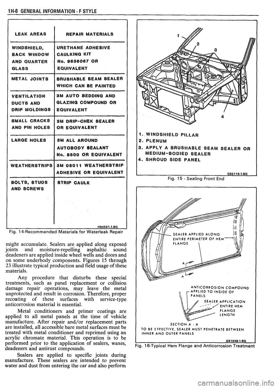
LEAK AREAS I REPAIR MATERIALS
DUCTS AND OLAZlNQ COMPOUND OR
AUTOBODY BEALANT
ADHESIVE OR EQUIVALENT
Fig. 14-Recommended Materials for Waterleak Repair
might accumulate. Sealers are applied along exposed
joints and moisture-repelling asphaltic sound
deadeners are applied inside wheel wells and doors and
on some underbody components. Figures
15 through
23 illustrate typical production and field usage of these
materials.
Any procedure that disturbs these special
treatments, such as panel replacement or collision
damage repair operations, may leave the metal
unprotected and result in corrosion. Therefore, proper
recoating of these surfaces with service-type
anticorrosion material is essential.
Metal conditioners and primer coatings are
applied to all metal panels at the time of vehicle
manufacture. After repair and/or replacement parts
are installed, all accessible bare metal surfaces must be
treated with metal conditioner and
reprimed using an
acrylic chromate material. This operation is to be
performed prior to the application of sealers, waxes,
deadeners and antirust compounds.
1. WINDSHIELD PILLAR
2. PLENUM
3. APPLY A BRUSHABLE SEAM SEALER OR
MEDIUM-BODIED SEALER
4. SHROUD SIDE PANEL
Fig. 15 - Sealing Front End
SEALER APPLIED
ENTIRE PERIMETER OF
FLANGE
ANTICORROSION COMPOUND
APPLIED TO INSIDE OF
SEALER APPLICATION
SECTION A
- A
TO BE EFFECTIVE, SEALER MUST PENETRATE BETWEEN
INNER AND OUTER PANELS
Fig. 16-Typical Hem Flange and Anticorrosion Treatment
Sealers are applied to specific joints during
manufacture. These sealers are intended to prevent
water and dust from entering the car and also perform
Page 1689 of 1825
1 ti-8 GENERAL INFORMATION - F STYLE
5. Apply deadeners (as indicated by original
application pattern).
6. Apply anticorrosion compounds.
9. Apply underbody rustproofing material.
Cleaning of interior and underbody panel
surfaces is necessary when original galvanized or other
anticorrosion materials have been burned off during
welding or heating operations. Removal of the residue
left from burning will require additional care in such
areas as interior surfaces of box-type construction and
when configurations of the metal panels limit access to
interior surfaces. One or more of the following methods
will remove the residue.
CAUTION: Standard shop practices,
particularly eye protection, should be
followed during these operations to
avoid personal injury.
Where access is possible, scraping can be used. If
a standard putty knife or scraper will not fit into
the affected area, consider fabricating a small,
flexible scraper from a narrow piece of sheet
metal.
e A jet of compressed air will remove most residue
and could be most effective in limited-access
areas. Eye protection is absolutely necessary in an
operation of this type.
e Sandblasting is most effective and should be used
when the equipment is available and access to the
area is good. Sandblasting is an excellent method
for cleanup and preparation of open joints,
underbody components and hem flange areas.
e Wire brushing (power and by hand).
e When access is good, sandpaper and steel wool
can be used.
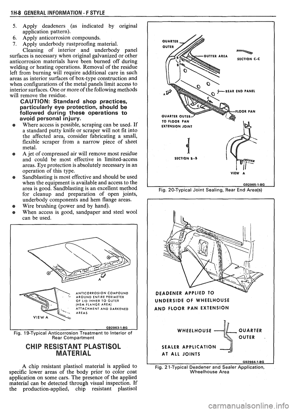
ANTICORROSION COMPOUND AROUND ENTIRE PERIMETER OF LID INNER TO OUTER (HEM FLANGE AREA) ' ATTACHMENT AND DARKENED AREAS
Fig. IS-Typical Anticorrosion Treatment to Interior of Rear Compartment
CHIP RESISTANT PLASTISOL
MATERIAL
A chip resistant plastisol material is applied to
specific lower areas of the body prior to color coat
application on some cars. The presence of the applied
material can be detected through visual inspection. If
the production-applied, chip resistant plastisol
*REAR END PANEL A"'
10 FLOOR PAN
Fig. 20-Typical Joint Sealing, Rear End Area(s)
UNDERSIDE OF WHEELHOUSE
AND FLOOR PAN EXTENSION
WHEELHOUSE QUARTER
OUTER
.
SEALER APPLICATION
AT ALL JOINTS
692964-1.80
Fig. 2 1-Typical Deadener and Sealer Application,
Wheelhouse Area
Page 1691 of 1825
1 W-10 GENERAL INFORMATION - F STYLE
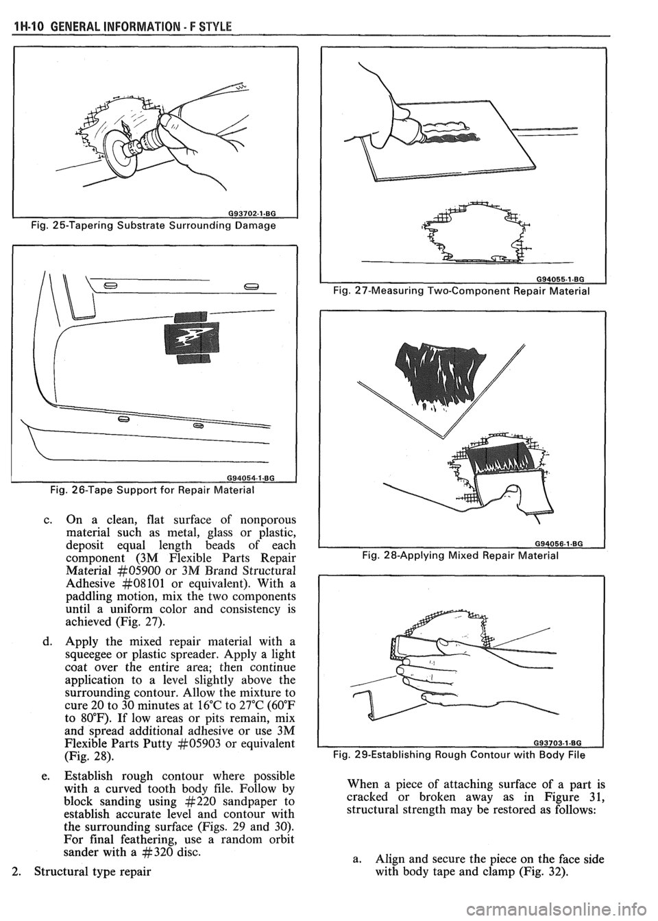
Fig. 25-Tapering Substrate Surrounding Damage
Fig. 26-Tape Support for Repair Material
c. On a clean, flat surface of nonporous
material such as metal, glass or plastic,
deposit equal length beads of each
component (3M Flexible Parts Repair
Material
#05900 or 3M Brand Structural
Adhesive
#08101 or equivalent). With a
paddling motion, mix the two components
until a uniform color and consistency is
achieved (Fig. 27).
d. Apply the mixed repair material with a
squeegee or plastic spreader. Apply a light
coat over the entire area; then continue
application to a level slightly above the
surrounding contour. Allow the mixture to
cure 20 to 30 minutes at 16°C to 27°C (60°F
to 80°F). If low areas or pits remain, mix
and spread additional adhesive or use 3M
Flexible Parts Putty
#05903 or equivalent
(Fig. 28).
e. Establish rough contour where possible
with a curved tooth body file. Follow by
block sanding using
#220 sandpaper to
establish accurate level and contour with
the surrounding surface (Figs. 29 and 30).
For final feathering, use a random orbit
sander with a
#320 disc.
Fig. 27-Measuring Two-Component Repair Material
Fig. 29-Establishing Rough Contour with
Body File
When a piece of attaching surface of a part is
cracked or broken away as in Figure 31,
structural strength may be restored as follows:
a. Align and secure the piece on the face side
with body tape and clamp (Fig.
32). 2. Structural type repair
Page 1694 of 1825
GENERAL INFORMATION 5 F STYLE 1H-13
4. Prime entire area with 3M Polyolefin Adhesion
Promoter Part
kt05907 or equivalent before
filling with 3M Flexible Parts Repair Material
kt05900 or equivalent.
5. Shape repair material with curved body tooth file.
Then block sand with
#220 grit disc and final
featheredge with
#320 grit disc.
6. If low areas or pits remain, first reapply 3M
Polyolefin Adhesion Promoter or equivalent,
then mix and spread additional repair material.
Painting Flexible Parts - E/P or TPO
When painting flexible plastic exterior parts
identified as E/P or TPO, a polypropylene primer
must be used. Follow manufacturer's label
instructions.
METAL REPLACEMENWARTS
FINISHING
Metal service replacement parts (or assemblies)
are painted with a high-bake factory primer. For
proper adhesion of color coats in service, the following
refinish steps are necessary.
1. Clean part with a wax and grease-removing
solvent such as Prep-sol, Pre-Kleano,
Sher-Will-Clean, Acryli-Clean or equivalent.
2. Scuff-sand panel lightly with wet or dry no. 400
sandpaper and water. Avoid cut-throughs.
Reclean part. Apply sealer to entire part.
3. If factory primer coat was cut through, apply
metal conditioner to exposed bare metal. Follow
label directions.
4. Apply primer-surfacer to entire part; allow to dry
thoroughly before sanding. Follow label
directions for drying time.
5. Sand primer-surfacer using wet or dry no. 400
sandpaper and water. Do not sand sealer.
6. Reclean part.
7. Apply color coats to parts.
8. Follow label directions for drying time before
compounding.
9. Compound part by hand or with power
equipment.
10. Nonsealing polish may
be applied after rub-out if
desired. Waxes, however, should
not be applied
until the paint finish has aged at least two
months.
Prior to replacing exterior body parts or
assemblies, check condition of paint on all covered or
hidden interior surfaces.
If rust scale is found in these
areas, proceed as follows:
1. Remove rust with suitable wire brush, abrasive or
liquid rust removing agent. Follow label
directions.
2. If necessary, wash with detergent, rinse and dry.
3. Apply a heavy coating of anticorrosion
compound to all cleaned hidden surfaces before
installing exterior body parts. Also, apply
anticorrosion compound to all inner surfaces of
exterior body parts being installed.
INTERIOR PLASTBC TRIk7 PARTS
FINISHING
Paintable plastic interior trim components can be
divided into three general types:
Polypropylene Plastic
@ ABS Plastic
e Vinyl Plastic
It is important for a painter to be able to identify
each plastic in order to paint it satisfactorily. Painting
of complete soft seat cushion and
seatback trim cover
assemblies of vinyl construction is not approved by the
factory. Excluding the soft seat cushion and seat back
trim cover assemblies, the plastic used most widely on
the interior of bodies is polypropylene.
The purpose of the following tests is to determine
the identity of a given plastic so that proper paint
procedures and materials can be used.
Pest for Polypropylene and ABS Plastic
To determine if a service part to be painted is
polypropylene or
ABS plastic, perform the following
burn test:
1. From a hidden backside portion of the part,
remove a sliver of plastic with a sharp blade.
2. While holding the sliver of plastic with tweezers
or laying it on a clean noncombustible surface,
ignite the plastic.
3. Observe the burning plastic closely:
a. Polypropylene burns with no readily visible
smoke.
b. ABS plastic burns with a readily visible
black smoke residue which hangs
temporarily in the air.
Pest for Vinyl Plastic
To determine if a part to be painted is vinyl plastic
(polyvinyl chloride), a copper wire test should be
performed as follows:
1. Heat a copper wire in a suitable flame such as
provided by a propane or equivalent torch until
the wire glows (turns red).
2. Touch the heated wire to the backside or hidden
surface of the part being
testsd in a manner so as
to retain some of the plastic on
the wire.
3. Return the wire (and retained plastic) to the
flame and observe for a green, turquoise blue
flame. A flame in this color range indicates that
the plastic being tested is vinyl.
4. If black smoke residue, which hangs temporarily
in the air, is readily visible when wire (with
retained plastic residue) is returned to the flame,
the part is made of flexible (soft)
ABS plastic
material.
PAINTING POLYPROPYLENE PLASTIC PARTS
The system for painting polypropylene parts
involves the use of a special primer. Since
polypropylene plastic is hard, it can be
color coated
after prime with conventional interior acrylic lacquer.
Page 1728 of 1825
DOORS - F STYLE 51.1-15
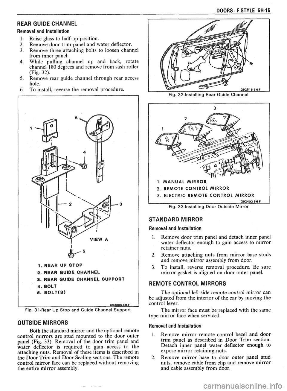
REAR GUIDE CHANNEL
Removal and lnstallation
1. Raise glass to half-up position.
2. Remove door trim panel and water deflector.
3. Remove three attaching bolts to loosen channel
from inner panel.
4. While pulling channel up and back, rotate
channel
180 degrees and remove from sash roller
(Fig.
32).
5. Remove rear guide channel through rear access
hole.
6. To install, reverse the removal procedure.
1, REAR UP STOP
2. REAR QUlDE CHANNEL
3. REAR GUIDE CHANNEL SUPPORT
4, BOLT
6. BObP(S)
Fig. 3 ?-Rear Up Stop and Guide Channel Support
OUTSIDE MIRRORS
Both the standard mirror and the optional remote
control mirrors are stud mounted to the door outer
panel (Fig.
33). Removal of the door trim panel and
water deflector is required to gain access to the
attaching nuts. Removal of these items is described in
the Door Trim and Door Sealing sections. The remote
control mirror face can be replaced without removing
the entire mirror assembly.
Fig. 32-Installing Rear Guide Channel
1. MANUAL MIRROR
2. REMOTE CONTROL MIRROR
3. ELECTRIC REMOTE CONTROL MIRROR
G92403-5H-F
Fig. 33-Installing Door Outside Mirror
STANDARD MIRROR
Removal and Installation
1. Remove door trim panel and detach inner panel
water deflector enough to gain access to mirror
retainer nuts.
2. Remove attaching nuts from mirror base studs
and remove mirror assembly from door.
3. To install, reverse removal procedure. Be sure
mirror gasket is aligned on door outer panel.
REMOTE CONTROL MIRRORS
The optional left side remote control mirror can
be adjusted from the interior of the car by moving the
control lever.
The mirror face must be replaced with the same
type mirror face when serviced.
Removal and Installation
1. Remove mirror remote control bezel and door
trim panel as described in Door Trim section.
Detach inner panel water deflector enough to
expose mirror retaining nuts.
-
2. Remove mirror base to door outer panel stud
nuts, remove cable from clip and remove mirror
and cable assembly from door.
Page 1754 of 1825
REAR END - I: STYLE 7H-11
COMPARTMENT WEATHERSTRIP
A clinch type weatherstrip is used on all styles.
The supersoft foam weatherstrip has an integral metal
reinforced section which grips and seals the
weatherstrip to the gutter flange.
Removal and lnstallation
1.
Separate butt joint at base of opening. Remove
and retain plug from old weatherstrip.
2. Peel weatherstrip from gutter flange toward
lower corners and then around complete opening.
3. To install, apply weatherstrip to pinchweld flange
and begin inserting center of weatherstrip
(marked with paint) onto the gutter flange at the
forward center of the opening between hinges. Be
sure clinch is completely seated to the flange
around the entire opening.
4. Cement butt ends together using plug from
original weatherstrip.
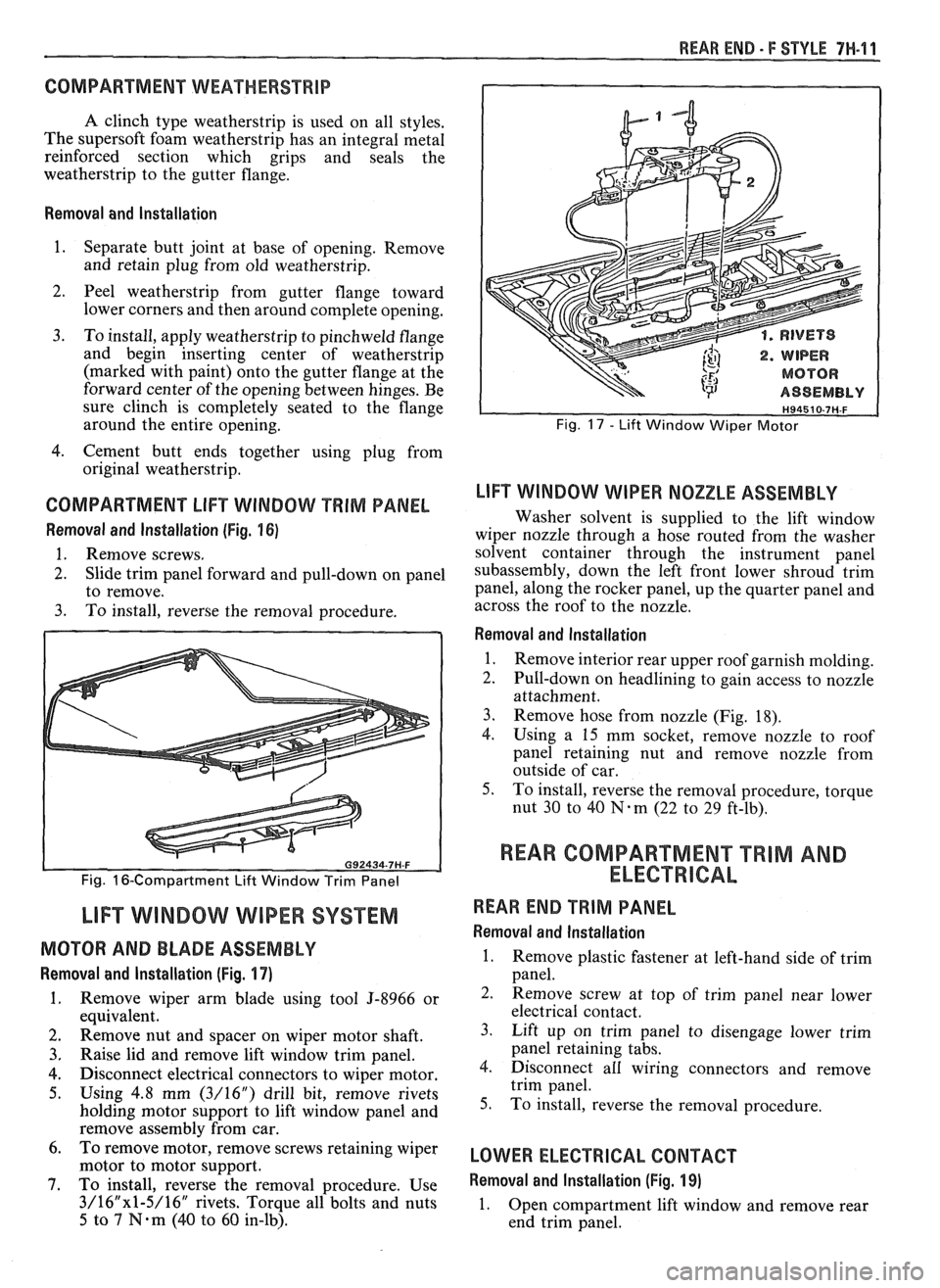
COMPARTMENT LlFT WINDOW PRIM PANEL
Removal and lnstallation (Fig. 16)
1. Remove screws.
2. Slide trim panel forward and pull-down on panel
to remove.
3. To install, reverse the removal procedure.
Fig. 16-Compartment Lift Window Trim Panel
LIFT WINDOW WIPER SYSTEM
MOTOR AND BLADE ASSEMBLY
Removal and lnstallation (Fig. 17)
1. Remove wiper arm blade using tool 5-8966 or
equivalent.
2. Remove nut and spacer on wiper motor shaft.
3. Raise lid and remove lift window trim panel.
4. Disconnect electrical connectors to wiper motor.
5. Using 4.8 mm (3/16") drill bit, remove rivets
holding motor support to lift window panel and
remove assembly from car.
6. To
remove motor, remove screws retaining wiper
motor to motor support.
7. To install, reverse the removal procedure. Use
3/16"x1-5/16" rivets. Torque all bolts and nuts
5 to 7 N.m (40 to 60 in-lb).
. RIVETS
. WIPER
MOTOR
ASSEMBLY
Fig. 17 - Lift Window Wiper Motor
LlFT WINDOW WIPER NOZZLE ASSEMBLY
Washer solvent is supplied to the lift window
wiper nozzle through a hose routed from the washer
solvent container through the instrument panel
subassembly, down the left front lower shroud trim
panel, along the rocker panel, up the quarter panel and
across the roof to the nozzle.
Removal and lnstallation
1.
Remove interior rear upper roof garnish molding.
2. Pull-down on headlining to gain access to nozzle
attachment.
3. Remove hose from nozzle (Fig. 18).
4.
Using a 15 mm socket, remove nozzle to roof
panel retaining nut and remove nozzle from
outside of car.
5. To install, reverse the removal procedure, torque
nut
30 to 40 N-m (22 to 29 ft-lb).
REAR COMPARTMENT "TRIM AND
ELECTRICAL
REAR END TRIM PANEL
Removal and lnstallation
1. Remove plastic fastener at left-hand side of trim
panel.
2. Remove screw at top of trim panel near lower
electrical contact.
3. Lift up on trim panel to disengage lower trim
panel retaining tabs.
4. Disconnect all wiring connectors and remove
trim panel.
5. To install, reverse the removal procedure.
LOWER ELECTRICAL CONTACT
Removal and lnstallation (Fig. 19)
1.
Open compartment lift window and remove rear
end trim panel.