1988 PONTIAC FIERO door lock
[x] Cancel search: door lockPage 22 of 1825
MAINTENANCE AND LUBRICATION OB-5
Throttle linkage inspection -- Inspect for inter-
ference, binding, damaged or missing parts.
Engine drive belts inspection - Inspect all
belts for cracks, fraying and wear. Adjust or replace as
needed.
Rear axle service (if equipped) - Check gear
lubricant level and add if needed. For cars equipped with a
limited slip rear axle, fluid does not require changing
(except Caprice and Corvette
- change fluid and required
additive at first
7,500 miles (12 500 km). See your
Owner's Manual or "Recommended Fluids
& Lubricants
Chart" in this section.
IF YOU USE YOUR GAR TO PULL A TRAILER,
CHANGE GEAR LUBRICANT EVERY 7,500 MILES
(12 500 KM).
NOTICE: A large loss in this system may indicate a
problem. Have it inspected and repaired at once.
Power antenna - Clean and then lubricate power
antenna mast. The proper lubricant as shown in Figure
OB-2 should be used.
AT LEAST ONCE A YEAR
Lap and shoulder belts condition and opera-
tion
- Inspect belt system, including webbing, buckles,
latch plates, retractors, guide loops and anchors.
Moveable head restraint operation - On cars
with moveable restraints, make sure restraints stay in the
desired position. (See adjustment instructions in your
Owner's Manual.)
Seatback latch and recliner operation on
cars equipped
with recliner seat --- Be sure seat-
backs latch on those cars with folding seats using mechan-
ical latches. Make sure the recliner is holding by pushing
and pulling on the top of the
seatback while it is reclined.
See your Owner's Manual for seat operating information.
Spare tire and jack storage- Be alert to rattles
in rear of car. Make sure the space tire, all jacking equip-
ment, any tire inflator and any covers or doors are securely
stowed at all times. Oil jack ratchet or screw mechanism
after each use.
Key lock service - Lubricate key lock cylinder at
least annually.
Body lubrication service - Lubricate all body
door hinges including the tailgate or hatchback lid (if
equipped). Also lubricate the body hood, fuel door and
rear compartment hinges and latches including interior
glove box and counsel doors, and any folding seat
hardware.
"Fansmissionltransaxle neutral or clutch
starl switch operation
CAUnON: Before pedorming the follow-
ing safety switch check, be sure to have
enough room around the car. Then, firmly
apply both the parking brake (see your
Owner's Manual for procedure) and the
regular brakes. Do not use the accelerator pedal.
If the engine
starls, be ready to turn
off the ignition promptly. Take these pre-
cautions because the car could move
without warning and possibly cause per-
sonal injury or properly damage. On auto-
matic transmissionltransaxle cars, try to
starl the engine in each gear. The starler
should crank only in "Park" or "Neutral."
On manual transmissionltransaxle cars,
place the
shiR lever in "Neutral," push the
clutch halfway and try to starl. The starler
should crank only when the clutch is fully
depressed.
Steering column lock operation
- While
parked, try to turn key to "Lock" in each gear range. The
key should turn to "Lock" only when gear is in "Park" on
automatic or "Reverse" on manual
transmissionltransax-
le. On cars with key release lever, try to turn key toULock"
without depressing the lever. The key should turn to
"Lock" only with the key lever depressed. On all vehicles,
the key should come out only in "Lock."
Parking brake and transmissionltransaxle
"Park" mechanism operation
CAUT1ON:Before checking the holding
ability of the parking brake and automatic
transmissionltransaxle "Park" mecha-
nism, park on a fairly steep hill with
enough room for movement in the down-
hill direction. To reduce the risk of person-
al injury or property damage, be prepared
to apply the regular brakes promptly if the
car begins to move.
To check the parking brake, with the engine running and
transmission/transaxle in "Neutral." slowly remove foot
pressure from the regular brake pedal (until the car is held
by only the parking brake).
To check the automatic transmissionltransaxle "Park"
mechanism holding ability, release all brakes after shift-
ing the transmissionltransaxle to "Park."
ljnderbody flushing - At least every spring,
tlush from the underbody with plain water any corrosive
materials used for ice and snow removal and dust control.
Take care to thoroughly clean any areas where mud and
other debris can collect.
Sediment packed in closed areas
of the vehicle should be loosened before being flushed.
Engine cooling system service - Inspect
coolant and freeze protection. If dirty or rusty, drain, flush
and refill with new coolant. Keep coolant
at the proper
mixture as specified in your Owner's Manual. This pro-
vides proper freeze protection. corrosion inhibitor level
and engine operating temperature. Inspect hoses and re-
place if cracked. swollen or deteriorated. Tighten hose
clamps. Clean outside of radiator and air conditioning
condensor. Wash radiator filler cap and neck.
To help
ensure proper operation. a pressure test of both the cooling
system and cap is also recommended. (See maintenance
schedule charts in Figure
OB-l for the recommended
coolant change interval.)
Page 23 of 1825
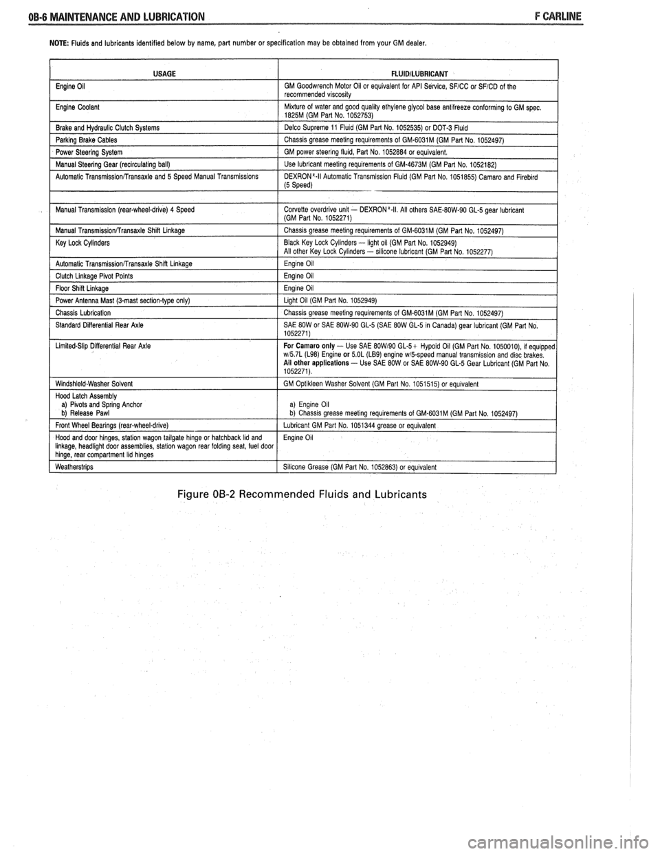
NOTE: Fluids and lubricants identified below by name, part number or specification may be obtained from your GM dealer.
Figure 00-2 Recommended Fluids and Lubricants
USAGE
Engine
Oil
Engine Coolant
Brake and
Hydraul~c Clutch Systems
Parking Brake Cables
Power Steering System
Manual
Steerlng Gear (reclrculat~ng ball)
Automatic
Transrn~ssionRransaxle and 5 Speed Manual Transm~ss~ons
Manual Transm~ssion (rear-wheel-drive) 4 Speed
Manual
Transm~ss~onRransaxle Shin Linkage
Key Lock Cylinders
Automatic Transmlss~onfrransaxle Shlft Llnkage
Clutch Llnkage Plvot Po~nts
Floor Sh~n L~nkage
Power Antenna Mast (3-mast sect~on-type only)
Chass~s Lubr~cation
Standard D~fferent~al Rear Axle
L~m~ted-Sl~p D~flerent~al Rear Axle
W~ndsh~eld.Washer Solvent
Hood Latch Assembly
a)
Plvots and Sprlng Anchor
b) Release Pawl
Front Wheel Bearings
(rearqwheel-drive)
Hood and door hlnges, statlon wagon tailgate hlnge or hatchback Ild and Ilnkage, headl~ght door assembl~es, statlon wagon rear foldrng seat, fuel door hlnge, rear compartment Ihd hlnges
Weatherstr~ps
FLUlDlLUBRlCANT
GM Goodwrench Motor 011 or equivalent for API Se~lce, SFICC or SFICD of the
recommended v~scos~ty
M~xture of water and good qual~ty ethylene glycol base antllreeze conforming to GM spec 1825M (GM Part No 1052753)
Delco Supreme 11
Fluld (GM Part No 1052535) or DOT-3 Fluld
Chass~s grease meetlng requirements of GM-6031M (GM Part No 1052497)
GM power
steerlng flu~d, Part No 1052884 or equivalent
Use lubricant meetlng requirements of GM-4673M (GM Part No 1052182)
DEXR0N'-II Automat~c Transm~ss~on Flu~d (GM Part No 1051855) Camaro and Flreblrd (5 Speed)
Corvette overdr~ve unlt - DEXRON a.II All others SAE-80W-90 GL-5 gear lubr~cant (GM Part No 1052271)
Chass~s grease meetlng requirements of GM-6031M (GM Part No 1052497)
Black Key Lock
Cyl~nders - light oil (GM Par1 No. 1052949)
All other Key Lock Cyl~nders - sllicone lubrlcant (GM Part No 1052277)
Eng~ne 011
Eng~ne 011
Eng~ne 011
Llght 011 (GM Part No 1052949)
Chass~s grease meetlng requirements of GM-6031M (GM Part No 1052497)
SAE
80W or SAE 80W-90 GL-5 (SAE 80W GL-5 In Canada) gear lubricant (GM Part No
1052271)
For Camaro only
- Use SAE BOW190 GL-5+ Hypold 011 (GM Part No 1050010), 11 equ~pped wl5 7L (L98) Englne or 5 OL (LB9) engine wmpeed manual transm~ss~on and disc brakes
All other applications - Use SAE 80W or SAE 80W-90 GL-5 Gear Lubr~cant (GM Part No
1052271)
GM
Opt~kleen Washer Solvent (GM Part No 1051515) or equ~valent
a) Eng~ne 011 b) Chass~s grease meet~ng requirements of GM.6031M (GM Part No 1052497)
Lubricant GM Part No 1051344 grease or equivalent
Eng~ne 011
S~l~cone Grease (GM Part No 1052863) or equivalent
Page 48 of 1825
AIR CONDITIONING 113-5
DIAGNOSIS
TESTING THE REFRIGERANT SYSEEM
If a malfunction in the refrigerant system is sus-
pected, check the following:
1. Check outer surfaces of radiator and condenser
cores to be sure air flow is not blocked by dirt,
leaves or other foreign material. Be sure to
check between the condenser and radiator as
well as the outer surfaces.
2. Restrictions or kinks in the condenser core,
hoses, tubes, etc.
3. Blower fan operation (see Section 8A).
4. Check all air ducts for leaks or restrictions. Low
air flow rate may indicate a restricted evaporator
core.
5. Compressor clutch slippage.
6. Improper drive belt tension.
7. See C.C.O.T. AIC system diagnostic
procedures.
InsufFicient Cooling "Quick-Check"
Procedure
The following "HAND-FEEL" procedure can
be used to approximate whether or not the
AIC system
has the proper charge of Refrigerant- 12 (providing air
temperature is above
2 1°C [70°F])on most models. This check can
be made in a matter of minutes and
may simplify system diagnosis by pinpointing the
problem to the amount of
W- 12 charge in the system or
by eliminating low charge possibility from the overall
checkout.
1. Engine must be
warm(CH0KE OPEN and OFF
FAST IDLE SPEED CAM) and at normal idle
speed.
2. Hood and body doors open.
3. Selector (mode) button set at "NORM."
4. Temperature lever at full COLD.
5. Blower on "HI."
6. "Hand-Feel" temperature of evaporator inlet
pipe after orifice, and accumulator surface, with
compressor engaged.
BOTH SAME TEMPERATURE AND
BOTH SAME DEGREE COOLER
THAN AMBIENT
- Proper condition:
check for other problems; (see Testing the
Refrigerant System).
@ Leak check. If leak found, dis-
charge and repair as required. Evac-
uate and recharge.
e If no leak found, see A/C System
Diagnostic Procedures.
EVAPORATOR
'MODE POSITION
INDICATED
BY (
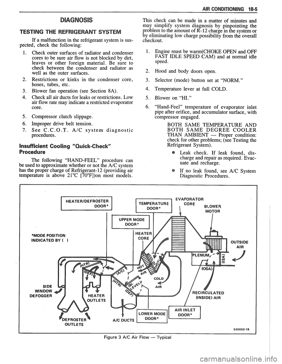
Figure 3 AIC Air Flow --- Typical
Page 114 of 1825
CHASSIS SHEET METAL 2@-7
3. During the above flash time period (1 to 10 min-
utes), apply appropriate "conventional" interior acrylic lacquer color as required and allow
painted part to dry for
4 to 5 hours before install-
ing on car.
RlGlD OW HARD ABS PMS"TIC PARTS
Rigid or hard ABS plastic requires no primer.
"Conventional" interior acrylic lacquers adhere satis-
factorily to hard ABS plastics.
Procedure
1. Wash part thoroughly with a cleaning solvent
(Acrylic-Clean, Pre-Kleano, Prep-Sol or equiv-
alent) to remove any dirt or grease.
2. Apply appropriate "conventional" interior
acrylic lacquer color. Apply only sufficient
color for proper hiding to avoid washout of
"grain" effect.
3. Allow to dry and then install part.
VINYL AND FLEXIBLE (Son) ABS
PLASTIC PARTS
The outer cover or skin material of "flexible"
instrument panel cover (pad) assemblies is made of an
ABSIPVC plastic blend. The same is true of many
"padded" door trim assemblies. The soft cushion pad-
ding under the I.P. skin is urethane foam plastic. The
most widely used
"flexible" vinyls (poly vinyl chlo-
ride)
are coated fabrics, such as used in seat trim,
some door trim assemblies, molded headlining panels
and sun visors. Most head rests are "flexible" vinyls.
Examples of "hard vinyls are: door and front seat
back assist handles and coat hooks.
The paint system of vinyl and flexible ABS
plastic involves the use of interior "vinyl" color and a
clear vinyl top coat.
Procedure
1. Wash part thoroughly with a vinyl cleaning and
preparation solvent ("Vinyl Press"
- Ditzler,
"Vinyl Prep Conditioner"
- Detroit Autobody
or equivalent) to remove greasy film or silicone.
Wipe off cleaner while still wet with clean,
lint-
free cloth.
2. Immediately after wiping face dry, apply inte-
rior "vinyl" color in wet coats allowing suffi-
cient flash time between coats (see label
directions on can). Use proper "vinyl" color as
designated by interior trim combinations. Apply
only sufficient color for proper hiding to avoid
washout of "grain" effect. No primer or
primer-
sealer is required.
3. Before the final vinyl color coat has dried, apply
two coats of clear vinyl top coat spray (instru-
ment panels will require the "nonglare" clear top
coat). Do not allow the first spray coat to com-
pletely dry before spraying on the second. Use
top coat with appropriate gloss level to match adjacent similar components. This
clear coat is
necessary to control the gloss requirement and
prevent
'tracking" (rubbing-off) of the color
coat after drying.
4. Allow to dry according to label directions before
installing part.
ON-VEHICLE SERVICE
CONCEALED HEADLIGHTS
The concealed headlights used on this model are
electrically operated. When the headlights are turned
on, solid state circuitry activates the actuators. This
same circuitry senses when the actuators stop moving
and removes the ground to deactivate the actuators.
When the headlights are turned off, the actuators run
in opposite direction closing the headlight doors.
Should an electrical failure occur in the head-
light circuit, they may be raised manually by rotating
the knob on the actuator in a counterclockwise direc-
tion until the headlights are fully open. The headlights
may be lowered by rotating the knob on the actuator in
a clockwise direction until the headlights are fully
closed.
For electrical circuit information and diagnosis,
refer to Section
8A of this manual.
If it is desired to raise the headlights with the
lights off, either of the following procedures may be
used:
1. Turn the lights on. After the headlights are
open, disconnect the electrical connections at
the actuator connectors. Turn the lights off. The
headlights will now remain in the open position.
2. Turn the parking lights on. Depress the head-
light rocker switch lightly. The headlights may
then be raised "up" fully with the lights off.
Adjust
Because of the number of adjustments possible
and the number of attaching points of the concealed
headlight body assembly
(9), only those attachments
which control the adjustment desired should be loos-
ened. Make one
adjbstment at a time.
NOTICE: The headlight door does NOT have
slotted mounting holes and therefore is not
adjustable by itself. This insures proper clearance
between the headlight door and the hood and
fenders in both the raised and lowered positions.
The entire headlight body assembly must be
adjusted to achieve the desired appearance and
fit. Care should be exercised when adjusting the
headlight body assembly. Severe hammer blows could damage the die cast aluminum headlight
body assembly.
TO RAISE OR LOWER the headlight body
assembly, proceed as follows:
1. Open hood.
2. Raise headlights.
Page 132 of 1825
STEERING, SUSPENSION, TIRES AND WHEELS DIAGNOSIS 3-7
e To determine if turn signal switch is inoperative,
substitute new turn signal switch into circuit and
operate switch by hand.
If the car's lights operate
normally, turn signal switch is inoperative.
Front Or Rear Turn Signal Lights Not Flashing
Inspect
s Burned-out or damaged turn signal bulb
e High resistance conection to ground at bulb
socket
s Loose chassis-to-column connector. Disconnect
column-to-chassis connector and connect new
turn signal switch into system and operate switch
by hand.
A. If turn signal lights are now on and flashing,
turn signal switch is inoperative.
B. If car lights do not operate, refer to Section
8A
for electrical diagnosis.
Turn Indicator Panel Lights
Inspect
Burned out bulbs or opens, grounds in the wiring
harness from the front turn signal bulb socket to the
indicator lights. Refer to Section
8A for electrical
diagnosis.
Stop Light Mot On When Turn Indicated
Inspect
s Loose column-to-chassis connection
e Disconnect the column-to-chassis connector and
connect the new turn signal switch into the
system and operate the switch by hand.
A. If the brake lights work when the switch is
in the turn position, the turn signal switch
is inoperative.
B. If the brake lights do not work, refer to Section
8A for electrical diagnosis.
Turn Signal Lights Flash Very Slowly
e Loose chassis-to-column connection
a Disconnect the column-to-chassis connector and
connect a new turn signal switch into the system
and operate the switch by hand.
A. If the lights flash at a normal rate, the turn
signal switch is inoperative.
B. If the Lights still flash very slowly, refer to
Section
8A for electrical diagnosis.
Hazard Signal Lights Will Not Flash - Turn
Signal Functions Normally
~"SPBC~
a Blown fuse
Inoperative hazard warning flasher
e Loose chassis-to-column connection
s Disconnect the column-to-chassis connector and
connect a new turn signal switch into the system,
then press in the hazard warning button and
watch the hazard warning lights.
A. If the lights now work normally, the turn
signal switch is inoperative.
B. If the lights do not flash, check the wiring
harness. Refer to Section
8A for electrical
diagnosis.
IGNITION SWITCH
Electrical System Will Not Function
Damaged ign~rion switch
e Ignition switch not adjusted properly
e Loose connector at the ignition switch
Switch Will Not Turn
Inspect
Damaged ignition switch
Switch Cannot Be Set Correctly
Inspect
Switch actuator rod deformed
e Sector to rack engaged in wrong tooth
KEY REMINDER
Figs. 1 through 11 ,
Weminder Continues To Operate With Key Out,
But Stops When Driver's Door Is Closed
e Chips, foreign material in lock cylinder bore
Sticky lock cylinder actuator tip
Damaged or broken reminder switch
Reminder Does Not Sound With Key Fully
Inserted In Lock Cylinder And The Driver's Door
Open
Inspect
1. Power not available to reminder. Refer to Sec-
tion
8A for electrical diagnosis.
2. Open in chassis wiring. Check by separating
chassis-to-column connector. Connect terminals
"E" and "F" female contacts on the chassis
connector (a bent paper clip will work). If the
reminder sounds, repair chassis wiring. If the
reminder does not sound, go to Step
A.
A. Connect a continuity meter (light) to the
male
"E" and "F" column connector
contacts. Push the key all the way into the
lock cylinder. If the light is on when the key
Page 135 of 1825

3-10 STEERING, SUSPENSION, TIRES AND WHEELS DIAGNOSIS
Reminder Keeps Operating With Key In Lock
Cylinder, Driver's Door Open Or Closed; Ceases
When Key Is Removed
Inspect
s Door jamb switch on driver's side misadjusted or
inoperative.
e Wire from signal switch to door jamb switch
shorted.
A. This condition indicates the lock cylinder or
the reminder switch is at fault. To verify,
check for continuity at the
"E" and "F"
male column connector contacts, with the
key removed from the lock cylinder. If
continuity exists, the fault is in the column.
B. Insert the key into the lock, then turn the
lock toward the "Start" position. If the
reminder stops when the key is in the
"Run" position or when it is turned past
"Run" toward "Start," the problem is a
sticky lock cylinder actuator.
COLUMN-MOUNTED DIMMER SWITCH
No "Low" or "High" Beam
Inspect
e Loose connector at dimmer switch
e Improper adjustment
e Internally damaged or worn switch. Check the
continuity on the switch at the It. green and at the
tan switch terminals by pushing in the plunger all
the way.
A click should be heard. If there is no
continuity, replace the dimmer switch. If there is
continuity, refer
to'section 8A for electricaldiag-
nosis.
PIVOT AND SWITCH ASSEMBLY
Switch Inoperative: No "Low," "High" and/or
"Wash"
e Loose body-to-switch connector
a Broken or damaged switch
Internally damaged or worn switch. Connect a
new switch without removing the old one. If the
system functions, replace the switch. If the
system doesn't function, refer to Section
8A for
electrical diagnosis.
STEERING GEAR AND PUMP LEAKS
General Procedure
Inspect
s Overfilled reservoir
s Fluid aeration and overflow
e , Hose connections
Verify exact point of leakage Example:
Torsion bar, stub shaft and
adjuster seals are close together; the exact
spot where the system is leaking may not be
clear.
Example: The point from which the fluid is
dripping is not necessarily the point where
the system is leaking; fluid overflowing from
the reservoir, for instance.
e When service is required:
A. Clean leakage area upon disassembly.
B. Replace leaking seal.
C. Check component sealing surfaces for
damage.
D. Reset bolt torque to specifications, where
required.
Some complaints about the power steering system
may be reported as:
A. Fluid leakage on garage floor
B. Fluid leaks visible on steering gear or pump
C. Growling noise, especially when parking or
when engine is cold
D. Loss of power steering when parking
E. Heavy steering effort
When troubleshooting these kinds of complaints,
check for an external leak in the power steering system.
For further diagnosis of leaks, refer to External
Leakage Check in this section.
External Leakage Check
Fig. 12
The purpose of this procedure is to pinpoint the
location of the leak.
In some cases, the leak can easily be located. But,
seepage-type leaks may be more difficult to isolate. To
locate seepage leaks, use the following method.
1. With the engine off, wipe dry the complete power
steering system.
2. Check the fluid level in the pump's reservoir. Add
fluid if necessary.
3. Start the engine, then turn the steering wheel
from stop to stop several times. Do not hold it at
a stop for any length of time, as this can damage
the power steering pump. It is easier if someone
else operates the steering wheel while you search
for the seepage.
4. Find the exact area of the leak and repair leak.
SEAL REPLACEMENT
RECOMMENDATIONS
Lip seals, which seal rotating shafts, require
special treatment. This type of seal is used on the
steering gear and on the drive shaft of the pump. When
there is a leak in one of these areas, always replace the
seal(s), after inspecting and thoroughly cleaning the
sealing surfaces. Replace the shaft only if very severe
pitting is found. If the corrosion in the lip seal contact
zone is slight, clean the surface of the shaft with crocus
cloth. Replace the shaft only if the leakage cannot be
stopped by first smoothing with crocus cloth.
Page 557 of 1825
6EZ-C1-2 5.OL (VIN E) DRIVEABILITY AND EMISSIONS
PROM CARRIER
PROM (ENGINE CALIBRATOR)
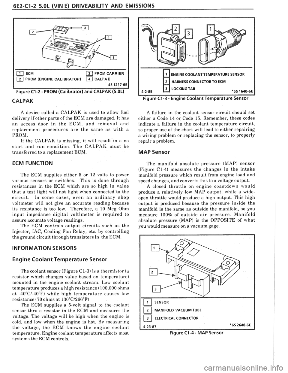
Figure C1-2 - PROM (Calibrator) and CALPAK (5.OL)
CALPAK
ENGINE COOLANT TEMPERATURE SENSOR
HARNESS CONNECTOR TO ECM
LOCKING TAB
4-2-85
*5S 1640-6E
Figure C1-3 - Engine Coolant Temperature Sensor
A device called a CALPAK is used to allow fuel
A failure in the coolant sensor circuit should set
delivery if other parts of the ECM are damaged. It has
either a Code 14 or Code 15. Remember, these codes
an access door in the ECM, and removal and
indicate a failure in the coolant temperature circuit,
replacement procedures are the
same as with a
so proper use of the chart will lead to either repairing
PRO;\/I. a wiring problem or replacing the sensor, to properly
If the CALPAK is missing, it will result in a no
repair a problem.
start
i111d run condition. The CALPAK must be
transferred to a replacement ECM.
MAP Sensor
ECM FUNCTION
The ECM supplies either 5 or 12 volts to power
various sensors or switches. This
is done through
resistances in the ECM which are so high in value
that a test light will not light when connected to the
circuit. In some cases, even an ordinary shop
voltmeter will not give an accurate reading because
its resistance is too low. Therefore, a 10 Meg Ohm
input impedance digital voltlmeter is required to
assure accurate voltage readings.
The ECM controls output circuits such as the
Injector, IAC, Cooling Fan Relay, etc. by controlling
the ground circuit through transistors in the ECM.
INFORMATION SENSORS
Engine Coolant Temperature Sensor
The coolant sensor (Figure C1-3) is a thermistor (a
resistor which changes value based on temperature)
mounted in the engine coolant stream.
[,ow coolant
temperature produces a high resistance
( 100,000 ohms
at
-40°C/-40°F) while high temperature causes low
resistance
(70 ohms at 13O0C/266"F)
The ECM supplies a 5-volt signal to the cooliint
sensor thru a resistor in the ECM and measures the
voltage. The voltage will be high when the engine is
cold,
and low when the engine is hot. By measuring
the voltage, the ECM knows the engine coolant
temperature. Engine coolant temperature affects most
systems the ECM controls. The
manifold absolute pressure
(MAP) sensor
(Figure
(21-4) measures the changes in the intake
manifold pressure which result from engine load and
speed changes, and converts this to a voltage output.
A closed throttle on engine coastdown would
produce a relatively low
MAP output, while a wide-
open throttle would produce a high output. This high
output is produced because the pressure inside the
manifold is the same as outside the manifold, so you
measure 100% of outside air pressure. Manifold
absolute pressure (MAP) is the OPPOSITE of what
you would measure on a vacuum gage.
SENSOR
MANIFOLD VACUUM TUBE
ELECTRICAL CONNECTOR
Figure C1-4 - MAP Sensor
Page 639 of 1825
6E2-C14-2 DRIVEABILITY AND EMISSIONS - 5.OL (VIN E)
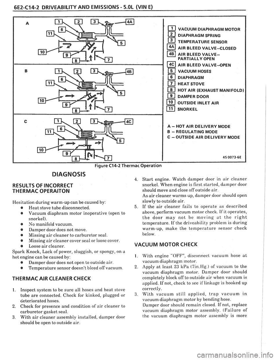
Figure C14-2 Thermac Operation
VACUUM DIAPHRAGM MOTOR
DIAPHRAGM
SPRING
TEMPERATURE SENSOR
a AIR BLEED VALVE-CLOSED - AIR BLEED VALVE- PARTIALLY OPEN
AIR BLEED VALVE-OPEN
VACUUM HOSES
DIAPHRAGM
a HEAT STOVE
HOT
AIR (EXHAUST MANIFOLD)
DAMPER
DOOR
OUTSIDE INLET AIR
11 SNORKEL r"l
A - HOT AIR DELIVERY MODE
B - REGULATING MODE
C
--OUTSIDE AIR DELIVERY MODE
DIAGNOSIS
4.
RESULTS OF INCORRECT
THERMAC OPERAITON
Hesitation during warm-up can be caused by:
r Heat stove tube disconnected. 5.
r Vacuum diaphram motor inoperative (open to
snorkel).
@ No manifold vacuum.
Damper door does not move.
Missing air cleaner to carburetor seal. Start
engine. Watch damper door in air cleaner
snorkel. When engine is first started, damper door
should move and close off outside air.
As air cleaner warms up, damper door should open
slowly to outside air.
If the air cleaner fails to operate as described
above, perform vacuum motor check. If it operates,
the door may not be moving
at the right
temperature. If the driveability
problem is during
warm-up, make the temperature sensor check
below.
- @ Missing air cleaner cover seal or loose cover.
r Loose air cleaner. VACUUM MOTOR CHECK
Spark Knock, Lack of power, sluggish, or spongy, on a
hot engine can be caused by: I. With engine "OFF", disconnect vacuum hose at
@ Damper door does not open to outside air. vacuum
diaphragm motor.
@ Temperature sensor doesn't bleed off vacuum. 2. Apply at least 23 kPa (7in.fIg.) of vacuum to the
vacuum diaphragm motor. Damper door should
THERMAC AIR CLEANER CHECK completely block off to outside air when vacuum is
applied. If not, check to see if linkage is hooked up
. .
1. Inspect system to be sure all hoses and heat stove correctly.
tube are connected. Check for kinked, plugged or 3. With vacllum still applied, trap Vacuum in
deteriorated
hoses. vitcuum diaphragm motor by bending hose.
2. Check for presence and condition of air cleaner to Ilarnper door should remain closed. If not, replace
carburetor gasket seal. vacuum
diaphragm motor assembly. (Failure of
3. With air cleaner assembly installecl, damper door the
vacuum diaphragm motor assembly is more
should be open to outside air.