1988 PONTIAC FIERO spare wheel
[x] Cancel search: spare wheelPage 21 of 1825
OB-4 MAINTENANCE AND LUBRICATION
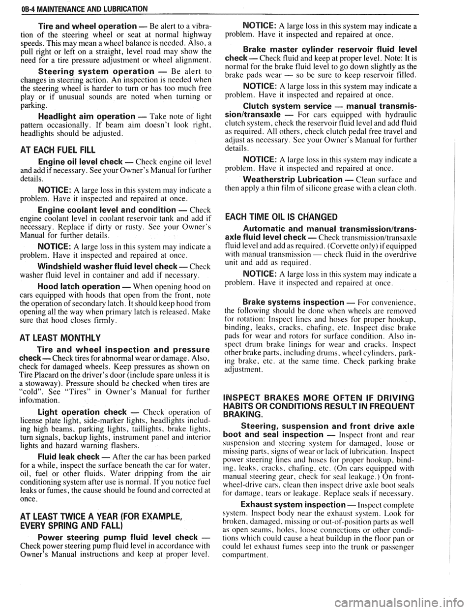
Tire and wheel operation - Be alert to a vibra-
tion of the steering wheel or seat at normal highway
speeds. This may mean a wheel balance is needed. Also, a
pull right or left on a straight, level road may show the
need for
a tire pressure adjustment or wheel alignment.
Steering system operation - Be alert to
changes in steering action. An inspection is needed when
the steering wheel is harder to turn or has too much free
play or if unusual sounds are noted when turning or
parking.
Headlight aim operation - Take note of light
pattern occasionally. If beam aim doesn't look right,
headlights should be adjusted.
AT EACH FUEL FILL
Engine oil level check - Check engine oil level
and add if necessary. See your Owner's
Manual for further
details.
NOTICE: A large loss in this system may indicate a
problem. Have it inspected and repaired at once.
Engine coolant level and condition - Check
engine coolant level in coolant reservoir tank and add if
necessary. Replace if dirty or rusty. See your Owner's
Manual for further details.
NOTICE: A large loss in this system may indicate a
problem. Have it inspected and repaired at once.
Windshield washer fluid level check -- Check
washer fluid level in container and add if necessary.
Hood latch operation - When opening hood on
cars equipped with hoods that open from the front, note
the operation of secondary latch. It should keep hood from
opening all the way when primary latch is released. Make
sure that hood closes firmly.
AT LEAST MONTI-ILY
Tire and wheel inspection and pressure
check--
Check tires for abnormal wear or damage. Also,
check for damaged wheels. Keep pressures as shown on
Tire Placard on the driver's door (include spare unless it is
a stowaway). Pressure should b\: checked when tires are
"cold". See "Tires" in Owner's Manual for further
infomation.
Light operation check - Check operation of
license plate light, side-marker lights, headlights includ-
ing high beams, parking lights, taillights, brake lights.
turn signals, backup lights, instrument panel and interior
lights and hazard warning flashers.
Fluid leak check - After the car has been parked
for a while, inspect the surface beneath the car for water,
oil, fuel or other fluids. Water dripping from the air
conditioning system after use is normal. If you notice fuel
leaks or fumes, the cause should be found and corrected at
once.
AT LEAST TWICE A YEAR (FOR EXAMPLE,
EVERY SPRING AND FALL)
Power steering pump fluid level check --
Check power steering pump fluid level in accordance with
Owner's Manual instructions and keep at proper level.
NOTICE: A large loss in this system may indicate a
problem. Have it inspected and repaired at once.
Brake master cylinder reservoir fluid level
check ---- Check fluid and keep at proper level. Note: It is
normal for the brake fluid level to go down slightly as the
brake pads wear
- so be sure to keep reservoir filled.
NOTICE: A large loss in this system may indicate a
problem. Have
it inspected and repaired at once.
Clutch system service --- manual transmis-
sionltransaxle --- For cars equipped with hydraulic
clutch system, check the reservoir fluid level and add fluid
as required. All others, check clutch pedal free travel and
adjust as necessary. See your Owner's Manual for further
details.
~
NOTICE: A large loss in this system may indicate a
problem. Have it inspected and repaired at once.
Weatherstrip Lubrication - Clean surface and
then apply a thin film of silicone grease with a clean cloth.
EACH TIME OIL IS CHANGED
Automatic and manual transmissionltrans-
axle fluid level check - Check transmission/transaxle
fluid level and add as required. (Corvette only) if equipped
with manual transmission
- check fluid in the overdrive
unit and add as required.
NOTICE: A large loss in this system may indicate a
problem. Have
it inspected and repaired at once.
Brake systems inspection - For convenience,
the following should be done when wheels are removed
for rotation: Inspect lines and hoses for proper hookup,
binding, leaks, cracks, chafing, etc. Inspect disc brake
pads for wear and rotors for surface condition. Also in-
spect drum brake linings for wear and cracks. Inspect
other brake parts, including drums, wheel cylinders, park-
ing brake, etc. at the same time. Check parking brake
adjustment.
INSPECT BRAKES MORE OFTEN IF DRIVING
HABITS OR CONDITIONS RESULT IN FREQUENT
BRAKING.
Steering, suspension and front drive axle
boot and seal inspection
- Inspect front and rear
suspension and steering system for damaged, loose or
missing parts, signs of wear or lack of lubrication. Inspect
power steering lines and hoses for proper hookup, bind-
ing, leaks, cracks, chafing, etc. (On cars equipped with
manual steering gear, check for seal leakage.) On
front-
wheel-drive cars, clean then inspect drive axle boot seals
for damage, tears or leakage. Replace seals if necessary.
Exhaust system inspection - Inspect complete
system. Inspect body near the exhaust system. Look for
broken, damaged, missing or out-of-position parts as well
as open seams, holes, loose connections or other condi-
tions which could cause a heat buildup in the tloor pan or
could let exhaust fumes seep into the trunk or passenger
compartment.
Page 117 of 1825
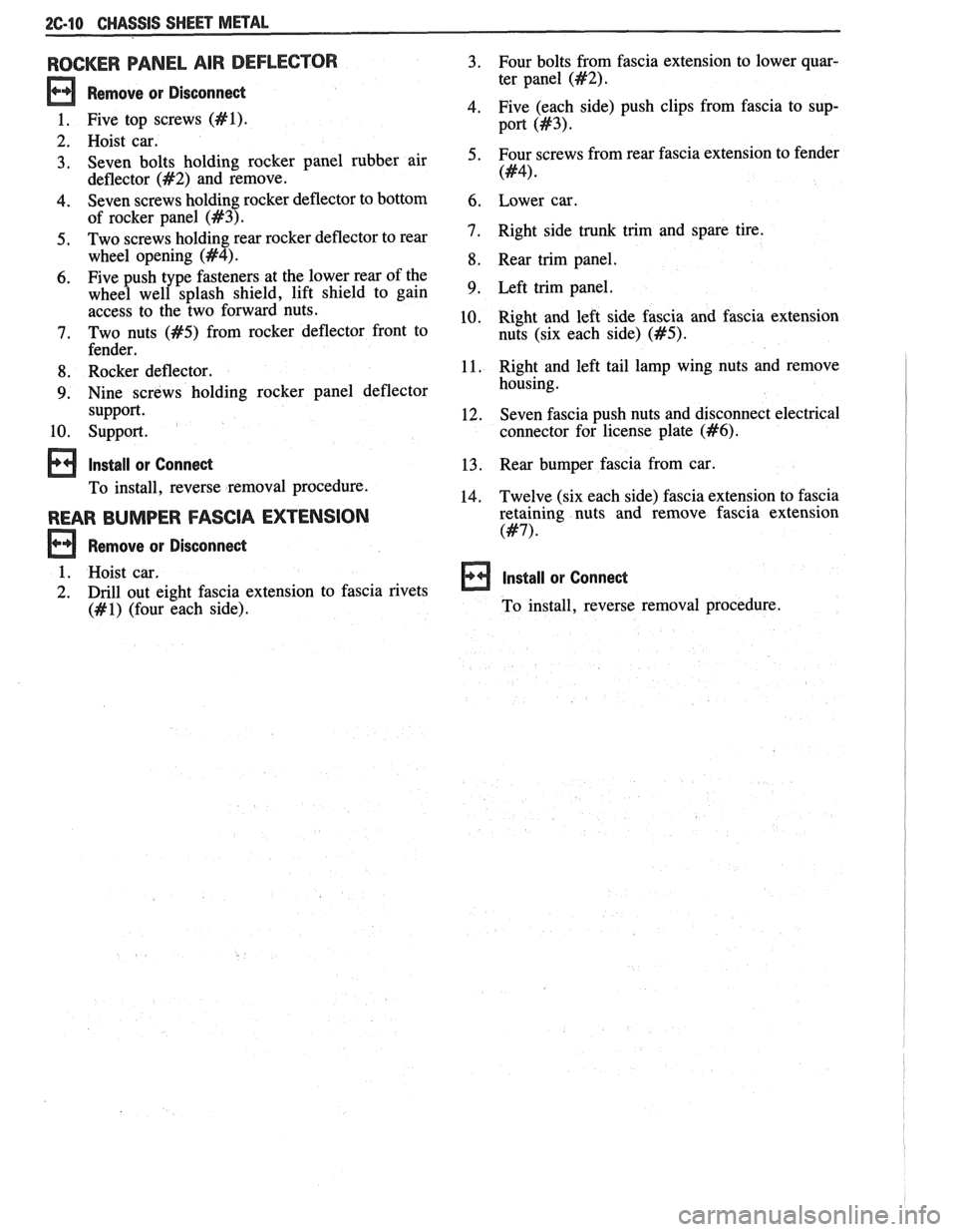
2C-10 CHASSIS SHEET METAL
ROCKER PANEL AIR DEFLECTOR
Remove or Disconnect
1. Five top screws (#I).
2. Hoist car.
3. Seven bolts holding rocker panel rubber
air
deflector
(#2) and remove.
4. Seven screws holding rocker deflector to bottom
of rocker panel
(#3).
5. Two screws holding rear rocker deflector to rear
wheel opening
(#4).
6. Five
push type fasteners at the lower rear of the
wheel well splash shield, lift shield to gain
access to the two forward nuts.
7. Two nuts (#5) from rocker deflector front to
fender.
8. Rocker deflector.
9. Nine screws holding rocker panel deflector
support.
10. Support.
Install or Connect
To install, reverse removal procedure.
REAR BUMPER FASCIA EXTENSION
Remove or Disconnect
1. Hoist car,
2. Drill out
eight fascia extension to fascia rivets
(#I) (four each side). Four
bolts from fascia extension to lower quar-
ter panel
(#2).
Five (each side) push clips from fascia to sup-
port
(443).
Four screws from rear fascia extension to fender
(#4).
Lower car.
Right side trunk trim and spare tire.
Rear trim panel.
Left trim panel.
Right and left side fascia and fascia extension
nuts (six each side)
(#5).
Right and left tail lamp wing nuts and remove
housing.
Seven fascia push nuts and disconnect electrical
connector for license plate
(#6).
Rear bumper fascia from car.
Twelve (six each side) fascia extension to fascia
retaining nuts and remove fascia extension
(#7).
Install or Connect
To install, reverse removal procedure.
Page 137 of 1825
3-1 2 STEERING, SUSPENSION, TIRES AND WHEELS DIAGNOSIS
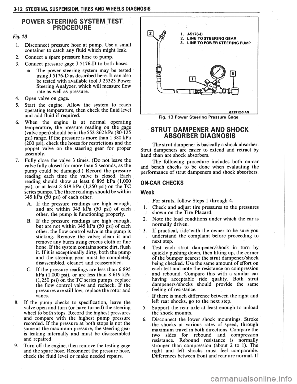
POWER STEERlNG SYSTEM "TEST
PROCEDURE
Fig. 13 1. J-5176-D 2. LlNE TO STEERING GEAR
1. Disconnect pressure hose at pump. Use a small 3. LINE TO POWER STEERING PUMP
container to catch any fluid which might leak.
2. Connect a spare pressure hose to pump.
3. Connect pressure gage
J 5176-D
to both hoses.
e The power steering system may be tested
using
J 5 176-D as described here. It can also
be tested with available tool
J 25323 Power
Steering Analyzer, which will measure flow
rate as well as pressure.
4. Open valve on gage.
5. Start the engine. Allow the system to reach
operating temperature, then check the fluid level
and add fluid if required.
6. When the engine is at normal operating
temperature, the pressure reading on the gage
(valve open) should be in the 552-862
kPa (80-125
psi) range. If the pressure is more than 1 380
kPa
(200 psi), check the hoses for restrictions and the
poppet valve on the steering gear for proper
assembly.
7. Fully close the valve 3 times. (Do not leave the
valve fully closed for more than 5 seconds, as the
pump could be damaged.) Record the pressure
reading each time the valve is closed. Each
reading should show at least 6 895
kPa (1,000
psi), or at least 8 619 kPa (1,250 psi) on the TC
series pumps. The three readings should be within
345
kPa (50 psi) of each other.
A. If the pressure readings are high enough,
and are within 345
kPa (50 psi) of each
other, the pump is functioning properly.
B. If the pressure readings are high enough,
but are not within 345
kPa (50 psi) of each
other, the flow control valve in the pump is
sticking. Remove the valve; clean it and
remove any burrs using crocus cloth or fine
hone. If the system contains some dirt, flush
it. If it is exceptionally dirty, both the pump
and the steering gear must be completely
disassembled, cleaned and reassembled.
C. If the pressure readings are less than
6 895
kPa (1,000 psi), or are less than 8 619 kPa
(1,250 psi) on the TC series pumps, replace
the flow control valve and recheck. If the
pressures are still low, replace the rotor and
vanes.
8. If the pump checks to specification, leave the
valve open and turn (or have turned) the steering
wheel to both stops. Record the highest pressures
and compare with the highest pump pressure
recorded. If the pressure at both stops is not the
same as the maximum pressure, the steering gear
is leaking internally and must be disassembled
and repaired.
9. Turn off the engine, then remove the testing gage
and the spare hose. Reconnect the pressure hose,
check the fluid level or make needed repairs.
Fig. 13 Power Steering Pressure Gage
STRUT DAMPENER AND SHOCK
ABSORBER DIAGNOSIS
The strut dampener is basically a shock absorber.
Strut dampeners are easier to extend and retract by
hand than are shock absorbers.
The following procedure includes both on-car
and bench checks to be done when evaluating the
performance of strut dampeners and shock absorbers.
ON-CAR CHECKS
Weak
For struts, follow Steps 1 through 4.
1. Check
and adjust tire pressures to the pressures
shown on the Tire Placard.
2. Note the load conditions under which the car is
normally driven.
3. If practical, ride with the owner to be sure you
understand the complaint before proceeding to
next step.
4. Test each strut
dampener/shock in turn by
quickly pushing down, then lifting up, the corner
of the bumper nearest the strut
dampener/shock
being checked. Use the same amount of effort on
each test and note the resistance on compression
and rebound. Compare this with a similar car
having acceptable ride quality. Both strut
dampeners/shocks should provide the same
feeling of resistance.
If there is much difference between the right and
left rear shocks, go to the next step.
5. Support the rear axle at least enough to unload
the shock mounts.
6. Disconnect the lower shock mountings. Stroke
the shocks at various rates of speed, through
maximum travel in both directions. Compare the
two sides for rebound and compression
resistance. Rebound resistance is normally
stronger than compression (about 2 to 1). The
right and left shocks must feel comparable.
Differences between front and rear are normal. If
Page 195 of 1825
387-2 POWER STEERING
The effect of improperly adjusted worm thrust
bearings or an improperly adjusted over-center preload
could cause a handling stability complaint.
To properly adjust the power steering gear, the
assembly MUST be removed from the vehicle and
adjustments performed as outlined.
For removal of the power steering gear assembly
see "Power Steering Gear".
DRIVE BELT TENSION
All drive belt tension specifications can be found
in the Engine Cooling Section 6B.
When adjusting a power steering pump belt,
never pry against the pump reservoir or pull against the
filler neck. Two systems are used for belt adjustment.
On some
models, the pump is loosened from the
bracket and moved outward to increase the tension. On
other models, a half-inch square drive hole is located
in the bracket, and this hole is used to rotate the
pump-and-bracket assembly outward to increase belt
tension.
Place belt tension gage, J-23600 or equivalent
midway between the pulleys on drive belt being
checked.
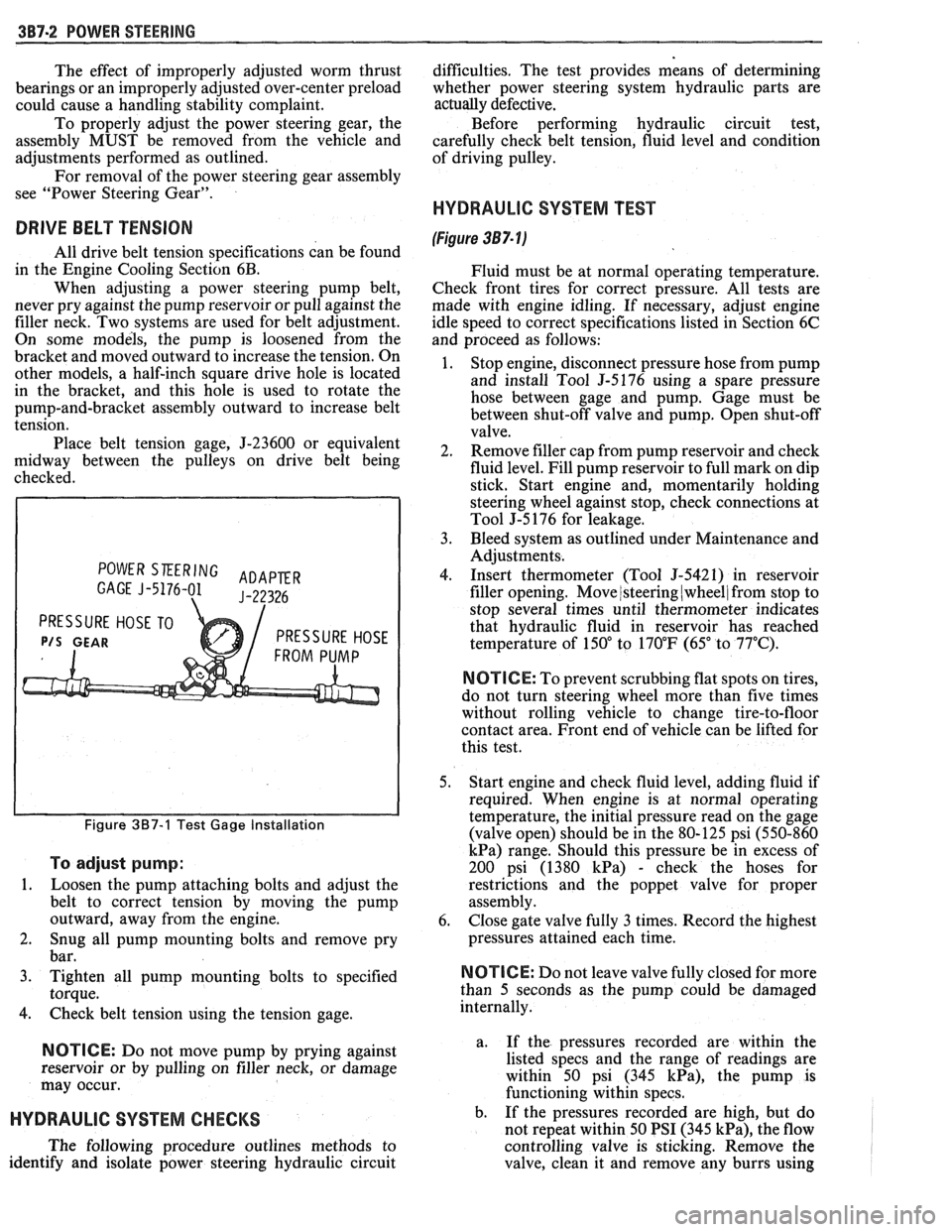
POWER SKERING ADAPER GAGE J-5176-01 J-22326
PRESSURE HOSE TO
P/S GEAR PRESSURE HOSE
Figure 387-1 Test Gage Installation
To adjust pump:
1.
Loosen the pump attaching bolts and adjust the
belt to correct tension by moving the pump
outward, away from the engine.
2. Snug all pump mounting bolts and remove pry
bar.
3. Tighten all pump mounting bolts to specified
torque.
4. Check belt tension using the tension gage.
NOTICE: Do not move pump by prying against
reservoir or by pulling on filler neck, or damage
may occur.
HYDRAULIC SYSTEM CHECKS
The following procedure outlines methods to
identify and isolate power steering hydraulic circuit difficulties.
The test provides means of determining
whether power steering system hydraulic parts are
actually
defective.
Before performing hydraulic circuit test,
carefully check belt tension, fluid level and condition
of driving pulley.
HYDRAULIC SYSTEM TEST
(Figure 387- lj
Fluid must be at normal operating temperature.
Check front tires for correct pressure. All tests are
made with engine idling. If necessary, adjust engine
idle speed to correct specifications listed in Section 6C
and proceed as follows:
1. Stop engine, disconnect pressure hose from pump
and install Tool
5-5176 using a spare pressure
hose between gage and pump. Gage must be
between shut-off valve and pump. Open shut-off
valve.
2. Remove filler cap from pump reservoir and check
fluid level. Fill pump reservoir to full mark on dip
stick. Start engine and, momentarily holding
steering wheel against stop, check connections at
Tool J-5 176 for leakage.
3. Bleed system as outlined under Maintenance and
Adjustments.
4. Insert thermometer (Tool J-5421) in reservoir
filler opening. Move
/steering (wheel/ from stop to
stop several times until thermometer indicates
that hydraulic fluid in reservoir has reached
temperature of
150" to 170°F (65" to 77°C).
N OTI G E: To prevent scrubbing flat spots on tires,
do not turn steering wheel more than five times
without rolling vehicle to change tire-to-floor
contact area. Front end of vehicle can be lifted for
this test.
5. Start engine and check fluid level, adding fluid if
required. When engine is at normal operating
temperature, the initial pressure read on the gage
(valve open) should be in the 80-125 psi (550-860
kPa) range. Should this pressure be in excess of
200 psi (1380
kPa) - check the hoses for
restrictions and the poppet valve for proper
assembly.
6. Close gate valve fully
3 times. Record the highest
pressures attained each time.
N OTI C E: Do not leave valve fully closed for more
than
5 seconds as the pump could be damaged
internally.
a. If
the pressures recorded are within the
listed specs and the range of readings are
within 50 psi (345
kPa), the pump is
functioning within specs.
b. If the pressures recorded are high, but do
not repeat within 50 PSI (345
kPa), the flow
controlling valve is sticking. Remove the
valve, clean it and remove any burrs using
Page 196 of 1825
POWER STEERING 387-3
crocus cloth or fine hone. If the system 4. If the pump checks within specifications, leave
contains some dirt, flush it. If it is the valve open and turn (or have turned) the
exceptionally dirty, both the pump and the steering wheel into both corners. Record the
gear must be completely disassembled, highest pressures and compare with the
cleaned, flushed and reassembled before maximum pump pressure recorded. If this
further usage. pressure cannot be built in either (or one) side of
- the gear, the gear is leaking internally and must
c. If
the pressures recorded are constant, but
be disassembled and repaired. See "Unit Repair"
more than
100 PSI (690 kPa), below the
at the end of this section.
spec.9 rep1ace the flow 8. Shut off engine, remove testing gage, spare hose,
valve and recheck. If the pressures are still
low, replace the rotating group in the pump. reconnect pressure hose, check fluid
level and/or
make needed repairs.
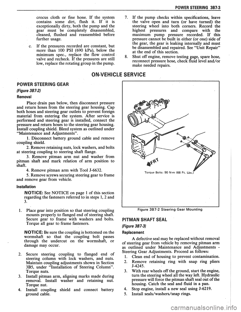
ON-VEHICLE SERVICE
POWER STEERING GEAR
(Figure 387-2)
Removal
Place drain pan below, then disconnect pressure
and return hoses from the steering gear housing. Cap
both hoses and steering gear outlets to prevent foreign
material from entering the system. After service is
performed and steering gear is installed, connect the
pressure and return hoses to the steering gear housing.
Install coupling shield. Bleed system as outlined under
"Maintenance and Adjustments".
1. Disconnect battery ground cable and remove
coupling shield.
2. Remove retaining nuts, lock washers, and bolts
at steering coupling to steering shaft flange.
3. Remove pitman arm nut and washer from
pitman shaft and mark relation of arm position to
shaft.
4. Remove pitman arm with Tool J-6632.
5.
Remove screws securing steering gear to frame
and remove gear from vehicle.
Installation
NOTICE: See NOTICE on page 1 of this section
regarding the fasteners referred to in steps 1,2 and
3.
1. Place gear into position so that steering coupling
mounts properly to flanged end of steering shaft.
Secure gear to frame with washers and bolts.
Torque all gear to frame fasteners.
NOTICE: Be sure the coupling is bottomed on the
wormshaft so that the coupling bolt passes
through the undercut on the wormshaft, or
damage may occur.
2. Secure steering coupling to flanged end of
steering column with lock washers, and nuts.
Maintain coupling adjustments shown in Section
3B5, under "Installation of Steering Column".
Torque nuts.
3. Install pitman arm, aligning marks made during
removal. Install washer and retaining nut.
Torque nut.
4. Install coupling shield and connect battery
ground cable.
Torque Bolts: 90 Nm (66 Ft. ~bs.r
Figure 3B7-2 Steering Gear Mounting
PITMAN SHAFT SEAL
(Figure 387-3)
Replacement
A defective seal may be replaced without removal
of steering gear from vehicle by removing
pitman arm
as outlined under Maintenance and Adjustments
-
Steering Gear Adjustments. Proceed as follows:
1. Clean end of housing to prevent contamination.
2. Remove retaining
ring with snap ring pliers
J-4245.
3. With rear wheels off the ground, start the engine,
turn the steering wheel all the way left. Hydraulic
pressure will force the
pitman shaft seal out of the
housing. Catch the seal and fluid in a pan.
4. Stop engine, install a new seal using 5-6219.
5. Install seals/washers/snap rings.
Page 232 of 1825
TIRES AND WHEELS 3E-1
RES AND WHEELS
NOTICE: All wheel bolt and nut fasteners are important attaching parts in that they could affect the
performance of vital components and systems, and/or could result in major repair expense. They must be replaced
with one of the same part number or with an equivalent part if replacement becomes necessary. Do not use a
replacement part of lesser quality or substitute design. Torque values must be used as specified during reassembly
to assure proper retention of parts.
CONTENTS
Diagnosis ............................................... Section 3 Tire Repair ................................................... 3E-5
General Information .......................... ..... 3E-1 Waddle ........................................................ 3E-5
........ Replacement Tires ....................... ... 3E- 1 Measuring Wheel Runout ............................ 3E-6
P-Metric Tires ...................... .. ................... 3E-2 Spare Tire ...................................................... 3E-6 ................................................ Tire Placard 3E-2 Match Mounting ......................................... 3E-7
.......................................................... Wheels 3E-2 Balancing Tire and Wheel ............................ 3E-7
....................... Maintenance and Adjustments .............. 3E-2 General Balance Precautions 3E-7 ...................................... Wheel Repair .............................................. 3E-2 Off-Car Balancing 3E-8 .............................. Metric Wheel Nuts and Studs .................... .. 3E-3 On-Car Balancing .. ...... 3E-8
......................................... Inflation of Tires ........................................ 3E-3 Wheel Weights 3E-8 .................... Tire Rotation ........................... ...... . 3E-3 Correcting Non-Uniform Tires 3E-8 .......................... Tire Chain Usage ........................................ 3E-4 Aluminum Wheel Cleaning 3E-9 Aluminum Wheel Hub Cap ......................... 3E-9 Service Operations ..................................... 3E-4 Aluminum Wheel Porosity Repair .............. 3E-9 ......................... Wheel Removal .... .......... 3E-4 Aluminum Wheel Refinishing ...................... 3E-9 Tire Mounting and Dismounting ................. 3E-5 Wheel Nut Torque 3E-10 ......................................
GENERAL INFORMATION ~t is recommended that new tires be installed in
pairs on the same axle. If it is necessary to replace only
The tires and are one tire, it should be paired with the tire having the
designed to operate satisfactorily with loads up to and
most tread, to equalize braking traction. including the full rated load capacity when inflated to
Although they may appear different in tread
the recommended inflation pressures.
design, tires built by different manufacturers with
Correct tire pressures, wheel alignment and identical TPC specification numbers, can be
driving techniques have an important influence on tire
intermixed on the same car. life. Heavy cornering, excessive rapid acceleration, and
heavy braking will increase tire wear.
REPLACEMENT TIRES
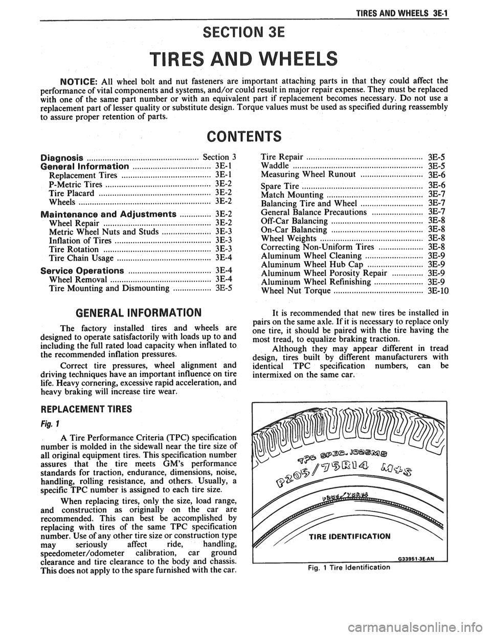
Fig. 1
A Tire Performance Criteria (TPC) specification
number is molded in the sidewall near the tire size of
all original equipment tires. This specification number
assures that the tire meets
GM's performance
standards for traction, endurance, dimensions, noise,
handling, rolling resistance, and others. Usually, a
specific TPC number is assigned to each tire size.
When replacing tires, only the size, load range,
and construction as originally on the car are
recommended. This can best be accomplished by
replacing with tires of the same TPC specification
number. Use of any other tire size or construction type
may seriously affect ride, handling,
speedometer/odometer calibration, car ground
clearance and tire clearance to the body and chassis.
This does not apply to the spare furnished with the car.
v// TIRE IDENTIFICATION
Fig. 1 Tire Identification
Page 233 of 1825
3E.2 TIRES AND WHEELS
P-METRIC SIZED TIRES
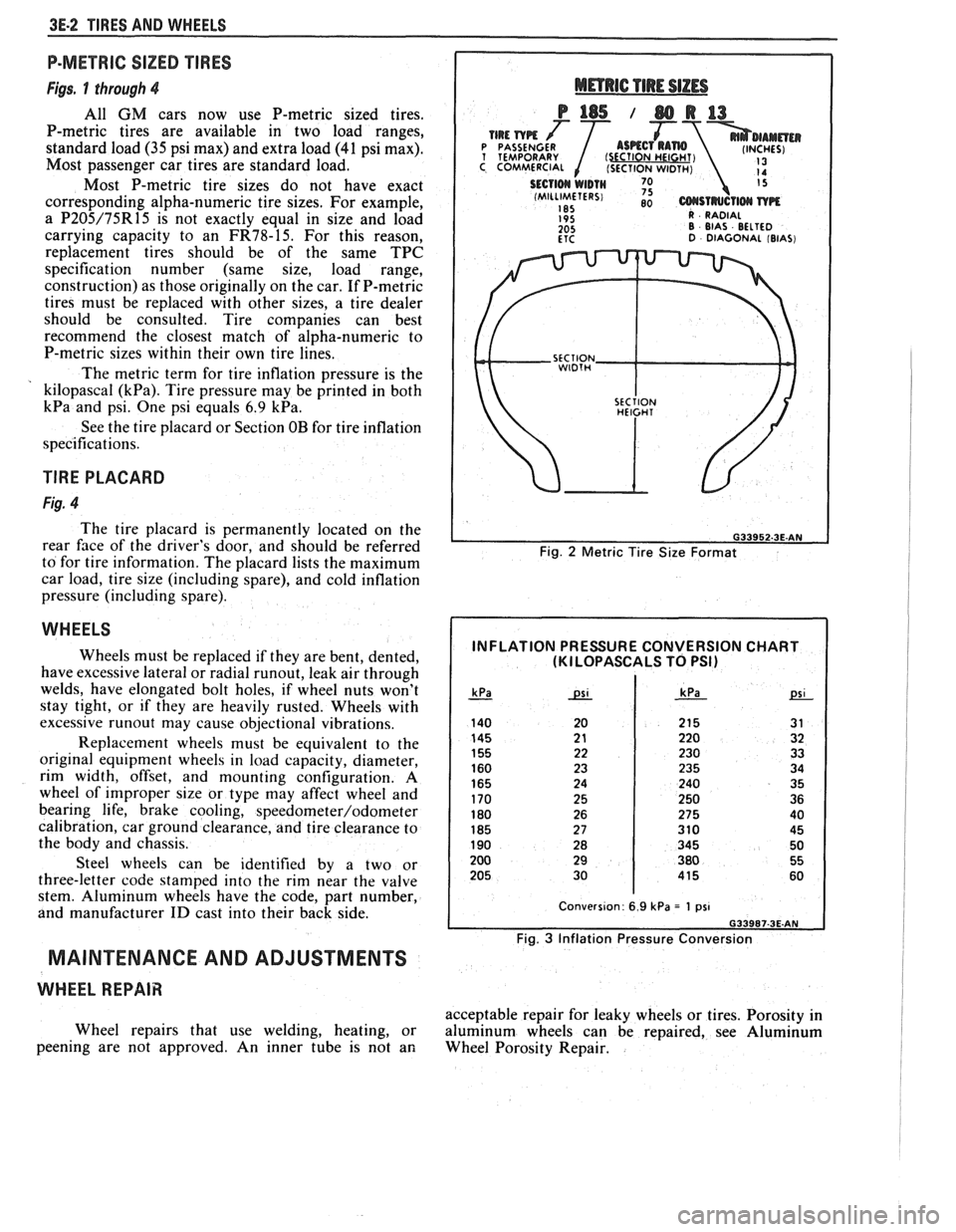
Figs. 1 through 4
All GM cars now use P-metric sized tires.
P-metric tires are available in two load ranges,
standard load
(35 psi max) and extra load (41 psi max).
Most passenger car tires are standard load.
Most P-metric tire sizes do not have exact
corresponding alpha-numeric tire sizes. For example,
a
P205/75R15 is not exactly equal in size and load
carrying capacity to an
FR78-15. For this reason,
replacement tires should be of the same TPC
specification number (same size, load range,
construction) as those originally on the car. If P-metric
tires must be replaced with other sizes, a tire dealer
should be consulted. Tire companies can best
recommend the closest match of alpha-numeric to
P-metric sizes within their own tire lines.
The metric term for tire inflation pressure is the
kilopascal
(kPa). Tire pressure may be printed in both
kPa and psi. One psi equals 6.9 kPa.
See the tire placard or Section OB for tire inflation
specifications.
TlRE PLACARD
Fig. 4
The tire placard is permanently located on the
rear
face of the driver's door, and should be referred
to for tire information. The placard lists the maximum
car load, tire size (including spare), and cold inflation
pressure (including spare).
WHEELS
Wheels must be replaced if they are bent, dented,
have excessive lateral or radial
runout, leak air through
welds, have elongated bolt holes, if wheel nuts won't
stay tight, or if they are heavily rusted. Wheels with
excessive
runout may cause objectional vibrations.
Replacement wheels must be equivalent to the
original equipment wheels in load capacity, diameter,
rim width, offset, and mounting configuration.
A
wheel of improper size or type may affect wheel and
bearing life, brake cooling,
speedometer/odometer
calibration, car ground clearance, and tire clearance to
the body and chassis.
Steel wheels can be identified by a two or
three-letter code stamped into the rim near the valve
stem. Aluminum wheels have the code, part number,
and manufacturer
ID cast into their back side.
MAINTENANCE AND ADJUSTMENTS
WHEEL REPAIR
Wheel repairs that use welding, heating, or
peening are not approved. An inner tube is not an
Fig. 2 Metric Tire Size Format
INFLATION PRESSURE CONVERSION CHART (KI LOPASCALS TO PSI)
Fig. 3 Inflation Pressure Conversion
acceptable repair for leaky wheels or tires. Porosity in
aluminum wheels can be repaired, see Aluminum
Wheel Porosity Repair.
Page 234 of 1825
TIRES AND WHEELS 3E-3
METRIC WHEEL NUTS AND STUDS
Some models use metric wheel nuts and wheel
studs. The nut will have the word "metric" stamped on
its face and the stud will have the letter
"M" stamped
into the threaded end. The word "metric" is stamped
on its head.
The thread size of the metric wheel nuts and
wheel studs are
"MI2 x 1.5". These stand for:
M = Metric
12
= Diameter in millimeters
1.5
= Millimeters per thread
If a broken stud is found, see Section 3C (Front
Suspension) or Section 3D (Rear Suspension) for
replacement procedure.
INFLATION OF TIRES
The pressure recommended for any model is
carefully calculated to give a satisfactory ride,
handling, tread life and load carrying capacity.
Tire pressure, with tires cold, (after car has set for
three hours or more, or driven less than one mile)
should be checked monthly or before any extended trip
and set to the specifications on the tire placard located
on rear face of driver's door. Tire inflation pressure is
also given in Section OB.
Valve caps or extensions should be on the valves
to keep dust and water out.
1. For sustained driving at speeds up to 85
mph (140 km/h), in countries where such
speeds are allowed by law, your tires should be set
at the pressures recommended on your tire
placard.
Sustained driving at speeds
faster than
85 mph (140 km/h), where
permitted
by law, is not advised unless
your car has special high speed tires available
from many tire dealers.
2. Tire pressures may increase as much as 6 psi
when hot.
3. Higher
than recommended pressure can cause:
o Hard ride
o Tire bruising or carcass damage
Rapid tread wear at center of tire
4. Lower
than
recommended pressure can cause:
@ Tire squeal on turns
@ Hard steering
o Rapid and uneven wear on the edges of the
tread
Tire rim bruises and rupture
e Tire cord breakage
o High tire temperatures
o Reduced handling
High fuel consumption
5. Unequal pressure on same axle can cause:
Uneven braking
o Steering lead
o Reduced handling
e Swerve on acceleration
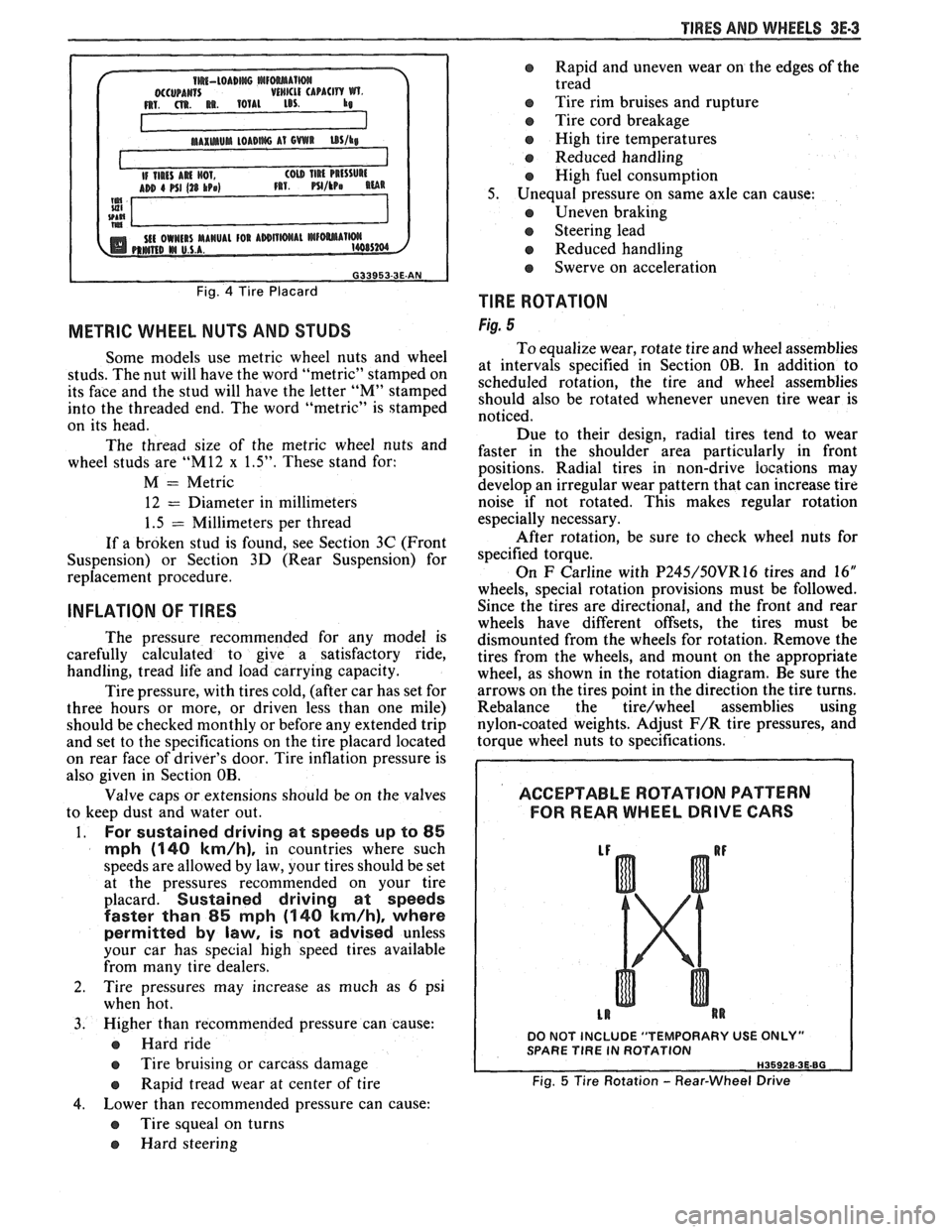
TlRE ROTATION
Fig. 5
To equalize wear, rotate tire and wheel assemblies
at intervals specified in Section OB. In addition to
scheduled rotation, the tire and wheel assemblies
should also be rotated whenever uneven tire wear is
noticed.
Due to their design, radial tires tend to wear
faster in the shoulder area particularly in front
positions. Radial
tires in non-drive
iocations may
develop an irregular wear pattern that can increase tire
noise if not rotated. This makes regular rotation
especially necessary.
After rotation, be sure to check wheel nuts for
specified torque.
On
F Carline with P245/50VR16 tires and 16"
wheels, special rotation provisions must be followed.
Since the tires are directional, and the front and rear
wheels have different offsets, the tires must be
dismounted from the wheels for rotation. Remove the
tires from the wheels, and mount on the appropriate
wheel, as shown in the rotation diagram. Be sure the
arrows on the tires point in the direction the tire turns.
Rebalance the
tire/wheel assemblies using
nylon-coated weights. Adjust
F/R tire pressures, and
torque wheel nuts to specifications.
ACCEPTABLE ROTATION PATTERN
FOR REAR WHEEL
DRIVE GARS
DO NOT INCLUDE "TEMPORARY USE ONLY" SPARE TlRE IN ROTATION
Fig. 5 Tire Rotation - Rear-Wheel Drive