1988 PONTIAC FIERO spare wheel
[x] Cancel search: spare wheelPage 236 of 1825

TIRES AND WI4EELS 3E-5
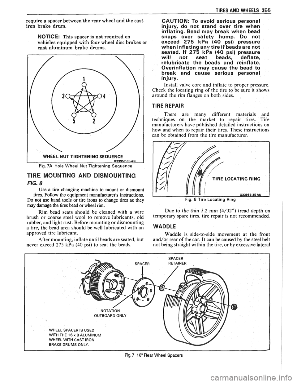
require a spacer between the rear wheel and the cast
iron brake drum.
NOTICE: This spacer is not required on
vehicles equipped with four wheel disc brakes or
cast aluminum brake drums.
Fig. 7A Hole Wheel Nut Tightening Sequence
TlRE MOUNTING AND DISMOUNTING
FIG. 8
Use a tire changing machine to mount or dismount
tires. Follow the equipment manufacturer's instructions.
Do not use hand tools or tire irons to change tires as they
may damage the tires bead or wheel rim.
Rim bead seats should be cleaned with a wire
brush or coarse steel wool to remove lubricants, old
rubber, and light rust. Before mounting or dismounting
a tire, the bead area should be well lubricated with an
approved tire lubricant.
After mounting, inflate until beads are seated, but
never exceed 275
kPa (40 psi) to seat the beads.
CAUTION: To avoid serious personal
injury, do not stand over tire when
inflating. Bead may break when bead
snaps over safety hump. Do not
exceed
275 kPa (40 psi) pressure
when inflating
any tire if beads are not
seated. If
275 kPa (40 psi) pressure
will not seat beads, deflate,
relubricate the beads and reinflate.
Overinflation may cause the bead to
break and cause serious personal
injury.
Install valve core and inflate to proper pressure.
Check the locating ring of the tire to be sure it shows
around the rim flanges on both sides.
TIRE REPAIR
There are many different materials and
techniques on the market to repair tires. Tire
manufacturers have published detailed instructions on
how and when to repair their tires. These instructions
can be obtained from the tire manufacturer.
TlRE LOCATING RING
naaaca a= AM
Fig. 8 Tire Locating Ring
Due to the thin 3.2 mm (4/32") tread depth on
temporary spare tires, tire repair is not recommended.
WADDLE
Waddle is side-to-side movement at the front
and/or rear of the car. It can be caused by the steel belt
not being straight within the tire, or by excessive lateral
WHEEL SPACER IS USED
WITH THE
16 x 8 ALUMINUM
WHEEL WITH CAST IRON
BRAKE DRUMS ONLY.
Fig, 7 16 Rear Wheel Spacers
Page 237 of 1825

3E-6 TIRES AND WHEELS
runout of the tire or wheel. Use a dial indicator on the
tire's sidewall and on the rim's flange to determine if
there is excessive lateral
runout.
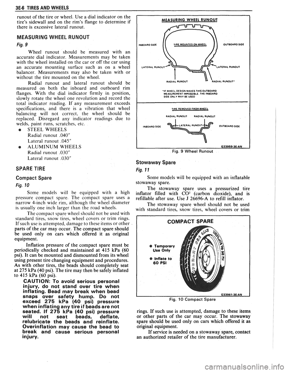
MEASURING WHEEL RUNOUT
Fig. 9
Wheel runout should be measured with an
accurate dial indicator. Measurements may be taken
with the wheel installed on the car or off the car using
an accurate mounting surface such as on a wheel
balancer. Measurements may also be taken with or
without the tire mounted on the wheel.
Radial
runout and lateral runout should be
measured on both the inboard and outboard rim
flanges. With the dial indicator firmly in position,
slowly rotate the wheel one revolution and record the
total indicator reading. If any measurement exceeds
specifications, and there is a vibration that wheel
balancing will not correct, the wheel should be
replaced. Disregard
any indicator readings due to
welds, paint runs, scratches, etc.
e STEEL WHEELS
Radial
runout .040"
Lateral runout .045"
e ALUMINUM WHEELS
Radial
runout .030"
Lateral runout .030"
SPARE TIRE
Compact Spare
Fig. 10
Some models will be equipped with a high
pressure compact spare. The compact spare uses a
narrow 4-inch wide rim, although the wheel diameter
is usually one inch larger than the road wheels.
The compact spare wheel should not be used with
standard tires, snow tires, wheel covers or trim rings.
If such use is attempted, damage to these items or other
parts of the car may occur. The compact spare should
be used only on cars which offered it as original
equipment.
Inflation pressure of the compact spare must be
periodically checked and maintained at
415 kPa (60
psi). It can be mounted and dismounted from its wheel
using present tire changing equipment and procedures.
As with other tires, the beads should completely seat
at
275 kPa (40 psi). The tire may then be safely inflated
to
415 kPa (60 psi).
CAUTION: To avoid serious personal
injury, do not stand over tire when
inflating. Bead may break when bead
snaps over safety hump. Do not
exceed
275 kPa (40 psi) pressure
when inflating any tire
if beads are not
seated. If
275 kPa (40 psi) pressure
will not seat beads, deflate,
relubricate the beads and reinflate.
Overinflation may cause the bead to
break and cause serious personal
injury.
INBOARD SIDE TIRE MOUNTED ON fVHEEL OUTBOARD SIDE
RADIAL
RUNOUT'
'IF WHEEL DESIGN MAKES THISOUTBOARD MEASUREMENT IMPOSSIBLE. THE INBOARD
SIDE ONLY MAY BE USED
I RADIAL RUNOUT RADIAL RUNDUT I
INBOARD SIDE OUTBOARD SIDE
Fig. 9 Wheel Runout
Stowaway Spare
Fig. 11
Some models will be equipped with an inflatable
stowaway spare.
The stowaway spare uses a pressurized tire
inflator filled with
C02 (carbon dioxide), and is
refillable after use. Use
J 26696-A to refill inflator.
The stowaway spare wheel should not be used
with standard tires, snow tires, wheel covers or trim
@ Temporary
Use Only
@ Inflate to 80 PSI
Fig. 10 Compact Spare
rings. If such use is attempted, damage to these items
or other parts of the car may occur. The stowaway
spare should be used only on cars which offered
it as
original equipment.
If service is needed on a stowaway spare, contact
an authorized retailer of the tire manufacturer.
Page 238 of 1825

TIRES AND WHEELS 3E-7
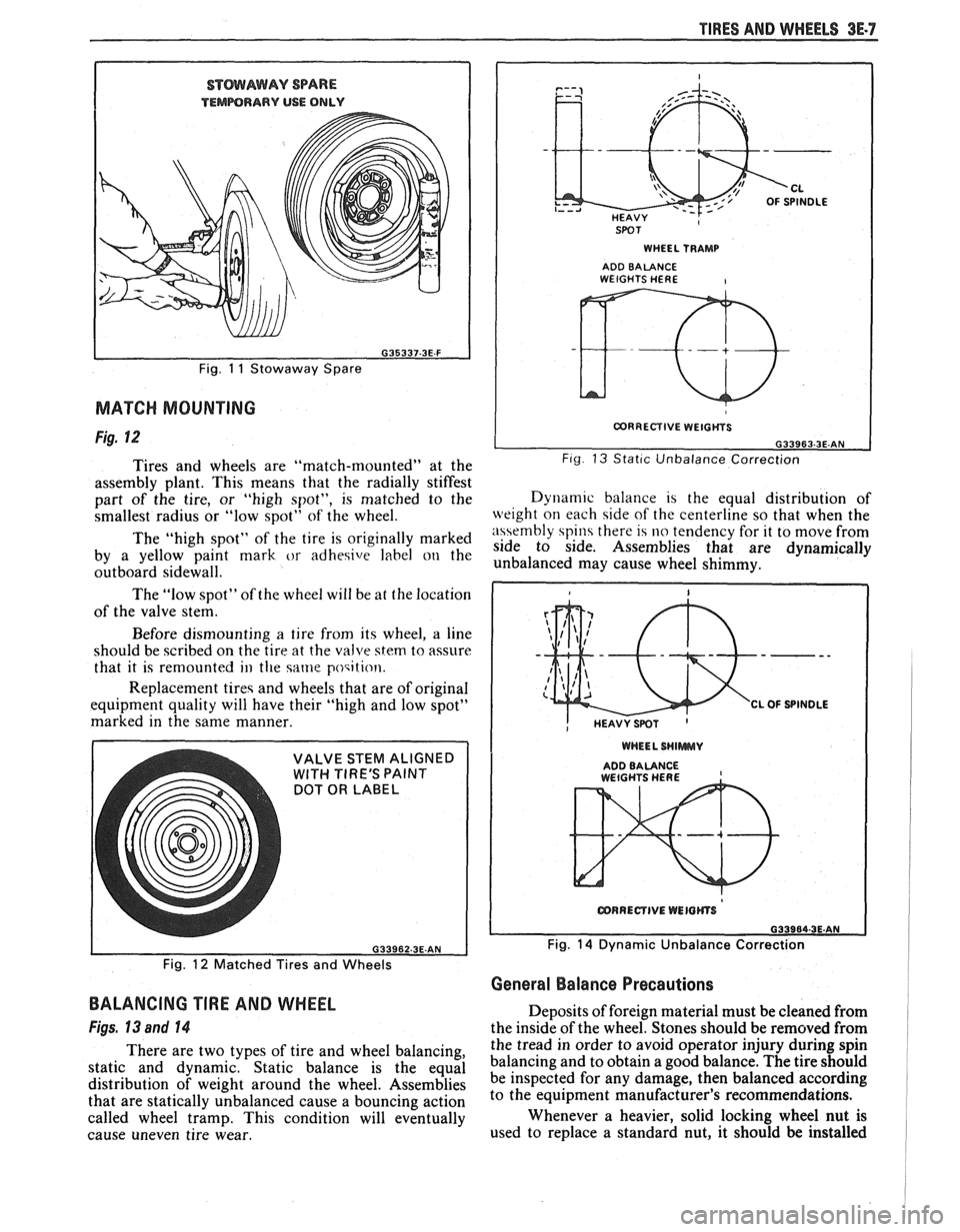
STMAWAY SPARE
TEMPORARY USE ONLV
Fig. 11 Stowaway Spare
MATCH MOUNTING
Fig. 12
Tires and wheels are "match-mounted" at the
assembly plant. This means that the radially stiffest
part of the tire, or "high spot", is matched to the
smallest radius or "low spot" of the wheel.
The "high spot" of the tire is originally marked
by a yellow paint mark
or adhesive label on the
outboard sidewall.
The "low spot" of the wheel will be at the location
of the valve stem.
Before dismounting
a tire from its wheel, a line
should be scribed on the tire at the valve
stem to assure
that it is remounted
ill the same poqition.
Replacement tireq and wheels that are of original
equipment quality will have their "high and low spot"
marked in the same manner.
DOT OR LABEL
SPOT I WHEEL TRAMP I
ADD BALANCE WEIGHTS HERE I
I CORRECTIVE WEIGtiYS I
L G33963-3E.AN Fig 13 Stat~c Unbalance Correction
Dynam~c balance 1s the equal distribution of
weight on each side of the centerline so that when the
n\\embly spin there 14 no tendency for it to move from
side to side. Assemblies that are dynamically
unbalanced may cause wheel shimmy.
WHEEL SHlWWUV
ADDBALANCE , WEtGHTS HERE
Fig. 14 Dynamic Unbalance Correction
Fig.
12 Matched Tires and Wheels
General Balance Precautions
BALANCING TIRE AND WHEEL
Figs, 13 and 14
There are two types of tire and wheel balancing,
static and dynamic. Static balance is the equal
distribution of weight around the wheel. Assemblies
that are statically unbalanced cause a bouncing action
called wheel tramp. This condition will eventually
cause uneven tire wear. Deposits
of foreign material must be cleaned from
the inside of the wheel. Stones should be removed from
the tread in order to avoid operator injury during spin
balancing and to obtain a good balance. The tire should
be inspected for any damage, then balanced according
to the equipment manufacturer's recommendations.
Whenever a heavier, solid locking wheel nut is
used to replace a standard nut, it should
be installed
Page 1823 of 1825

8- CHASSIS INDEX
Recommended Fluids and Lubricants ................ OB-6
Relay Rod
......................................................... 3B6-2
Remote Mirror Control
...... See Body Service Section
5H.1. 15
Repair Procedures
.......................................... 88-50
S
........................................ Scheduled Maintenance OB- 1
Seats (Power) ....................................... Lumbar Support 8A- 145-0
............................. Sequential Fuel Injection 6E3-C2- 1
Service Engine Soon Light
.................................... 8C-3
Sheet Metal and Grille
................................ Section 2C
......................................... General Description .2 C. 1
........................................... Service Procedures .2 C. 1
................................................................. Hood .2 C. 1
...................................................... Hood Hinge 2C-2
Hood Latch and Cable
...................................... 2C-2
Paint
.............................................. Color Matching 2C-5
................................................ Identification -32-6
Interior Plastic Parts ...................................... 2C-6
................................................ Shock Absorbers 3D-
1
Shoe and Lining Assembly
. Brake
............................................ 3000/3 100 Series 5B1-3
3548 Series ...................................................... 5B6-4
Side Marker Lights
.............................................. 8B-2
........ Speakers See 8A- 150-0 & Body
Manual Section
6H- 1
.................... Spark Plug Gap .. .................. 6E3-13-3
................................ Speaker and Speaker Grille 9A-9
Special Tools
............................................ Air Conditioning 1 B-3 5
Air Conditioning Compressor
................................................. Overhaul 1D1-21
........................ Automatic Transaxle AT-700-R4-64
................................................................ Brakes SF-1
Clutch ................................................................ 7C-8
................................................................ Rear 4B1-20
....................................... Rear (Borg Warner) 4B-20
........................... Driveability and Emissions .6 E. 17
................................................ Engine Cooling 6B- 14
Power Steering Pump
& Gear ...................... 3B7-17
............................................... Propeller Shaft .4 A. 12
Steering Wheels and Columns
.......................... 5-35
Specifications Automatic Transmission Unit
............................................ Repair AT-700-R4-59
..................................................... Battery 6D 1-7
................................................................ Brakes 5F-1
Bumpers
......................................................... 2B-5
Charging System
................ .. ................... 6D3-3
.............................................................. Clutch .7 (2.8
....................................... Cranking System 6D2- 1 1
Driveability and Emissions ............................ 6E-23
................................................ Engine (V-6) ..6A 2.26
Engine (V-8) .................................................. 683-28
........................................ Front Suspension 3C- 10
Power Steering Gear and Pump
.................. 3B7-18 ............................................. Propeller Shaft .4 A. 12 ........................................................ Rear Axle 4B-19 ............................ Rear Axle (Borg Warner) 4B 1- 19
Rear Suspension
.............................................. 3D-9
.......................................... Replacement Bulbs 8Br 10 .............................................. Steering Linkage 3B6-6
Steering Wheels and Columns
...................... 3B5-35
........................................ Wheel Alignments 3A-4
....................................................... Speedometer 8C-2
........................................ Speedometer (Removal) 8C-5
...................................................... Speed Sensors 8C-1
Starter ........................................ Section 6D2. 8A-30-0
............................................. Starter (Circuit) 8A-30-0
Steering Linkage ...................................... Section 3B6
....................................... General Description 3B6-1
........................ Maintenance and Adjustments 3B6-1
................................................ On-Car Service 3B6-2
..................................................... Idler Arm 3B6-4
................................................ Pitman Arm 3B6-5
.................................................... Relay Rod 3B6-3
Tie Rods
...................................................... 3B6-2
.................................................. Specifications 3B6-6
Steering, Suspension, Tires and
Wheels Diagnosis
............................................................. 3-1
Steering Wheels and Columns
............................ 3B5-1
..................................... General Information 3B5- 1
Maintenance and Adjustments
...................... 3B5-'
On-Car Service .............................. .. ........... 3B5
Checking for Accident Damage
.................. 3B5-5
Intermediate Shaft ............... .. .................... 3B5-3
Park Lock Cable .......................................... 3B5-4
Standard Column
............................. Automatic Transaxle 3B5-13
Manual Transaxle ................................. 3B5- 19
Tilt Column
.............................. Automatic Transaxle 3B5-27
.................................. Manual Transaxle 3B5-19
Unit Repair Intermediate Shaft
...................................................... Assembly 3B5-6
................................................. Special Tools 3B5-35
Torque Specifications
.................................... 3B5-35
............................................. Starting System 8A-30-0
........................................ Strut Assembly (Front) 3C-4
.................................... ..... Symbols Chart ... 8A-3-0
T
.......................................................... Tachometer 9G-1
Tail/Stop/Turn Signal/Lights .......................... 8B-2
Temperature Cable
.............................................. 112 A-
Temperature Warning Light ................................ 8C-3
Theft Deterrent (Circuit)
.............................. 8A-133-0
Tie Rods
.............................................................. 3B6-2
Tires and Wheels
........................................ Section 3E
Diagnosis
.................................................. Section 3
General Information
......................................... 3E-1
................................................... Metric Tires 3E-2
....................................... Replacement Tires .31 E-
.................................................... Tire Placard 3E-2
........................................................... Wheels 3E-2
Maintenance and Adjustments
.......................... 3E-2
.......................... Aluminum Wheel Cleaning 3E-9
............................. ......... Inflation of Tires .. 3E-3
........................................ Tire Chain Usage 3E-4
.................................................. Tire Rotation 3E-3
.............................................. Wheel Repair 3E-2
...................................... Wheel Studs/Nuts 3E-3
........................................... Service Operations 3E-4
........................ Aluminum Wheel Cleaning 3E-9
.................................... Balance Precautions 3E-7
............................ Balancing Tire and Wheel 3E-7
.............................................. Compact Spare 3E-6
........................ Correcting Nonuniform Tires 3E-8