1988 PONTIAC FIERO heating
[x] Cancel search: heatingPage 1698 of 1825
STATIONARY GLASS - F STYLE 2H.1
ONARY GLASS
Removal of Minor Scratches and
Abrasions
........................... .. ................... 2H- 1
Windshield Reveal Molding ............................ 2H-2
Stationary Glass ............................................... 2H-2
Adhesive Service Kit .................................. 2H-2
Window Removal ....................................... 2H-3
......................... Installation - Short Method 2H-3
.................. Installation - Extended Method 2H-4
................................... Waterleak Correction 2H-5
.................. Bonded Rearview Mirror Support 2H-5
.................................. Rear Window Defogger 2H-6
REMOVAL OF MINOR SCRATCHES AND
ABRASIONS
Minor glass scratches and abrasions on the
outside surface of the glass can be removed or reduced
by using the methods described in this section.
There are two basic types of auto glass: laminated
safety plate (used in all windshields) and solid
tempered safety plate (used in side and back windows).
A major concern in glass polishing is the chance
of causing double vision in areas of occupant vision.
For this reason, removal of scratches or abrasions on
a windshield in the occupant's line of vision is more
limited than in other areas. Distortion is most apt to
result when trying to remove deep scratches. Scratch
removal must be performed with care.
Tools Required:
e Low speed (600- 1300 RPM) rotary polisher (Ski1
Model No. 570 or equivalent).
Wool felt rotary-type polishing pad, about 75 mm
(3") in diameter and 50 mm (2") thick.
e Powdered cerium oxide (No. 14 Rareox or
equivalent) mixed with water as the abrasive
compound. Follow manufacturer's directions
when using any type of polishing compound.
e Wide mouth container to hold the polish.
NOTICE: Glass polishing must not be performed
on inside surface of rear window glass which has
heating elements in the glass because the heating
elements will be damaged.
1. Mix two parts of polishing compound (No. 14
Rareox or equivalent) with one part water to
obtain a creamy mixture.
2. Stir mixture now and then to maintain a creamy
texture. Powdered cerium oxide is hard to mix
with water and tends to separate.
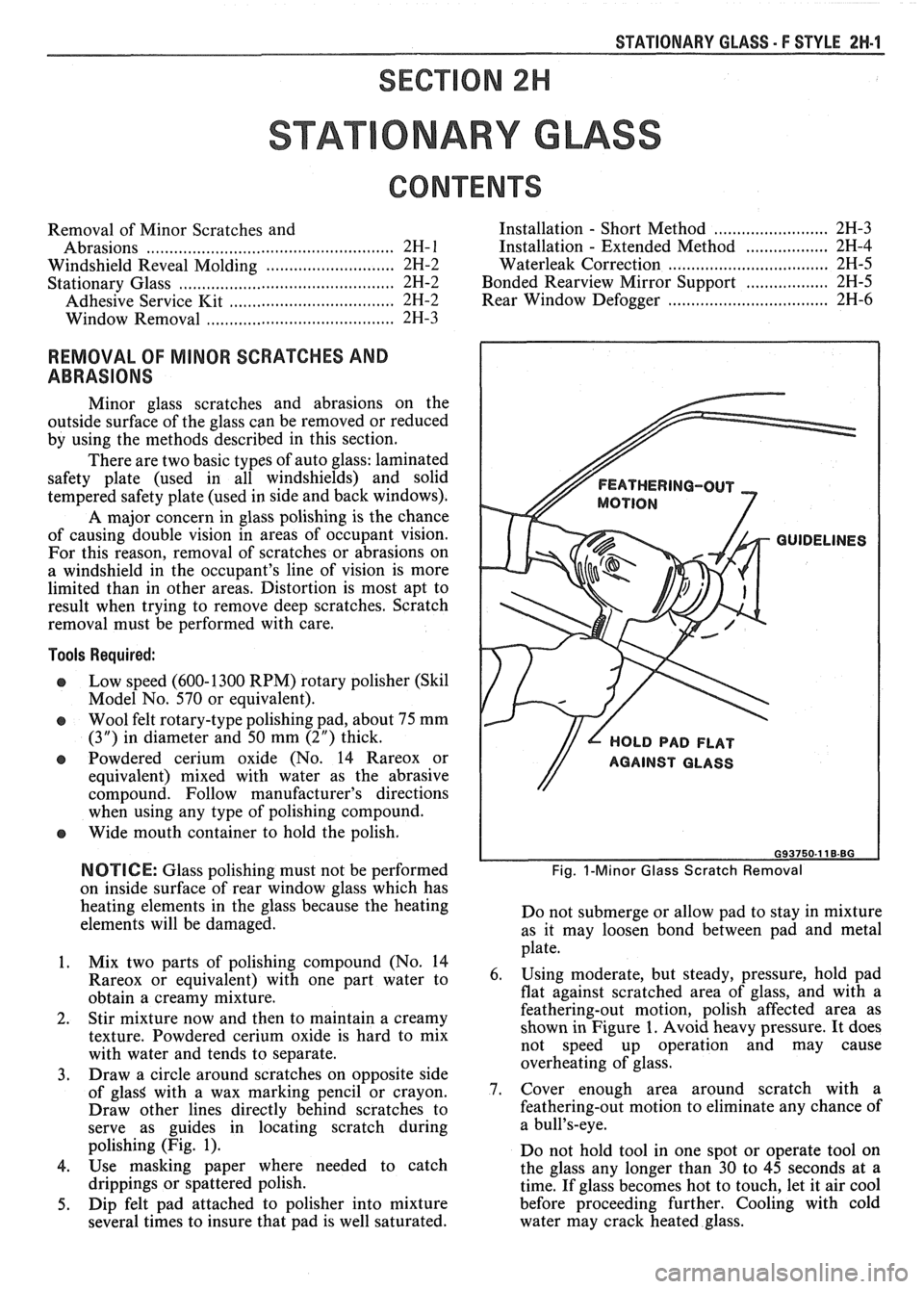
3. Draw a circle around scratches on opposite side
of
glasS with a wax marking pencil or crayon.
Draw other lines directly behind scratches to
serve as guides in locating scratch during
polishing (Fig. 1).
4. Use masking paper where needed to catch
drippings or spattered polish.
5. Dip felt pad attached to polisher into mixture
several times to insure that pad is well saturated.
FEATHERING-OUT
MOTION
GUIDELINES
// L HOLD PAD FLAT
Fig. I-Minor Glass Scratch Removal
Do not submerge or allow pad to stay in mixture
as it may loosen bond between pad and metal
plate.
6. Using moderate, but steady, pressure, hold pad
flat against scratched area of glass, and with a
feathering-out motion, polish affected area as
shown in Figure 1. Avoid heavy pressure. It does
not speed up operation and may cause
overheating of glass.
7. Cover enough area around scratch with a
feathering-out motion to eliminate any chance of
a bull's-eye.
Do not hold tool in one spot or operate tool on
the glass any longer than 30 to 45 seconds at a
time. If glass becomes hot to touch, let it air cool
before proceeding further. Cooling with cold
water may crack heated glass.
Page 1770 of 1825
ROOF - F STYLE 8H-11
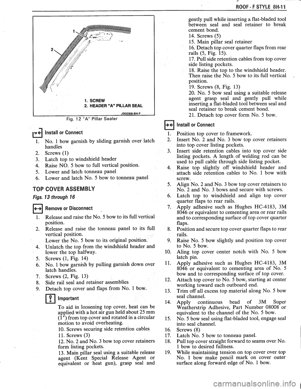
1. SCREW
2. HEADER "Ar' PILLAR SEAL
Fig. 12 "A" Pillar Sealer
gently pull while inserting a flat-bladed tool
between seal and seal retainer to break
cement bond.
14. Screws (5)
15. Main pillar seal retainer
16. Detach top cover quarter flaps from rear
rails (5, Fig. 15).
17. Pull side retention cables from top cover
side listing pockets.
18. Raise the top to the windshield header.
Then raise the No. 5 bow to its full vertical
position.
19. Screws (8, Fig. 13)
20. No. 5 bow seal using a suitable release
agent grasp seal and gently pull while
inserting a flat-bladed tool between seal and
seal retainer to break cement bond.
21. Detach top cover form No. 5 bow.
Install or Connect
lnstall or connect 1. Position top cover to framework.
1. No.
1 bow garnish by sliding garnish over latch
2. Insert No. 2 and No. 3 bow top cover retainers
handles into
top cover listing pockets.
2. Screws (1) 3. Insert side retention cables into top cover side
3. Latch
top to windshield header listing pockets.
A length of welding rod can be
used to pull cable through side listing pocket.
4. Raise
NO. 5 bow to full vertical position.
4. Raise top slightly off windshield header and
5. Lower
and latch tonneau panel
attach side retention cables to No. 1 bow with
6. Lower
and latch No. 5 bow to tonneau panel
screw.
TOP COVER ASSEMBLY
Figs. 13 through 16 6. 5.
Align
No. 2 and No. 3 bow top cover retainers to
No. 2 and No. 3 bows and secure with screws.
Remove or Disconnect 7.
1. Release
and raise the No. 5 bow to its full vertical
position.
2. Release and raise the tonneau panel to its full 8,
vertical position.
Lower the No. 5 bow to its original position. 9.
4. Unlatch the top
from the windshield header and
lower the top halfway.
10.
Screws (1, Fig. 14)
No. 1 bow garnish by pulling garnish down over
latch handles.
Screws (2, Fig. 13)
Side rail seal and retainer assemblies
Detach top cover and flaps from No. 1 bow.
Important
To aid in loosening top cover, heat can be
applied with a hot air gun held about 25 mm
(1 ") from top cover and rotated in a circular
motion to avoid overheating.
10. Screws securing side retention cables
1 1. Screws (3)
12. No. 2 and No. 3 bow top cover retainers
form listing pockets.
13. Main pillar seal using a suitable release
agent (Kent Special Release Agent or
equivalent or heat gun), grasp seal and Latch
top to windshield and align top cover
quarter flaps to rear rails.
Apply adhesive such as Hughes HC-4183, 3M
8046 or equivalent to cementing area or rear rails
and to corresponding surface of top cover quarter
flaps.
Position and secure top cover quarter flaps to rear
rails.
Raise No. 5 bow slightly and position top cover
to No. 5 bow.
Aling top cover center notch with No. 5 bow
--. latch pin.
Apply adhesive such as Hughes HC-4183, 3M
8046 or equivalent to cementing area of No. 5
bow and to corresponding surface of top cover.
Attach top cover to No. 5 bow, starting at center
working toward each outboard end.
Trim off all excess top material along No. 5 bow
- seal channel.
14. Apply continuous bead of 3M Super
Weatherstrip Adhesive, Part Number 08008 or
equivalent to the channel of the No. 5 bow.
15. No. 5 bow seal using flat-bladed tool, engage seal
into seal channel.
16. Screws (8)
17. Latch No. 5 bow to tonneau panel.
18. Pull top cover straight forward to seams over No.
1 bow to desired fullness.
19. While maintaining tension on top cover over top
No. 1 bow make pencil mark on cover outer
surface along forward edge of No. 1 bow.
Page 1773 of 1825
8H-14 ROOF - F STYLE
(1 ") from top cover and rotated in a circu,
motion to avoid overheating.
15. Screw securing side retention cables.
16. Side stay pads from No. 1 bow. Using a 3.2 mm
(1/8") drill bit, drill out rivets.
17. Side stay pads from No. 2 bow. Note location and
spacing of staples before removal.
18. Bolts (6, Fig. 17)
19. Bolts (5)
20. No. 1 and No. 2 bow assembly
Install or Connect
1.
No. 1 and No. 2 bow assembly
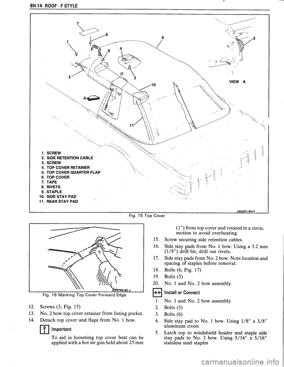
12. Screws (3, Fig. 15)
2. Bolts (5)
13. No. 2 bow top cover retainer from listing pocket. 3.
~olts (6) . .
14. Detach top
cover and flaps from No. 1 bow.
4. Side stay pad to No. 1 bow. Using 1/8" x 3/8"
aluminum rivets Important 5. Latch top to windshield header and staple side
To aid in loosening top cover heat can be
stay pads to No. 2 bow. Using 5/16"
x 5/16"
applied with a hot air gun held about 25 mm
stainless steel staples
Page 1774 of 1825
WOOF - F STYLE 8H-16
Lower top halfway and fold top cover back over
No. 1 bow. Secure side retention cables to No. 1
bow with screw
Top cover retainer into listing pocket and align
top cover retainer to No. 2 bow.
Screws (3)
Apply adhesive such as Hughes HC-4183, 3M
8046 or equivalent to cementing area of No. 1
bow and to corresponding surface of top cover
and flaps.
Align and attach flaps and top cover to No. 1
bow.
Side rail seal and retainer assemblies with screws
No. 1 bow garnish by sliding garnish over latch
handles.
Screws (1)
Latch the top to the windshield header
Raise No, 5 bow to full vertical position.
Lower and latch tonneau panel
Lower No. 5 bow and engage the pin into the
latching hole on the tonneau panel.
Secure the No. 5 bow to tonneau by pulling the
release lever, located on the side of the tonneau
panel.
NO. 3 BOW
Figs. 15 and 17
Remove or Disconnect
Unlatch No. 5 bow and raise it to full vertical
position.
Screws retaining No. 3 bow top cover retainer.
Screws retaining rear stay pad brackets to No. 5
bow.
Pull No.
4 bow rearward and fold top cover
forward over the No. 3 bow.
Mark location of No. 3 bow (forward and
rearward edges) on the side stay pads, using a
sharpened grease pencil.
Side stay pads from No. 3 bow. Note location and
spacing of staples before removal.
Screws (8, Fig. 17)
No. 3 bow
Install or Connect
1. No. 3 bow
2. Screws (7, Fig. 17)
3. Side stay pads to No. 3 bow according to
reference marks. Using 5/16"
x 5/16" stainless
steel staples.
4. Rear stay pad and brackets to No. 5 bow with
screws
5. Fold top cover rearward back over No. 3 bow and
align top cover retainer and listing pocket with
No. 3 bow.
6. Screws (3, Fig. 15)
7. Lower No. 5 bow and latch it to the tonneau
panel.
N0.4 BOW
Fig. 17
Remove or Disconnect
1.
Unlatch No. 5 bow and raise it to full vertical
position.
2. River using 3.2 mm
(1/8") drill bit.
3. Screws (1 1)
4. No.
4 bow by sliding rear and side stay pads off
the No. 4 bow.
a Install or Connect
1.
No. 4 bow by sliding rear and side stay pads onto
the No. 4 bow.
2. Screws
(11)
3.
Rivets using 1/8" x 3/16" aluminum rivets.
4. Lower No.
5 bow and latch it to the tonneau
panel.
NO. 5 BOW
Fig. 13
Remove or Disconnect
1.
Main pillar seal and retainer (see procedure).
2. Screws attaching seal to rear rail
3. Unlatch No. 5 bow and raise it to full vertical
position.
4. No.
5 bow seal using a flat-bladed tool (such as
5-21 104 or equivalent, a suitable release agent or
heat gun will aid in breaking the seal adhesive
bond. Carefully pull on seal while inserting tool
between seal and retainer to break adhesive bond.
5. Detach top cover form No. 5 bow.
Important
To aid in loosening top cover heat can be
applied with a hot air gun held about 25
mrn
(1 ") from top cover and rotated in a circular
motion to avoid overheating.
6. Screws and rear stay pad bracket
7. Screws and No. 4 bow
8. Screws (1 3)
9. No. 5 bow
Install or Connect
No. 5 bow
Screws (13)
Inspect to make sure No. 5 bow latching pin
is
properly aligned to latching lock on tonneau
panel.
Adjust No. 5 bow to tonneau cover as required.
Screws (13)
No. 4 bow
Screws (1
1)
Rear stay pad brackets with rear stay pads
Screws (16)
Raise and position rear edge of top cover to
No.
5 bow.
Page 1818 of 1825
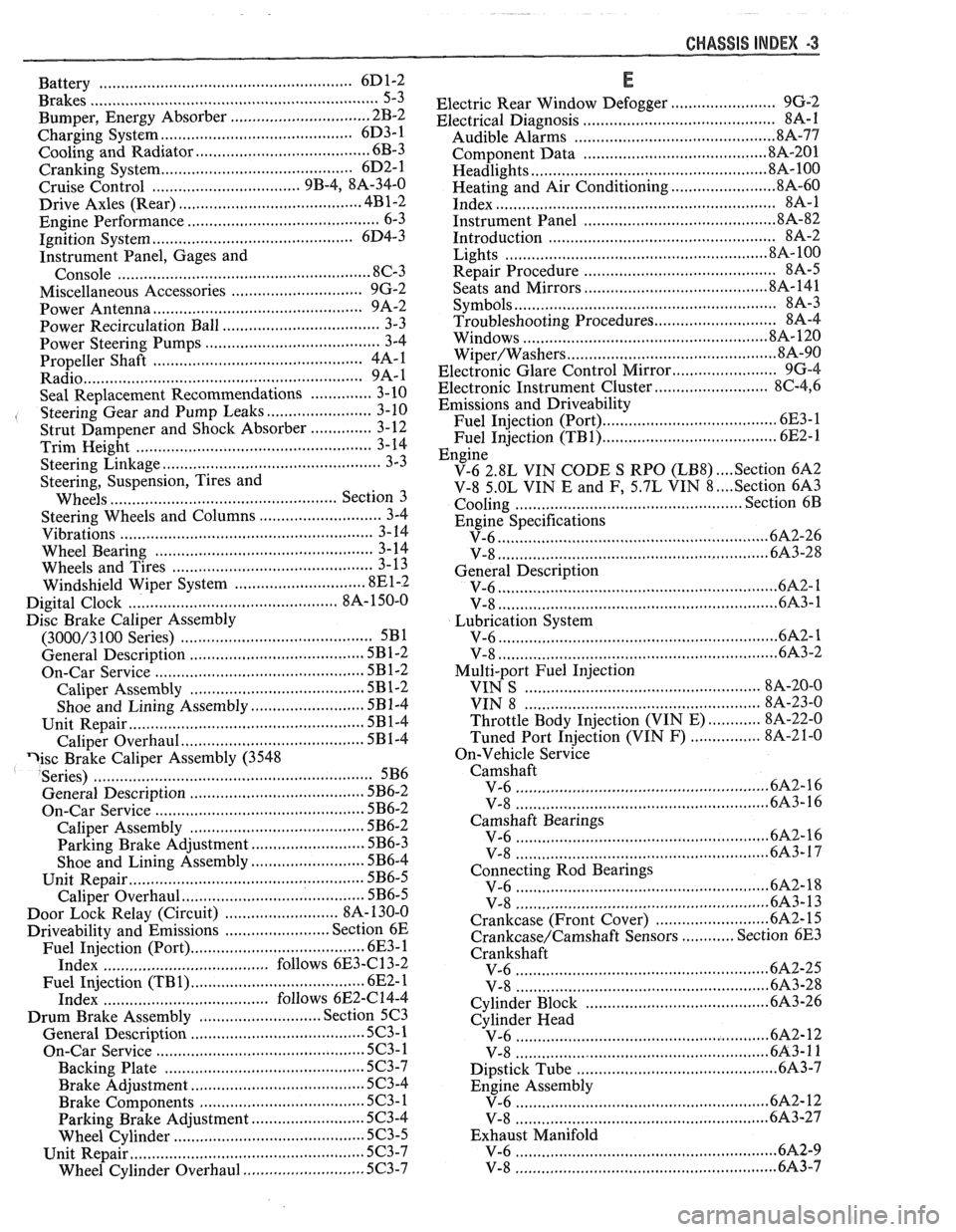
Battery .......................................................... 6D1-2
Brakes
.................................................................. 5-3
................................ Bumper. Energy Absorber 2B-2
........................................... Charging System 6D3- 1
........................................ Cooling and Radiator 6B-3
....................... ................ Cranking System .. 6D2- 1
Cruise Control
................................. 9B-4, 8A-34-0
......................................... Drive Axles (Rear) 4B1-2
Engine Performance
......................................... 6-3
.............................................. Ignition System 6D4-3
Instrument Panel, Gages and
.................................................... Console 8C-3
............................. Miscellaneous Accessories 9G-2
............................................... Power Antenna 9A-2
Power Recirculation Ball
.................................. 3-3
Power Steering Pumps
........................................ 3-4
.............................................. Propeller Shaft 4A- 1
................................................................ Radio 9A-1
.............. Seal Replacement Recommendations 3- 10
........................ . Steering Gear and Pump Leaks 3-10
.............. Strut Dampener and Shock Absorber 3- 12
.................................................... Trim
Height 3- 14
.................................................. Steering Linkage 3-3
Steering, Suspension, Tires and
Wheels
.............................. .. ................. Section 3
Steering Wheels and Columns
............................ 3-4 ......................................................... Vibrations 3- 14
................................................. Wheel Bearing 3-14 .............................................. Wheels and Tires 3- 13
........................... Windshield Wiper System 8El-2
............................................. Digital Cloclc 8A- 150-0
Disc Brake Caliper Assembly
.......................................... (3000/3 100 Series) 5B1
............... ................... General Description .. 5B 1-2 ............................................... On-Car Service 5B 1-2
...................................... Caliper Assembly 5B 1-2
.......................... Shoe and Lining Assembly 5B 1-4
...................................................... Unit Repair
5B 1-4
.......................................... Caliper Overhaul 5B 1-4
?isc Brake Caliper Assembly (3548
Series)
............................................................. 5B6
General Description
....................................... 5B6-2
On-Car Service
............................................... 5B6-2
....................................... Caliper Assembly 5B6-2
.......................... Parking Brake Adjustment 5B6-3
.......................... Shoe and Lining Assembly 5B6-4
Unit Repair
............................... ... .................... 5B6-5
Caliper Overhaul
.......................................... 5B6-5
.......................... Door Lock Relay (Circuit) 8A- 130-0
Driveability and Emissions
........................ Section 6E
Fuel Injection (Port)
..................................... 6E3-1
Index
................................... follows 6E3-(213-2
...................................... Fuel Injection (TB 1) .6E
2- 1
...................................... Index follows 6E2-C 14-4
Drum Brake Assembly
................... ......... Section 5C3
General Description
......................... ... ............ 5C3-1
........................................... On-Car Service 5C3- 1
Backing Plate
........................................ 5C3-7
....................................... Brake Adjustment .5C 3-4
..................................... Brake Components 5C3-1
Parking Brake Adjustment
.......................... 5C3-4
Wheel Cylinder ........................................... 5C3-5 ..................................................... Unit Repair 5C3-7
............................ Wheel Cylinder Overhaul 5C3-7
CHASSIS INDEX m3
E
........................ Electric Rear Window Defogger 9G-2 ............................................ Electrical Diagnosis 88-1
Audible Alarms .............................................. 81%-77
.......................................... Component Data 818-201
.................................................... Headlights 8A- 100
........................ Heating and Air Conditioning 8A-60 .............................................................. Index $A- 1
........................................... Instrument Panel .8 A-82
.................................................. Introduction 8A-2
........................................................... Lights .8 A- 100
............................................ Repair Procedure 88-5 ........................................ Seats and Mirrors 8A- 141
......................................................... Symbols 8A-3
Troubleshooting Procedures ............................ 8A-4
.................................................. ... Windows .. .8 A- 120
............................................... Wiper/Washers .8 A-90
Electronic Glare Control Mirror
........................ 9G-4
.......................... Electronic Instrument Cluster 86-4, 6
Emissions and Driveability
....................................... Fuel Injection (Port) 6E3- 1
....................................... Fuel Injection (TB1) 6E2-1
Engine
.... V-6 2.8L VIN CODE S RPO (LB8) Section 6A2
.... V-8 5.OL VIN E and F, 5.7L VIN 8 Section 6A3
................................................. Cooling Section 6B
Engine Specifications
............................................................ V-6 6A2-26
............................................................. V-8 683-28
General Description
.............................................................. V-6 61 ............................................................. V-8 6A3-1
Lubrication System ........................................................... V-6 ..6A 2- 1
................................................................ V-8 6A3-2
Multi-port Fuel Injection
..................................................... VIN S 8A-20-0
................................................. VIN 8 8A-23-0
............ Throttle Body Injection (VIN E) 8A-22-0
................ Tuned Port Injection (VIN F) 8A-2 1-0
On-Vehicle Service Camshaft
......................................................... V-6 6A2-16
................................ ..................... V-8 .. 6A3-16
Camshaft Bearings
......................................................... V-6 6A2-16
...................................................... V-8 ..6A 3-17
Connecting Rod Bearings
......................................................... V-6 .6A 2- 18
................................................... V-8 6A3-13
...................... Crankcase (Front Cover) .6A
2- 15
............ Crankcase/Camshaft Sensors Section 6E3
Crankshaft
....................................................... V-6 6A2-25
......................................................... V-8 .6A 3-28
......................................... Cylinder Block .6A 3-26
Cylinder Head
.......................................................... V-6 682-12
.......................................................... V-8 6A3-11
Dipstick Tube .............................................. 6A3-7
Engine Assembly
....................................................... V-6 6212
.......................................................... V-8 6A3-27
Exhaust Manifold
........................................................ V-6 .6A 2-9
V-8
....................................................... 6A3-7