1988 PONTIAC FIERO catalytic converter
[x] Cancel search: catalytic converterPage 5 of 1825
OA-2 GENERAL INFORMATION
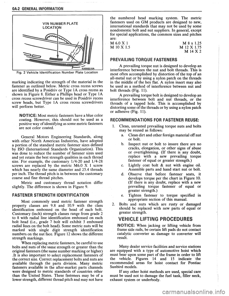
VIN NUMBER PLATE
LOCATION
Fig. 2 Vehicle Identification Number Plate Location
marking indicating the strength of the material in the
fastener as outlined below. Metric cross recess screws
are identified by a Posidriv or Type
1A cross recess as
shown in Figure 8. Either a Phillips head or Type
1A
cross recess screwdriver can be used in Posidriv recess
screw heads, but Type
1A cross recess screwdrivers
will perform better.
NOTICE: Most metric fasteners have a blue color
coating. However, this should not be used as a
positive way of identifying as some metric fasteners
are not color coated.
General Motors Engineering Standards, along
with other North American Industries, have adopted
a portion of the standard metric fastener sizes defined
by
IS0 (International Standards Organization). This
was done to reduce the number of fastener sizes used
and yet retain the best strength qualities in each thread
size. For example, the customary 1/4-20 and 1/4-28
screws are replaced by the metric
M6.0 X 1 screw
which has nearly the same diameter and
25.4 threads
per inch. The thread pitch is in between the customary
coarse and fine thread pitches.
Metric and customary thread notation differ
slightly. The difference is shown in Figure 9.
FASTENER STRENGTH ODENTIFIGATION
Most commonly used metric fastener strength
property classes are 9.8 and 10.9 with the class
identification embossed on the head of each bolt.
Customary (inch) strength classes range from grade 2
to 8 with radial line identification embossed on each
bolt head
(i.e., grade 7 bolt will exhibit 5 embossed
radial lines on the bolt head). Some metric nuts will be
marked with single digit strength identification
numbers on the nut face. Figure 12 shows the different
strength markings.
When replacing metric fasteners, be careful to use
bolts and nuts of the same strength or greater than the
original fasteners (the same number marking or higher)
.It is also important to select replacement fasteners of
the correct size. Correct replacement bolts and nuts are
available through the parts division. Many metric
fasteners available in the after-market parts channels
were designed to metric standards of countries other
than the United States. These fasteners may be of a
lower strength, different thread pitch and may not have the
numbered head marking system. The metric
fasteners used on GM products are designed to new,
international standards that may not be used by some
nondomestic bolt and nut suppliers. In general, except
for special applications, the common sizes and pitches
are:
M 6.0
X 1
M 8 x 1.25
M 10 X 1.5 M 12 X 1.75
M 14x2 I
PREVAILING TORQUE FASTENERS
A prevailing torque nut is designed to develop an
interference between the nut and bolt threads. This is
most often accomplished by distortion of the top of an
all-metal nut or by using a nylon patch on the threads
in the middle of the hex flat.
A nylon insert may also
be used as a method of interference between nut and
bolt threads (Fig. 11).
A prevailing torque bolt is designed to develop an
interference between bolt and nut threads, or the
threads of a tapped hole. This is accomplished by
distorting some of the threads or by using a nylon patch
or adhesive (Fig. 11).
RECOMMENDATIONS FOR FASTENER REUSE: I
Clean, unrusted prevailing torque nuts and bolts
may be reused as follows:
a. Clean dirt and other foreign material off nut
or bolt.
b. Inspect nut or bolt to insure there are no
cracks, elongation, or other signs of abuse
or overtightening. (If there is any doubt,
replace with a new prevailing torque
fastener of equal or greater strength.)
c. Lightly coat bolt
& nut with engine oil.
Assemble parts and hand start nut or bolt.
d. Observe that before fastener seats, it
develops torque per the chart in Figure
10.
(If there is any doubt, replace with a new
prevailing torque fastener of equal or
greater strength.)
e. Tighten fastener to torque specified in
appropriate section of this manual.
Bolts and nuts which are rusty or damaged
should be replaced with new parts of equal or
greater strength.
VEHICLE LIF"TING PROCEDURES
NOTICE: When jacking or lifting vehicle from
frame side rails, be certain lift pads do not contact
catalytic converter as damage to converter will
result.
Many dealer service facilities and service stations
are equipped with a type of automotive hoist which
must bear upon some part of the frame in order to lift
the vehicle. Figures 14 and 15 indicate the
recommended areas for hoist contact for Pontiac
Sunbird models.
If any other hoist methods are used, special care
must be used not to damage the fuel tank, filler neck,
I
exhaust system or underbody. I
Page 16 of 1825

- -
GENERAL INFORMATION OA-13
LIST OF AUTOMOTIVE ABBREVIATIONS
WHICH MAY
BE USED IN THIS MANUAL
A-6 - Axial 6 Cyl. A C Compressor AIC - Air Conditioning
ACC - Auto'matic Climate Control
EMF
- Electromotive Force PAIR - Pulse Air Injection Reaction System
EMR - Electronic Module Retard
P B - Power Brakes
EOS - Exhaust Oxygen Sensor
PCV - Positive Crankcase Ventilation
ESC - Electronic Spark Control
PECV - Power Enrichment Control Valve
APT
- Adjustable Part Throttle
AT - Automatic Transmission
ATC - Automatic Temperature Control
ATDC
- After Top Dead Center
FMVSS
- Federal Motor Vehicle Safety BAR0 - Barometric Absolute Pressure Sensor
Ft. Lb. - Foot Pounds (Torque)
Bat. + - Positive Terminal FWD - Front Wheel Drive
- Four Wheel Drive
BHP - Brake Horsepower 4 x 4 - Four Wheel Drive
BP - Back Pressure
BTDC - Before Top Dead Center
HD - Heavy Duty HE1 - High Energy Ignition
Cat. Conv. - Catalytic Converter
CC - Catalytic Converter
- Cubic Centimeter - Converter Clutch
CCC - Computer Command Control
HVM
- Heater-Vent-Module
IAC
- ldle Air Control CCOT - Cycling Clutch (Orifice) Tube IC - Integrated Circuit CCP - Controlled Canister Purge
ID - Identification
C.E. - Check Engine - Inside Diameter
CEAB - Cold Engine Airbleed ILC - Idle Load Compensator
CEMF - Counter Electromotive Force I/P - Instrument Panel
CID - Cubic Inch Displacement ISC - Idle Speed Control CLOOp - Closed Loop
CLCC - Closed Loop Carburetor Control km - Kilometers
CP
- Canister Purge kmiL - Kilometers Liter (mpg) Cu. In. - Cubic Inch kPa - Kilopascals
CV - Constant Velocity
Cyl.
- Cylinder(s)
L-4 - Four Cylinder In-Line (Engine)
DBB - Dual Bed Bead L-6 - Six Cylinder In-Line (Engine)
DBM - Dual Bed Monolith
LF - Left Front DEFl - Digital Electronic Fuel Injection LR - Left Rear DFI - Digital Fuel Injection
Diff. - Differential Man. Vac. - Manifold Vacuum Distr. - Distributor MAP - Manifold Absolute Pressure
EAC
- Electric Air Control Valve
EAS - Electric Air Switching Valve MPG - Miles Per Gallon
ECC - Electronic Comfort Control
MPH - Miles Per Hour
ECM - Electronic Control Module MT - Manual Transmission
N.m - Newton Metres (Torque)
Emission Control
Fig. 014-15 -- Common Abbreviations
Page 20 of 1825
F CARLINE
ITEM 10
TransmissionRransaxle Service
The manual transmission or transaxle fluid does not
require changing. (Corvette only.) Change fluid in over-
drive unit every 30,000 miles (50 000 km).
For automatic transmissions or transaxles, change
both the fluid and filter every 15,000 miles (25 000 km) if
the car is mainly driven under one or more of these
conditions:
@ In heavy city traffic where the outside temperature
regularly reaches 90°F (32°C) or higher.
@ In hilly or mountainous terrain.
@ Frequent trailer pulling.
@ Uses such as found in taxi, police car or delivery
service.
If you do not use your car under any of these condi-
tions, change both the fluid and filter every 100,000 miles
(160 000 km). See you Owner's Manual for further
details.
ITEM 11
Spark Plug Service*
Replace spark plugs with type listed in your Owner's
Manual.
ITEM 12
Spark Plug Wire Inspection*
Clean wires and inspect for burns, cracks or other dam-
age. Check the wire boot fit at distributor and at spark plugs.
Replace wires as needed.
ITEM 13
Positive Crankcase Ventilation (PCV) Valve
Inspection*
Inspect valve for proper function. Replace valve if
necessary as well as any worn, plugged or collapsed
hoses.
ITEM 14
EGR System Service*
Conduct EGR System Service as referenced in the
EGR System Chart shown in the appropriate 6E Section.
Also, refer to your GM maintenance schedule booklet for
specific applications.
ITEM 15
Air Cleaner and PCV Filter Replacement*
On 1.6 and 2.0 liter engines, replace every 50,000
miles (80 000 km). On all other engines, replace every
30,000 miles (50 000 km). Replace more often under
dusty conditions. Ask your dealer for the proper replace-
ment interval for your driving conditions.
MAINTENANCE AND LUBRICATION 08-3
ITEM 16
Engine Timing Check*
Adjust timing to underhood label specifications. If
no specifications are shown, no adjustment is needed.
ITEM 17
Fuel Tank, Cap and Lines Inspection*
Inspect fuel tank, cap and lines (including fuel rails
and injection assembly, if so equipped) for damage or
leaks. Inspect fuel cap gasket for an even filler neck
imprint or any damage. Replace parts as needed.
ITEM 18
Thermostatically Controlled Air Cleaner
Inspection*
If your car is equipped, inspect all hoses and ducts
for proper hookup. Make sure valve works properly.
OWNER INSPECTIONS AND SERVICES
Listed below are inspections and services which
should be made by either you or a qualified technician at
the intervals shown to help ensure proper safety, emission
performance and dependability of your car. Take any
problems promptly to your dealer or another qualified
technician for service advice. Whenever repairs are neces-
sary, have them completed at once. For your safety and
that of others, any safety-related parts that could have
been damaged in an accident should be inspected and all
needed repairs should be done before operating your car.
Be sure to use the proper fluids and lubricants as shown in
Figure OB-2.
WHILE OPERATING YOUR VEHICLE
Automatic transmissionltransaxle shift indi-
cator operation - Make sure the indicator points to the
gear chosen.
Horn operation - Blow the horn occasionally to
make sure it works. Check all button locations.
I
Brake system operation -- Be alert to abnormal
sounds, increased brake pedal travel or repeated pulling to
one side when braking. Also, if a brake warning light
comes on or flashes, or the anti-lock warning light (if
equipped) comes on or remains on, something may be
wrong with part of the brake system. Have it inspected and
repaired at once.
Exhaust system operation - Be alert to any
changes in the sound of the system or any smell of fumes.
These are signs the system may be leaking or overheating.
.
Have it inspected and repaired at once. Also see "Engine
Exhaust Gas Caution (Carbon Monoxide)" and "Catalytic
Converter" in your Owner's Manual.
*An Emission Control Service
Page 44 of 1825
AIR CONDITIONING 1B-1
SECTION 1B
R COND
When performing air conditioning diagnosis on vehicles equipped with a catalytic converter, it will be necessary to
WARM the engine to a NORMAL operating temperature BEFORE attempting to idle the engine for periods greater
than five
(5) minutes. Once the engine attains normal idle, diagnosis and adjustments can be made.
CONTENTS
.................. General Description .................................. 1B-1 Accumulator Assembly Service .1B-19
.......................... C.C.O.T. A!C System ................................ 1B-1 On-Vehicle Sewice ..... 1B-20
....................................... System Components - Functional ................. 1B-2 Blower Motor .1B-20
..................................... System Components - Control ..................... 1B-3 Hi-Blower Relay 1B-20
...................................... Relays and Switches ................................... 1B-3 Blower Resistor 1B-20
Diagnosis ................................................. 1B-5 Controller, Blower Switch or Vacuum
................................................ Testing the Refrigerant System ...................... 1B-5 Valve .lB-20
Insufficient Cooling "Quick-Check Temperature Control Cable ....................... .1B-20
.................................... Procedure.. ............................................. 1B-5 Vacuum
Harness .lB-20
C.C.O.T. A/C System Diagnostic Control Wiring Harness ........................... .1B-20
..... ................................. Procedure.. ............................................. 1B-8 Heater
Core .. .lB-21
................................ Leak Testing ........................................... 1B-12 Lower Heater Outlet 1B-21
............................... Service Procedures ................................. .1B-12 Heater Module Case .lB-21
.......................... O-Ring Replacement ................................ .1B- 12 Pressure Cycling Switch .1B-21
....................................... Handling Refrigerant- 12 ............................ .1B- 13 Vacuum Tank .lB-21
Discharging, Adding Oil, Evacuating Liquid Line .......................................... .1B-23
and
Charging Procedures - AIC Accumulator ......................................... .1B-23
.................................... Systems .............................................. .1B-14 Evaporator Core .1B-24
In-Line Air Conditioning Evaporator Case .................................... .1B-24
.......................................... Filter
Installation.. .................................. .1B- 18 Compressor .lB-24
.............................................
................ Expansion Tube (Orifice) Service .1 B- 19 Condenser IB-24
GENERAL DESCRIPTION
All engines are equipped with a fixed displace- evaporator temperature. The pressure cycling switch
ment (R-4) air conditioning compressor. This
com- is the freeze protection device in the system and
pressor may cycle on and off under normal air
senses refrigerant pressure on the suction side of the
conditioning demand. system. This switch is located on a standard
Schrader- -
All air conditioning systems that use the fixed
displacement R-4 compressor are referred to as
C. C.O.T. (Cycling Clutch, Orifice Tube) type sys-
tems. This is the same system that has been used on
all General Motors vehicles in the past several years.
The C.C.O.T. NG System
The Cycling Clutch Orifice Tube (C.C.O.T.)
refrigeration system is designed to cycle a compressor
on and off to maintain desired cooling and to prevent
evaporator freeze. Passenger compartment comfort is
maintained by the temperature lever on the controller.
Control of the refrigeration cycle (on and off
operation of the compressor) is done with a switch
which senses low-side pressure as an indicator of type
valve low-side fitting. During air temperatures
over 10°C
(50°F), the equalized pressures within the
charged
A/C system will close the contacts of the
pressure switch. When an air conditioning mode
(max, norm, bi-level, defrost) is selected, electrical
energy is supplied to the compressor clutch coil. AS
the compressor reduces the evaporator pressure
to
approximately 175 kPa (25 psi), the pressure switch
will open, de-energizing the compressor clutch.
As
the system equalizes and the pressure reaches approxl-
mately 315 kPa (46 psi), the pressure switch contacts
close, re-energizing the clutch coil. This cycling
coy
tinues and maintains average evaporator discharge air
temperature at approximately 1°C (33°F). Because of
this cycling, some slight increases and decreases of
engine speedlpower may be noticed under certain con-
ditions. This is normal as the system is designed
to
cycle to maintain desired cooling, thus preventing
evaporator freeze-up.
Page 347 of 1825
6-2 ENGINE GENERAL INFORMATION
6E3 - Fuel Injection (Ported) This section has information
on all exhaust
system parts, such as tailpipes, mufflers, and the
SECTION 6F - EXHAUST SYSTEM catalytic converter.
GENERAL INFORMAflION
CLEANLINESS AND CARE
An automobile engine is a combination of many
machined, honed, polished and lapped surfaces with
tolerances that are measured in the ten-thousandths of
an inch. When any internal engine parts are serviced,
care and cleanliness are important. A liberal coating of
engine oil should be applied to friction areas during
assembly, to protect and lubricate the surfaces on
initial operation. Throughout this section, it should be
understood that proper cleaning and protection of
machined surfaces and friction areas is part of the
repair procedure. This is considered standard shop
practice, even if not specifically stated. PREVENTING
DAMAGE AND IN
CONTRIBUTING TO RELIABLE ENGINE
PERFORMANCE.
When raising or supporting the engine for any
reason, do not use a jack under the oil pan. Due to the
small clearance between the oil pan and the oil pump
screen, jacking against the oil pan may cause it to be
bent against the pump screen resulting in a damaged
oil pick-up unit.
When working on the engine, remember that the
12-volt electrical system is capable of causing short
circuits. When performing any work where electrical terminals could possibly be grounded, the ground cable
of the battery should be disconnected at the battery.
Any time the carburetor or air cleaner is
train components are removed removed, the intake opening should be covered. This for service, they should be in order' will protect against entrance of foreign be installed in the same locations, and with the same material, which could follow the intake passage into mating surfaces, as when removed
the cylinder and cause extensive damage when the -
Battery cables should be disconnected before any engin; is started.
major work is performed on the engine. Failure to IN THE MECHANICAL PROCEDURES
disconnect cables may result in damage to wire harness DESCRIBED IN THIS SECTION, GENERALLY
or other electrical parts. NO
REFERENCES WILL BE MADE TO THE
REMOVAL OF OPTIONAL EQUIPMENT SUCH
ENGINE SERVICE AS POWER STEERING PUMP, AIR
CONDITIONING COMPRESSOR, ETC.
THE FOLLOWING INFORMATION ON SHOULD IT BECOME NECESSARY TO
ENGINE SERVICE SHOULD BE NOTED REMOVE ANY SUCH ITEM TO
PERFORM
CAREFULLY, AS IT IS IMPORTANT IN OTHER SERVICE, REFER TO THE
APPROPRIATE SECTION OF THIS SERVICE
MANUAL FOR SPECIFIC INFORMATION.
ENGINE PERFORMANCE DIAGNOSIS
INTRODUCTION interchangeably for so long, it was necessary to decide
on the most common usage and then define them. If the
Engine Performance procedures are definition is not understood, and the exact Symptom is
guides that will lead to the most probable causes of not used, the Diagnostic procedure will not work. engine performance complaints. They cover the
components of the fuel, ignition, and mechanical It
is important to keep two facts in mind:
systems that could cause a particular
complaint, and 1. The procedures are written to diagnose problems
then outline repairs in a logical sequence. on cars
that have
"run well at one time" and
that time and wear have created the condition.
It is important to determine if the
"Service ~~~i~~ soon- light is "ON,~' or has come for 2. All possible causes cannot be covered,
a short interval while driving. If the
"Service Engine particularly with regard to emission controls. If
Soon" light has come "ON," the Computer doing the work prescribed does not correct the
Command Control System or DECS should be complaint, then either the wrong Symptom was
checked for stored
"Trouble Codes" (See Diagnostic used, or a more detailed analysis will have to be
Circuit Check, Section 6E, for the engine you are made.
working on) which may indicate the cause for the All of the Symptoms can be caused by worn out
performance
complaint.Each Symptom is defined, and or defective parts such as Spark Plugs, Ignition
it is important that the correct one be selected, based Wiring, etc. If time and/or mileage indicate that
on the complaints reported or found. The definition of parts should be replaced, it is recommended that
each symptom is included with the symptom. it
be done.
The words used may not be what you are used to Refer to:
in all cases, but because these terms have been used
@ Section 6E - Driveability and Emissions
Page 434 of 1825
ENGINE FUEL 6C.3
a Fuel feed and return pipes are secured to the
underbody with clamps and screw assemblies.
The pipes should be inspected occasionally for
leaks, kinks or dents.
e Follow the same routing as the original pipe.
e Pipes must be properly secured to the frame to
prevent chafing. A minimum of 6 mm
(1/4")
clearance must be maintained around a pipe to
prevent contact and chafing.
MPFl Fuel Pipes
Due to the fact that fuel pipes are under high
pressure, these systems require special consideration for service.
Many feed and return pipes use screw couplings
with
"0" Rings. Any time these fittings are loosened
to service or replace components, ensure that:
a A backup wrench is used while loosening and
tightening the fitting.
e Check all "0" rings at fitting locations (if
applicable) for cuts or any damage and replace
any that appear worn or damaged.
e Use correct torque when tightening fittings.
If pipes are replaced always use original
equipment parts, or parts that meet GM
specifications.
Fuel and Vapor Hoses
NOTICE: Fuel and vapor hoses are specially
manufactured. If replacement becomes necessary,
it is important to use only replacement hoses
meeting GM Specification 6163-M. These hoses
are identified with the words "Fluoroelastomer"
on them. Hoses not so marked could cause early
failure, or fail to meet emission standards.
e Do not use rubber hose within 4" of any part of
the exhaust system, or within
10" of the catalytic
converter.
FUEL PUMP
The electric fuel pump is in the fuel tank. The
tank has an outlet for a vapor return system. Any vapor
which forms is returned to the fuel tank along with hot
fuel through a separate line. This greatly reduces any
possibility of vapor lock by keeping cool fuel from the
tank constantly circulating through the fuel pump.
FUEL PUMP RELAY
To control fuel pump operation, a fuel pump
relay is used.
When the ignition switch is turned to "RUN"
position, the fuel pump relay activates the electric fuel
pump for
1.5 to 2.0 seconds to prime the injector(s). If
the ECM does not receive reference pulses from the
distributor after this time, the ECM signals the relay
to turn off the fuel pump. The relay will once again
activate the fuel pump when the
ECM receives
distributor reference pulses.
Fuel Filter
CAUTION: To reduce the risk of fire
and personal injury, it is necessary
to
relieve the fuel system pressure
before servicing fuel system
components. (See Fuel System
Pressure Relief.)
The inline filters can be found on the rear
crossmember of the vehicle. Always use a backup
wrench any time that the fuel filter is removed or
installed. Also make sure that a good
"0" Ring is used
at all screw couple locations. Torque on fittings is
30
N-m (22 lb. ft.).
FUEL TANK
The fuel tank is usually located under the rear of
the vehicle and a number of shapes and sizes are used
depending on the application.
The tank is held in place by two metal straps,
hinged (with a bolt through the hinge) and secured at
the opposite end with a nut and bolt assembly.
Anti-squeak pieces are used on top of the tank to
reduce rattles and other annoying noises.
The fuel tank, cap and lines should be inspected
for road damage, whch could cause leakage. Inspect
fuel cap for correct sealing and indications of physical
damage. Replace any damaged or malfunctioning
parts.
Before attempting service of any type on the fuel
tank, always
(1) remove negative battery cable from
battery, (2) place "no smoking" signs near work areas,
(3) be sure to have C02 fire extinguisher handy, (4)
wear safety glasses and
(5) siphon or pump fuel into an
explosion proof container.
Fuel Filler Gap
The fuel tank filler neck is equipped with a
screw-type cap. The threaded part of the cap requires
several turns counterclockwise to remove. The long
threaded area is designed to allow any remaining fuel
tank pressure to escape while the cap is being removed.
A built-in torque-limiting device prevents
overtightening. To install, turn the cap clockwise until
a clicking noise is heard. This signals that the correct
torque has been reached and the cap is fully seated.
N OTI G E: If a fuel filler cap requires replacement,
use only a cap with the same features. Failure to
use the correct cap can result in a serious
malfunction of the system.
Available on some models is an electric locking
fuel filler cap. Information on this option will be found
in Section
9E.
FUEL TANK FILLER NECK
To help prevent refueling with leaded gasoline,
the fuel filler neck on gasoline engine cars has a built-in
restrictor and deflector. The opening in the restrictor
will only admit the smaller unleaded gas nozzle spout,
which must be fully inserted to bypass the deflector.
Attempted refueling with a leaded gas nozzle or failure
Page 553 of 1825
6E2-8-6 5.OL (VIN E) DRIVEABILITY AND EMISSIONS
- MAP Sensor - Ignition "ON", engine stopped.
Compare MAP voltage with known good vehicle.
-
Voltage should be the same + 400 mV (.4 volts).
OR
Start and idle engine. Disconnect
sensor
electrical connector. If idle improves, substitute
a known good sensor and recheck.
- A/C refrigerant pressure too high. Check for
overcharge or faulty pressure switch.
- PCV valve for proper operation by placing finger
over inlet hole in valve end several times. Valve
should snap back. If not, replace valve.
Run a cylinder compression check See Section
" 6".
Inspect oxygen sensor for silicon contamination
from fuel, or use of improper RTV sealant. The
sensor will have a white, powdery coating, and
will result in a high but false signal voltage (rich
exhaust indication). The ECM will then reduce
the amount of fuel delivered to the engine,
causing a severe driveability problem.
EXCESSIVE EXHAUST EMISSIONS OR ODORS
Definition: Vehicle fails an emission test. Vehicle has excessive "rotten egg"
smell. Excessive odors do not necessarily indicate excessive emissions.
@ Perform "Diagnostic Circuit Check".
@ IF TEST SHOWS EXCESSIVE CO AND HC, (or
also has excessive odors)
@ Check items that will cause engine to run
RICH.
e Make sure engine is at normal operating
temperature.
o CHECK:
- Fuel pressure. See CHART A-7.
- Incorrect timing. See Vehicle Emission
Control Information label.
- Canister for fuel loading. See CHART C-3.
- PCV valve for being plugged, stuck or blocked
PCV hose or fuel in the crankcase.
- Spark plugs, plug wires, and ignition
components. See Section
"6D".
- Check for lead contamination of catalytic
converter (look for removal of fuel filler neck
restrictor).
- Check for properly installed fuel cap.
@ If the system is running rich, (block learn less
than
1181, refer to "Diagnostic Aids" on facing
page of Code
45.
o IF TEST SHOWS EXCESSIVE NOx:
@ Check items which cause car to run LEAN, or
to run too hot.
- EGR valve for not opening. See CHART C-7.
- Vacuum leaks. - Coolant system and coolant fan for proper
operation. See
CHART C-12.
- Remove carbon with top engine cleaner.
Follow instructions on can.
- Check ignition timing for excessive base
advance. See Emission Control Information
label.
@ If the system is running lean, (block learn greater
than
138) refer to "Diagnostic Aids" on facing
page of Code
44.
DIESELING, RUN-ON
Definition: Engine continues to run after key is turned "OFF", but runs very roughly.
Ifengine runs smoothly, check ignition switch and adjustment.
@ Check injector for leaking. Apply 12 volts to fuel Visually check injector and TBI assembly for fuel
pump test terminal to turn "ON" fuel pump and leakage.
pressurize fuel system.
BACKFIRE
Definition: Fuel ignites in intake manifold, making a loud popping noise.
@ CHECK: - For faulty spark plugs and/or plug wires or
- EGR operation for being open all the time. See
hoots.
CHART C-7. - Faulty A.I.R. check valve.
- Output voltage of ignition coil. @ Perform a compression check - look for sticking or
- For crossfire between spark plugs (distributor leaking valves.
cap, spark plug wires, and proper routing' of plug
- For proper valve timing.
wires).
- Broken or worn valve train parts.
- Engine timing - See Emission Control
Information label.
Page 554 of 1825
DRIVEABILITY AND EMISSIONS 5.OL (VIN E) 6EZ-B-7
RESTRICTED EXHAUST SYSTEM CHECK
ALL ENGINES
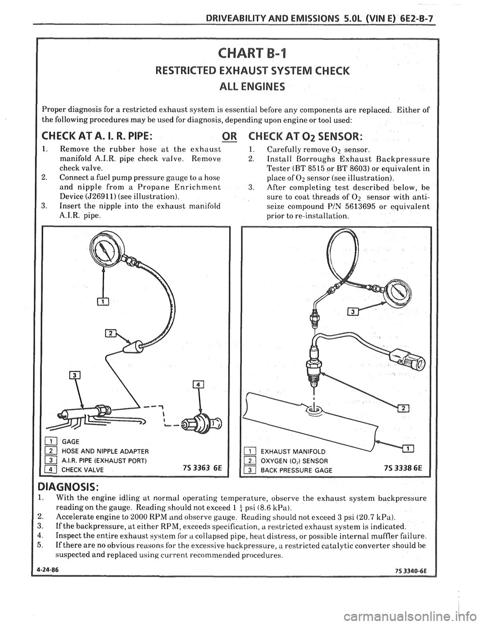
Proper diagnosis for a restricted exhaust system is essential before any components are replaced. Either of
the following procedures may be used for diagnosis, depending upon engine or tool used:
CHECK AT A. I. R. PIPE: - OR CHECK A"F2 SENSOR:
1. Remove the rubber hose at the exhaust 1. Carefully remove O2 sensor.
manifold
A.I.R. pipe check valve. Remove 2. Install Borroughs Exhaust Rackpressure
Tester
(FIT 8515 or BT 8603) or equivalent in
2. Connect a fuel pump pressure gauge to a hose
place of Oz sensor (see illustration).
and nipple from a Propane Enrichment
3. After completing test described below, be
Device
(526911) (see illustration).
sure to coat threads of O2 sensor with anti-
3. Insert the nipple into the exhaust manifold
seize compound PIN 5613695 or equivalent
prior to re-installation.
1. With the engine idling at normal operating temperature, observe the exhaust system backpressure
reading on the gauge. Reading should not exceed
1 t psi (8.6 kPa).
2. Accelerate engine to 2000 RPM and observe gauge. Reading should not exceed 3 psi (20.7 kPa).
3.
If the backpressure, at either RPM, exceeds specification, a restricted exhaust system is indicated.
4. Inspect the entire exhaust system for a collapsed pipe, heat distress, or possible internal muffler failure.
5. If there are no obvious reasons
for the excessive hackpressure, a restricted catalytic converter should be
suspected and replaced using
current recommended proceclures.