1988 PONTIAC FIERO catalytic converter
[x] Cancel search: catalytic converterPage 987 of 1825
6F-2 EXHAUST SYSTEM
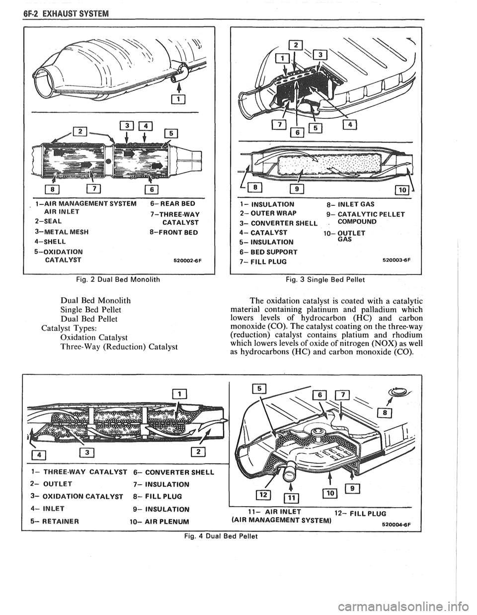
, 1 -AIR MANAGEMENT SVSTEM 6- REAR BED
7-THREE-WAY
3-METAL
MESH 8-FRONT BED
5-OXIDATION
Fig. 2 Dual Bed Monolith
Dual Bed Monolith
Single Bed Pellet
Dual Bed Pellet
Catalyst Types:
Oxidation Catalyst
Three-Way (Reduction) Catalyst
1 - INSULATION 8- INLET GAS
2- OUTER WRAP 9- CATALYTIC PELLET
3- CONVERTER SHELL
. COMPoIJND
4- CATALYST 10- OUTLET
5- INSULATION
6- BED SUPPORT
Fig. 3 Single Bed Pellet
The oxidation catalyst is coated with a catalytic
material containing platinum and palladium which
lowers levels of hydrocarbon (HC) and carbon
monoxide (CO). The catalyst coating on the three-way
(reduction) catalyst contains platium and rhodium
which lowers levels of oxide of nitrogen (NOX) as well
as hydrocarbons (HC) and carbon monoxide
(CO).
2- OUTLET 7- INSULATION I 3- OXIDATION CATALYST 8- FlLL PLUG I 4- INLET 9- INSULATION L
5- RETAINER 10- AIR PLENUM
11- AIR INLET 12- FILL PLUG
(AIR MANAGEMENT SYSTEM)
5200W8F
Fig. 4 Dual Bed Pellet
Page 1140 of 1825
5-SPEED 77MM TRANSMISSION 7B-3
ON-VEHICLE SERVICE
SHlR CONTROL LEVER
Remove or Disconnect
1. Screws from transmission shift lever boot
retainer and slide boot up lever.
2. Shift lever attaching bolts at transmission and
remove lever.
NOTICE: The upper lever is no longer threaded
to the lower lever. The levers are bonded
together. Separation of the levers will damage the
shifter requiring replacement of the shifter
assembly.
Install or Conned
1. Shift lever and attaching bolts to transmission.
2. Shift lever boot, boot retainer and retainer
screws to transmission.
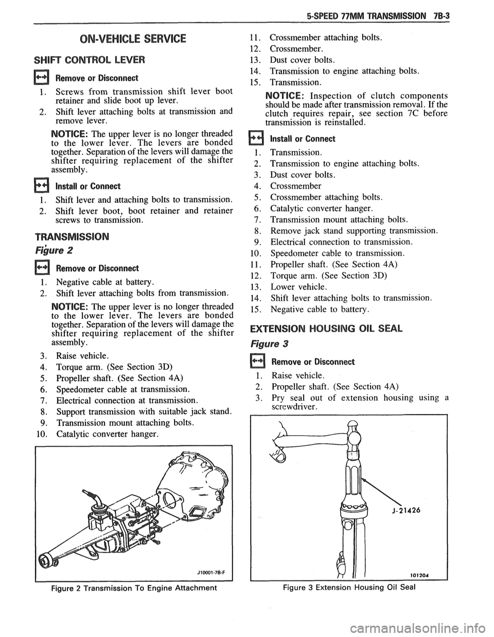
~ibure 2
Remove or Disconnect
1. Negative cable at battery.
2. Shift lever attaching bolts from transmission.
NOTICE: The upper lever is no longer threaded
to the lower lever. The levers are bonded
together. Separation of the levers will damage the
shifter requiring replacement of the shifter
assembly.
3. Raise vehicle.
4. Torque arm. (See Section 3D)
5. Propeller shaft. (See Section 4A)
6. Speedometer cable at transmission.
7. Electrical connection at transmission.
8. Support transmission with suitable jack stand.
9. Transmission mount attaching bolts.
10. Catalytic converter hanger.
Figure 2 Transmission To Engine Attachment
11. Crossmember attaching bolts.
12. Crossmember.
13. Dust cover bolts.
14. Transmission to engine attaching bolts.
15. Transmission.
NOTICE: Inspection of clutch components
should be made after transmission removal. If the
clutch requires repair, see section 7C before
transmission is reinstalled.
Install or Connect
Transmission.
Transmission to engine attaching bolts.
Dust cover bolts.
Crossmember
Crossmember attaching bolts.
Catalytic converter hanger.
Transmission mount attaching bolts.
Remove jack stand supporting transmission.
Electrical connection to transmission. Speedometer cable to transmission.
Propeller shaft. (See Section
4A)
Torque arm. (See Section 3D)
Lower vehicle.
Shift lever attaching bolts to transmission.
Negative cable to battery.
EXTENSlOM HOUSING OIL SEAL
Figure 3
Remove or Disconnect
1 . Raise vehicle.
2. Propeller shaft. (See Section 4A)
3. Pry seal out of extension housing using a
screwdriver.
Figure 3 Extension Housing Oil Seal
Page 1706 of 1825
UNDERBODY-F STYLE 3H-1
SECTION 3H
UNDERBODY
CONTENTS
General Body Construction .......................................................................................................... 3H- 1
Alignment Checking ................................................................................................................ 3H- I
Floor Pan Insulators ...................... .. ........................................................................................ 3H- 1
Floor Carpets ................................................................................................................................. 3H-2
metric-to-English dimensional conversion data.
Dimensions to gage holes are measured to dead center
GENERAL BODY CONSTRUCTION of the holes and flush to adjacent surface metal unless
Information in this section pertains to unitized otherwise specified.
body construction which
incorporates integral front
and rear frame side rails. FLOOR PAN INSULATORS
Consideration must be given when checking
underbody dimensions. The engine front suspension
lower control arms are supported by a cross member.
The cross member, in turn, is bolted to the body at six
locations
-- three on each side of the engine front
compartment lower rails. Mounting provisions for the
front suspension system are shared by chassis
components (suspension lower control arms and cross
member) and body components (engine compartment
side panels). The suspension strut towers must be
dimensionally correct in relation to the remainder of
the underbody in order to maintain specified
suspension strut and
castedcamber angles.
Since the individual underbody components also
contribute directly to the overall strength of the body,
it is essential that proper welding techniques be
observed during service repair operations. The
underbody components should be properly sealed and
rustproofed whenever body repair operations destroy
or damage the original sealing and rustproofing. When
rustproofing critical underbody components, it is
essential that a good quality type of air dry primer be
used (such as corrosion resistant chromate or
equivalent material). It is not advisable to use
combination type primer-surfacers.
ALIGNMENT CHECKING
An accurate method of determining the
alignment of the underbody utilizes a measuring tram
gage. The tram gage set required to perform the
recommended measuring checks must include a
vertical pointer capable of reaching 914 mm (36").
Two types of measurements can be made with
a
tram gage: direct point-to-point measurements and
measurements calculated on a horizontal
vlane (datum
line) parallel to the underbody. In the
latter case, the
vertical pointers must be set as specified for each point
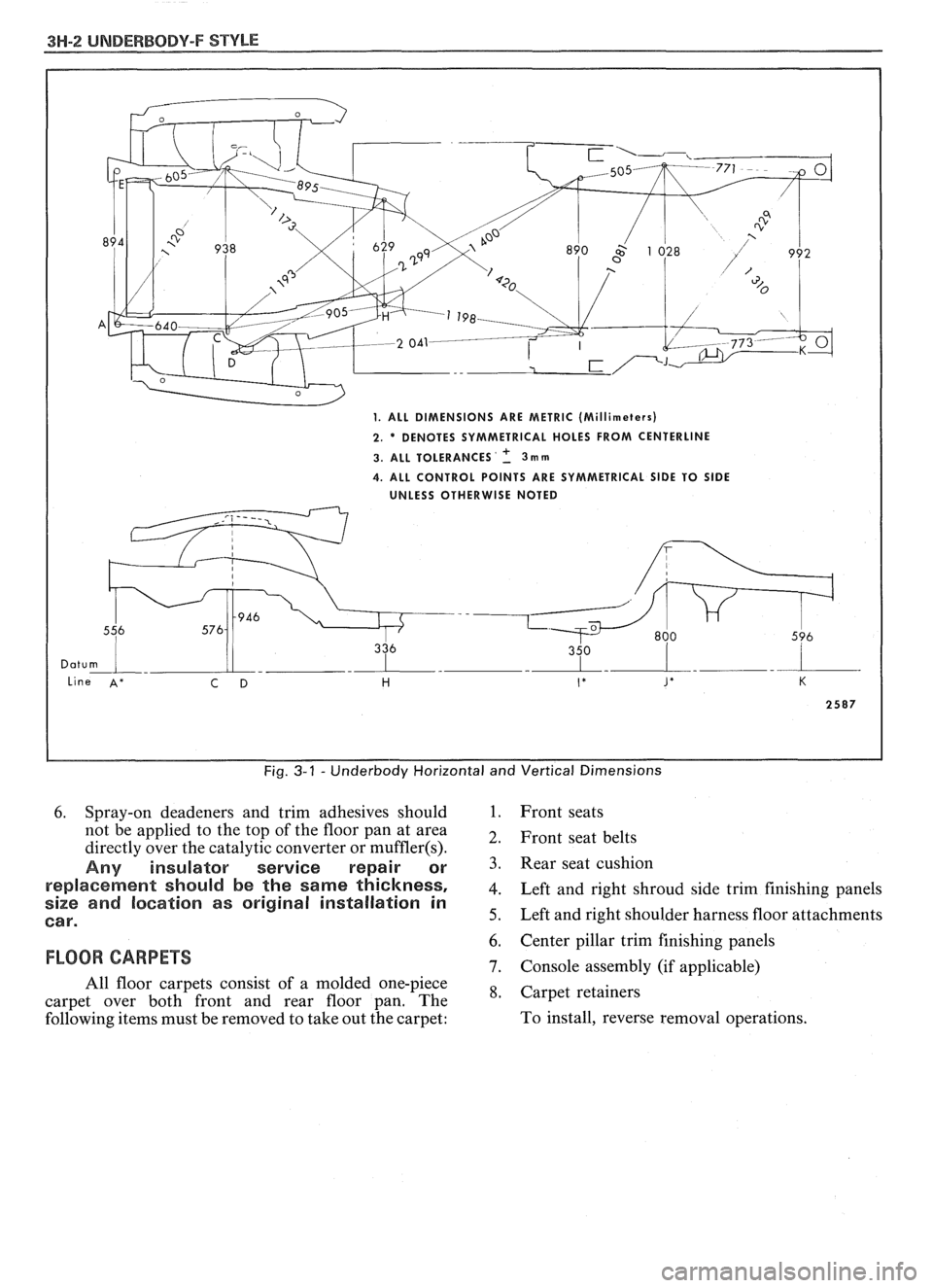
to be measured (Fig. 3-1).
Point-to-point measurements are generally taken
only on engine compartment components (Fig. 3-2)
and simply require the vertical pointers to be equally
set.
Figure #3-3 describes the alphabetically
identified points of measurement. Figure 3-4 provides Floor
pan insulators have been designed for the
higher floor pan temperatures that result from the use
of the catalytic converter in the exhaust system.
Therefore, when servicing a vehicle in the field, it is
essential that any insulators that may have been
disturbed or removed be reinstalled in the original
sequence and location. Also, if it becomes necessary to
replace an insulator, the material specified for that
particular location on the floor pan must be used. The
types of materials are listed below. Items 1 and
2 are
rolled stock and are ordered by linear foot and cut to
fit.
1. Insulator floor pan
(cerra blanket thermal) -
consists of 10 mm (3/8") thick aluminum silica
(type 1).
2. Insulator floor pan (amberlite) - consists of 10
mm
(3/8") thick resinated fibers (type 2).
3. Insulator floor pan sheet (phenolic bonded fiber
glass)
305 mm x 457 mm (12" x 18") cut to size,
(type 3).
All of the above materials must meet
Motor Vehicle Safety Standard No. 302 for
flammability.
When servicing or replacing interior insulators,
the following instructions must be observed:
1. Insulators must be installed in the original
position and sequence. Pieces should be butted
together in order to avoid gapping or
overlapping.
2. If it is necessary to replace an insulator, the
specified material must be used.
3. Use original
part to determine the amount of
replacement material required and as a template
for cutting and fitting the new piece to the floor
pan.
4. When installing insulator, do not enlarge cutouts
or holes that are used for the attachment of
interior components such as seats or seat belts.
5. Cross body harnesses for interior components
such as power seats, lap belt warning light and
buzzer or rear speakers must be routed over the
floor pan insulators in the original location and
clipped in place.
Page 1707 of 1825
3H-2 UNDERBODY-F STYLE
Fig. 3-1 - Underbody Horizontal and Vertical Dimensions
6. Spray-on deadeners and trim adhesives should 1. Front seats
not be applied to the top of the floor pan at area
2, Front seat belts directly over the catalytic converter or muffler(s).
Any insulator service repair or 3. seat cushion
re~laeement should be the same thickness, 4. Left and right shroud side trim finishing panels size and location as original installation in
Car. 5. Left and right shoulder harness floor attachments
6. Center pillar trim finishing panels
FLOOR CARPETS 7. Console assembly (if applicable)
All floor carpets consist of a molded one-piece
*, Carpet retainers carpet over both front and rear floor pan. The
following items must be removed to take out the carpet: To
install, reverse removal operations.
Page 1817 of 1825
2 - CHASSIS INDEX
Backup Lamp Switch (Circuit) .......... 8A- 1 12. 7A 1-5
Backup Lights
..................................................... 8B-1
...................................................... Battery Section 6D 1
............................ Battery Specification Chart 6D 1-7
.................................... Body Identification ... .... OA- 1
Borg Warner Rear Axle .......................... Section 4B1
...................................................... Blower Motor 1A-14
Blower Switch
.................................................... 1 A- 13
Booster Assembly
............................................. 5D2-2
Brakes
- General ......................................... Section 5
Adjustment
.................................................... 5C3-4
Booster Assembly
. Tandem
Diaphragm
................... .... ..................... 5D2- 1
................................................ Components 5C3- 1
Diagnosis and Inspection
................................. 5-3
Disc Brake Caliper Assembly
.................................................... 3548 Series 5B6-1
Drum Brake Assembly ........................ Section 5C3
General Description
.......................................... 5-2
On-Car Service
.................................................... 5-7
Specifications & Special Tools ......................... .5 F. 1
...................................................... Unit Repair 5A3- 1
.......................................... Warning System 8A-4 1-0
............ Brake Pedal Mounting .. ......................... 5-1 7
Bulb Usage Chart
............................................ 8B-10
............................................ Bumpers Section 2B,3 D.6
Bumper Energy Absorbing Units
.................... 2B-2
Bench Testing
................................................ 2B-3
........................................ Damage/Leakage 2B-3
................................ Removal After Collision 2B-2
............................................. Fascia Rub Strips .2 B. 1
.................................................... Front Bumper 2B-2
Assembly
........................................................ 2B-4
Energy Absorber
........................................... 2B-4
............................................................. Fascia .2 B. 1
On-Vehicle Service
...................................... 2B-4
Rear Bumper
.................................... .... ............ 2B-2
........................................................ Assembly 2B-5
Energy Absorber
............................................ 2B-4
............. .................... Fascia Molding Strip .. 2B-5 ........................................... Service Procedures .2 B. 1
.................................................. Specifications 2B-5
C
Caliper Assembly . Disc Brake
.............................................. 3000/3 100 Series 5B 1-2
3548 Series
...................................................... 5B6-2
Caliper Overhaul
....................... 3000/3 100 Series .. ............... 5B 1-4
3548 Series
.................................................... 5B6-5
Caster and Camber Adjustment
........................ 3A- 1
............................................. Catalytic Converter 6F-2
Center High-Mounted Stoplight
....................... ... 8B- 1
Charging System
...................... 8A.30.7, Section 6D3
Chassis Electrical
.................................... Section 8B
Center High Mounted Stoplight
...................... 8B-1 ................................. Exterior Light Monitor .8 B. 1
................................................................ Chimes 8A-77
................................ Cigar Lighter (Circuit) 8A- 1
14-0
.............................. Circuit Breaker Details Section 8A
Power ACC Circuit Breaker .... 8A- 10.1.10.3.10.5.
11-3
.... Window Circuit Breaker 8A~10~1,10~3.10~5.1 1.4
Clutch
........................................................ Section 7C
......................................... General Description .7 C. 1 ........................................................... Diagnosis 7C-2 Bleeding
Hydraulic Clutch System
................. .7 C.2
Preliminary Checks ..................................... ... 7C-2
On-Vehicle Service
........................................... 7C-5
Clutch Hydraulic System
.................................. 7C-5
Clutch Pedal ...................................................... 7C-6
Pilot Bearing
..................................................... 7C-6
Pressure Plate and Disc
.................................... 7C-6
Special Tools
......................... ....... ................ 7C-8
Specifications
................................................... 7C-8
Coil Springs and Insulators .............................. 3D-1
Component Fluid Capacities
................................ OB-6
Component Location Views
........................ 8A-201-0
Composite Master Cylinder
................... Section 5A3
Compression Test
.................. .. ............................. 6-5
Condenser Mounting
....................................... 1B 1-24
Connectors
.................................................... 8A-202-0
Coolant Fan Temperature Switch
...................... 8A-3 1
Cooling and Radiator
................................ Section 6B
Cooling System Capacities
................................. OB-6
Cooling System Diagnosis
.................................... 6B-3
Cranking System
...................................... Section 6P*
Diagnosis ..................................................... 6~2
General Description ................................ 6D2- 1
Cranking System
........................................ 6D2- 1
Solenoid
................................................... 6D2- 1
Starter Motor ......................................... 6D2-1
On-Vehcile Service
...................................... 6D2-4
Specifications
............................................ 6D2- 1
Starter
........................................................ 6D2-4
Unit Repair
............................................ 6D2-6- 11
Service Procedures
...................................... 6D2-3
Cruise Control
.............................. 8A-34-0, Section 9B
Diagnosis
............................................................ 9B-4
Cruise Set Speed High or Low
.................... 9B-4
Cruise System Surges
.................................. 9B-4
Cruise Tap-Up and Tap-Down
...................... 9B-4
Excessive Cruise Speed Loss on
Hills
........................................................... 9B-4
General Description
........................................ 9B-1
Electrical and Vacuum Release
Switches
...................................................... 9B-4
Electrical Harness
.......................................... 9B-A
Electronic Controller (Module) .................... 9B .
Off/On/Resume/Accel Switch
Operation
.................................................. .91 B-
Servo Unit
.................................................... 9B-2
Set/Coast Button Switch .............................. 9B-1
................................................ Speed Sensors 9B-3
Vacuum Supply
............................................ 9B-4
On-Car Service
.................................................. 9B-6
................................ Cruise Release Switches 9B-6
.......................................... Servo Mounting 9B-10
Vacuum Harness and Cable Routing
VIN
E ................................. .. .................. 9B,7
.................................................... VIN F, 8 9B-9
....................................................... VIN S 9B-8
........................ Vacuum Tank - VIN S,F,E, 9B-10
.............................. Cruise Control (Circuit) 8A-34-0
D
......................................... Defogger (Circuit) $A-6 1-0
..................... ...... Defroster Duct Assembly ... .812 C-
Diagnosis
Air Conditioning
- General ........................... 1B-5
.................... Automatic Transmission - General 7A
Automatic Transmission
- ................ HD-700-R4-2
Page 1819 of 1825
4 . CHASSIS INDEX
Fitting Pistons ......................................... .6A 2.24
Front (Cover) Crankshaft Oil
Seal
V-6
......................................................... 6A2- 15
V-8
................................................... 6A3- 16
Gear or Sprocket
V-6
......................................................... .6A 2.26
V-8
........................................................ 6A2-28
Honing and Reboring Cylinders ................ 6A2-23
Intake Manifold and Gasket
V-6
......................................................... .6A 2.9
V-8
............................................................ 6A3-6
Main Bearings
V-6
......................................................... .6A 2. 19
V-8
.......................................................... 6A3-20
Oil Filter and Bypass Valve
...................... 6A3-27
Oil Pan and Pump Assembly
V-6
................................................. 6A2.17, 18
V-8
......................................................... 6A3- 18
Oil Seal (Front Cover)
V-6
......................................................... 6A2- 15
V-8 .......................................................... 6A3-16
Piston and Connecting Rod
V-6
......................................................... .6A 2.2 1
V-8
....................................................... .6A 3.23
Piston Rings V-6
......................................................... .6A 2.24
V-8
........................................................ .6A 3.23
Power Train Mounts
V-6
........................................................... .6A 2.7
V-8
.......................................................... 6A3-5
Rear Main Oil Seal
V-6
......................................................... .6A 2.2 1
V-8 ......................................................... .6A 3.22
Rocker Arm Assembly
V-6
............................................................ 6A2-8
V-8 ............................................................ 6A3-8
Rocker Arm and Push Rod
V-6
........................................................... .6A 2.8
V-8
........................................................ 6A3-8
Rocker Arm Studs 6A2- 13
V-6
......................................................... .6A 2. 13
V-8
.......................................................... 6A3-28
Sprocket or Gear Replacement
V-6
......................................................... .6A 2.26
V-8 .......................................................... 6A3-28
Timing Chain and Sprockets
6A2- 15
Torsional Damper
V-6
.......................................................... 6A2- 14
V-8
.......................................................... 6A3- 15
Valves V-6
........................................ .. ............... .6A 2. 14
V-8
......................................................... .6A 2. 15
Valve Guides
V-6
......................................................... .6A 2. 13
V-8
.......................................................... 6A3-14
Valve Lifters
V-6
......................................................... .6A 2. 1 1
V-8
.......................................................... 6A3-10
Valve Mechanism .................................... 6A 10
Valve Seats
V-6
....................................................... .6A 2. 14
V-8
.......................................................... 6A3-14
Valve Spring
.......................................................... V-6 A- 16
............................................................ V-8 6A3-9
................................. Valve Stem Oil Seal .6A 2. 10 Engine Cooling
........................................... Section
6B
Aluminum Radiator Service
............................ 6B-8
Diagnosis
........................................................ 6B-3. 8
Coolant System .............................................. 6B-4
Leak Testing
.................................................. 6B-8
On-Vehicle Pressure Testing
.......................... 6B-9
Repair Methods
........................................... 6B- 10
Special Tools
.............................................. 6B-14
General Description ......................................... .6 B- 1
Coolant Recovery System
.............................. 6B-3
Coolant Temperature Fan Switch
................ 6B-2
Fans
.............................................................. 6B-2
Radiator
...................................................... 6B-1
Radiator Cap
.................................................. 6B-1
Recovery Bottle
.............................................. 6B-2
Temperature Switch
...................................... 6B-2
Thermostat
.................................................... 6B-3
On-Vehicle Service
......................................... 6B- 14
Coolznt Recovery Bottle
............................. .6 B- 16
Electric Cooling Fan
................................... .6 B- 15
Radiator
....................................................... 6B1'
Thermostat ................................................ 5B-, .
Water Pump ................................... .... ......... 6B-15
Service Procedures
............................................ 6B-3
Cooling System Cure
................................. ... 6B-3
Draining and Refilling the
Cooling System
......................................... 6B-7
Drive Belt
................................................... 6B-7
Engine Electrical ...................................... Section 6D
Battery
............................................................. 6D1
Diagnosis
................................................... 6D 1-2
General Description
.................................. 6D 1-1
On-Car Service
.......................................... 6D 1-5
Charging System
............................................... 6D3
Diagnosis
.................................................... 6D3- 1
General Description
.............................. 6D3- 1
On-Vehicle Service
.................................... 6D3-2
Service Procedures
................................. 6D3- 1
Cranking System .......................... ........ ............ 6D2-
Diagnosis .................................................... 6D2- 1 I
General Description .................................. 6D2- 1
On-Car Service
......................................... 6D2J
................ . Engine Wiring .............................. ... 6D
General Description .................................. 6D5- 1
Ignition System
................................................. 6D4
Diagnosis
................................................... 6D4- 1
General Description
............................... 6D4- 1
On-Car Service
.......................................... 6D4-5
Service Procedures
.................................... 6D4-3
Engine Exhaust Systems
...................................... 6F
Engine
- General Information .............................. 6-1
Compression Test
................................................ 6-5
Engine Knock Diagnosis
................................. 6-4
Engine Mechanical
.............................................. 6-3
Engine Performance Diagnosis
.......................... 6-3
Engine Oil Pressure Light
.................................... 8C-3
Engine Performance Specifications
Chart
........................................................ 6E3-C13-3
Evaporator Core
.............................................. 1B 1-24
Exhaust Systems
.......................................... Section 6F
Catalytic Converters
........................................ 6F- 1
Clamp
................................................................ 6F- 1
Component Replacement
.................................. 6F-2
Hangers
......................................................... 6F- 1
Muffler ............................................................. 6F- 1
Removing and Installing Parts ........................ 6F-2
Resonator .......................................................... 6F- 1