1988 PONTIAC FIERO degrees
[x] Cancel search: degreesPage 515 of 1825
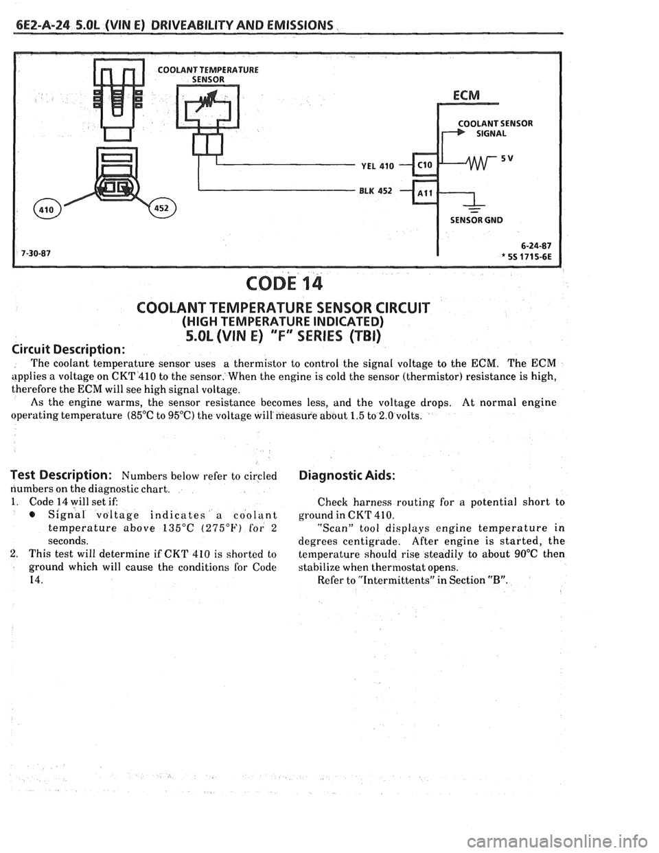
bE2-A-24 S.OL (VIN E) DRIVEABILITY AND EMlSSlONS
SENSOR GND
COD^ 14
COOLANT TEMPERATURE SENSOR CIRCUIT
(HIGH TEMPERATURE INDICATED)
5.OL (VIN E) "F"" SERIES (TBI)
Circuit Description:
The coolant temperature sensor uses a
thermistor to control the signal voltage to the ECM. The ECM
applies a voltage on CKT4410 to the sensor. When the engine is cold the sensor (thermistor) resistance is high,
therefore the
ECM will see high signal voltage.
As the engine warms, the sensor resistance becomes less, and the voltage drops. At normal engine
operating temperature
(85°C to 95OC) the voltage will'measure about 1.5 to 2.0 volts.
Test Description: Numbers below refer to circled
numbers on the diagnostic chart.
1. Code 14 will set if:
s Signal voltage indicates a coolant
temperature above
135°C (275°F) for 2
seconds.
2. This test will determine if CKT 410 is shorted to
ground which will cause the conditions for Code
14.
Diagnostic Aids:
Check harness routing for a potential short to
ground in CKT
41 0.
"Scan" tool displays engine temperature in
degrees centigrade. After
engine is started, the
temperature should rise steadily to about
90°C then
stabilize when thermostat opens.
Refer to "Intermittents" in Section
"B".
Page 517 of 1825
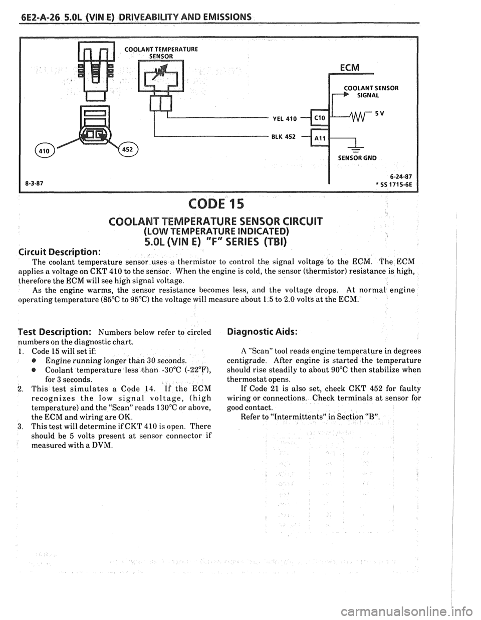
6EZ-A-26 5.8L (VIN E) DRIVEABILITY AND EMISSIONS
OLANT SENSOR
SENSOR GND
CODE 15
Test Description: Numbers below refer to circled
numbers on the diagnostic chart.
1. Code 15 will set if:
@ Engine running longer than 30 seconds.
@ Coolant temperature less than -30°C (-22"F),
for 3 seconds.
2. This test simulates a Code 14. If the ECM
recognizes the
low signal voltage, (high
temperature) and the "Scan" reads 130°C or above,
the ECM and wiring are OK.
3. This test will determine if CKT 410 is open. There
should be 5 volts present at sensor connector if
measured with a
DVM.
COOLANT TEMPERATURE SENSOR CIRCUIT
(LOMI TEMPERATURE INDICATED)
5.OL (VIM E) ""FYERIES (TBI)
Diagnostic Aids:
Circuit
Description:
The coolant temperature sensor uses a thermistor to control the signal voltage to the ECM. The ECM
applies a voltage on CKT 410 to the sensor. When the engine is cold, the sensor (thermistor) resistance is high,
therefore the ECM will see high signal voltage.
As the engine warms, the sensor resistance becomes less, and the voltage drops. At
normal engine
operating temperature (85°C to 95°C) the voltage will measure about 1.5 to 2.0 volts at the ECM.
A "Scan" tool reads engine temperature in degrees
centigrade. After engine is started the temperature
should rise steadily to about 90°C then stabilize when
thermostat opens.
If Code 21 is also set, check CKT 452 for faulty
wiring or connections. Check terminals at sensor for
good contact.
Refer to "Intermittents" in Section
"B".
~
Page 560 of 1825
DRIVEABILITY AND EMISSIONS 5.OL (VIN E) 6EZ-C1-5
DIAGNOSIS
Since the ECM can have a failure which may
effect only one circuit, following the diagnostic
procedures in this section can reliably tell when a
failure has occurred in the ECM. Also,
a Code
55 in
dicates a failure of the ECM.
If a diagnostic chart indicates that the ECM
connections or ECM is the cause of a
problem,and the
ECM is replaced, but does not correct the problem, one
of the following may be the reason:
e
connections. - The diagnostic chart will say "ECM
Connections or ECM". The terminals mav have to be
removed from the connector in order to check them
properly.
@ The ECM or PROM is not correct for the
. - The incorrect ECM or PROM may cause
a malfunction and may or may not set a code.
. - This means that
time the system is
being checked. In this case, refer to the "Symptoms"
portion of the manual and make a careful physical
Solenoids and relays are turned "ON" and "OFF" by
the ECM, using internal electronic switches called
"Drivers".
A shorted solenoid, relay coil, or harness in a
GMP4 computer will not damage the ECM,
but will cause the circuit and controlled
component to be inoperative. When the
circuit fault is not present or has been
repaired, the "Quad-Driver" will again
operate in a normal manner due to it's fault
protected design. If a fault has been repaired
in a circuit controlled
by a "Quad-Driver", the
original
ECM should be reinstalled and the
circuit checked for proper operation.
ECM
replacement will not be necessary if the
repaired circuit or component now operates
correctly.
534636 or BT8405 testers or equivalent provide a
fast, accurate means of checking for a shorted coil or a
short to battery voltage.
e , - Although the
PROM rarely
fails,it operates as part of the ECM.
Therefore, it could be the cause of the problem.
Substitute a known good PROM.
o . - After the
ECM is replaced, the system should be rechecked for
proper operation. If the diagnostic chart again
indicates the ECM is the problem, substitute a known
good ECM. Although this is a rare condition, it could
happen. The
components or circuits and the codes or
charts, related to them are:
@ Code 55 indicates a failure of the ECM.
@ PROM - Code 51.
@ Coolant Temperature Sensor - CHARTS 14 -
15.
@ MAP sensor - CHART 33 or 34. To check the
sensor with no code set, use CHART
C-1D.
e TPS - CHARTS 21 or 22.
e PIN switch - CHART C-1A
@ Crank Signal - CHART C-1B
@ O2 Sensor - CHARTS 13,44,45.
@ VSS - CHART 24 and in TCC System.
e Distributor - CHART 42 and in EST system.
@ Distributor - Chart and in the EST system.
ECM
A faulty ECM will be determined in the diagnostic
charts, or by a Code 55.
PROM
An incorrect or faulty PROM, which is part of the
ECM, may set a Code 51.
ECM INPUTS
All of the sensors and input switches can be
diagnosed by the use of a "Scan" tool. Following is
a
short description of how the sensors and switches can
be diagnosed by the use of "a Scan" tool. The
"Scan"
tool can also by used to compare the values for a
normal running engine with the engine you're
diagnosing.
Coolant Temperature Sensor
A "Scan" tool displays engine temp. in degrees
centigrade. After the engine is started, the
temperature should rise steadily to about
90°C, then
stabilize when thermostat opens.
A fault in the
coolant sensor circuit should set a Code 14 or 15. The
code charts also contain a chart to check for sensor
resistance values relative to temperature.
MAT Sensor
A "Scan" tool displays temperature of the air
entering the engine and should read close ambient air
temperature, when engine is cold, and rise
as
underhood temperature increases. If the engine has
not been run for several hours (overnight), the MAT
sensor temperature and coolant temperature should
read close to each other.
Page 661 of 1825
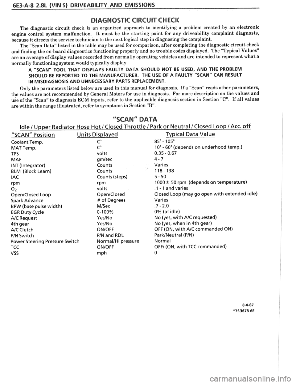
DIAGNOSTIC CIRCUIT CHECK
The diagnostic circuit check is an organized approach to identifying a problem created by an electronic
engine control system malfunction. It
must be the starting point for any driveability complaint diagnosis,
because it directs the service technician to the next logical step in diagnosing the complaint.
The "Scan Data" listed in the table may be used for comparison, after completing the diagnostic circuit check
and finding the on-board diagnostics functioning properly and no trouble codes displayed. The "Typical Values"
are an average of display values recorded from normally operating vehicles and are intended to represent what a
normally functioning system would typically display.
A "SCAN" TOOL THAT BiSPLAYS FAULTY DATA SHOULD NOT BE USED, AND THE PROBLEM
SHOULD BE REPORTED
TO THE MANUFACTURER. THE USE OF A FAULTY "SCAN" CAN RESULT
IN MISDIAGNOSIS AND UNNECESSARY PARTS REPLACEMENT.
Only the parameters listed below are used in this manual for diagnosis. If a "Scan" reads other parameters,
the values are not recommended by General Motors for use in diagnosis. For more description on the values and
use of the "Scan" to diagnosis
ECM inputs, refer to the applicable diagnosis section in Section "C". If all values
are within the range illustrated, refer to symptoms in Section
"B".
""SCAN" DATA
Coolant Temp. CO 85" - 105"
MAT Temp. C0 10" - 60" (depends on underhood temp.)
TPS
volts 0.35 - 0.67
MAF
gmlsec 4-7
INT (Integrator) Counts Varies
BLM (Block Learn) Counts 118- 138
IAC Counts (steps) 5-50
rPm rPm 1000 ? 50 rpm (depends on temperature)
0 2 volts .I - 1 and varies
OpenIClosed Loop OpenIClosed Closed Loop (may go open with extended idle)
Spark Advance
# of Degrees Varies
BPW (base pulse width) MISec .7 - 2.0
EGR Duty Cycle 0-
100% 0%
(at idle)
NC Request YesINo No (yes, with NC requested)
4th gear
YesINo No (yes, when in 4th gear)
NC Clutch ONIOFF OFF (ON, with NC commanded ON)
PIN Switch PIN
and
RBL ParkINeutral (PIN)
Power Steering Pressure Switch
NormalIHI pressure Normal
TCC
ONIOFF OFF1 (ON, with TCC commanded)
VSS mph 0
Page 679 of 1825
6E3-A-26 2.8L (VIN 5) DRIVEABILITY AND EMISSIONS
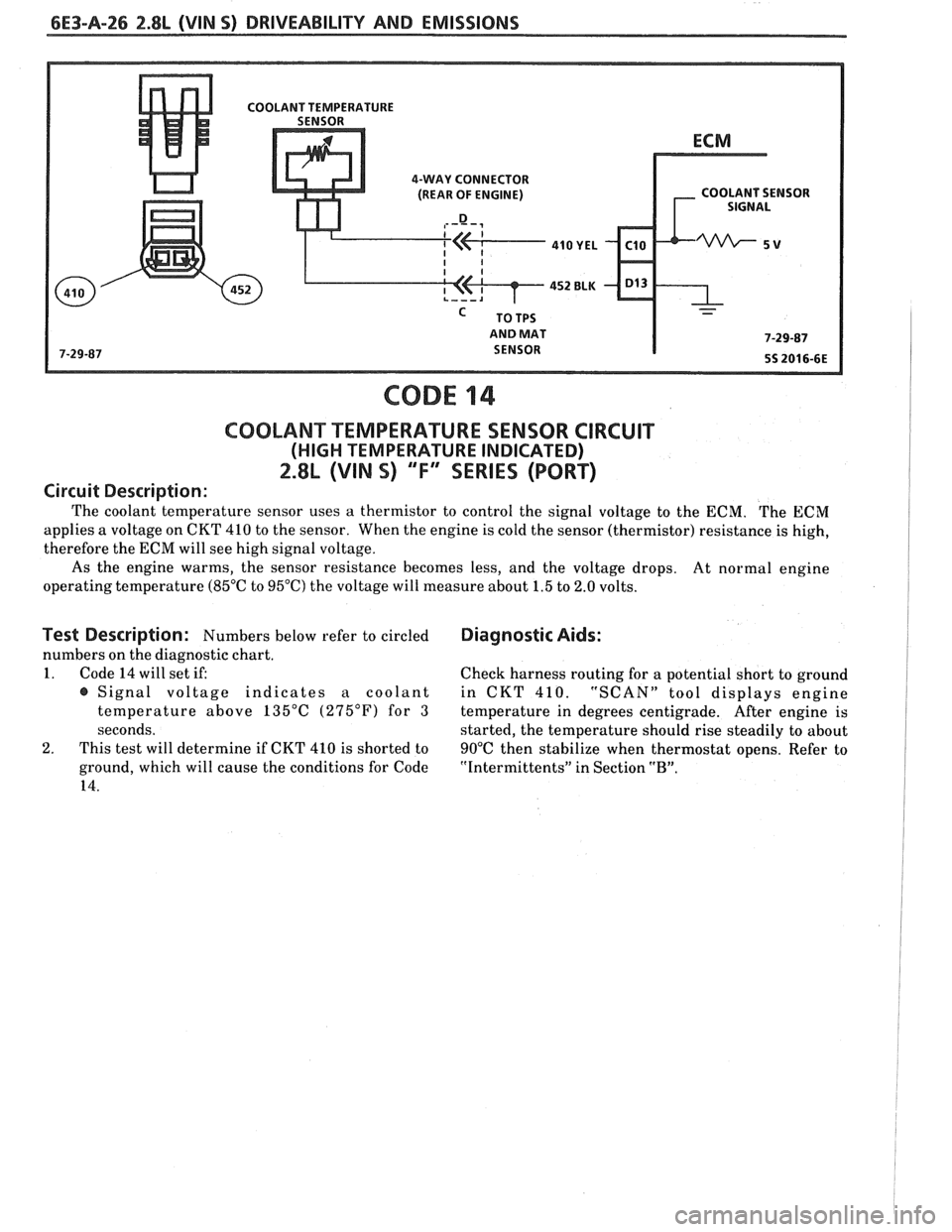
4-WAY CONNECTOR
(REAR OF ENGINE) COOLANT SENSOR
AND MAT
CODE 14
COOLANT TEMPERATURE SENSOR CIRCUIT
(HIGH TEMPERATURE INDICATED)
2.8L (VIN S) ""F-SERIES (PORT)
Circuit Description:
The coolant temperature sensor uses a thermistor to control the signal voltage to the ECM. The ECM
applies a voltage on CKT 410 to the sensor. When the engine is cold the sensor (thermistor) resistance is high,
therefore the ECM will see high signal voltage.
As the engine warms, the sensor resistance becomes less, and the voltage drops.
At normal engine
operating temperature (85°C to 95°C) the voltage will measure about 1.5 to 2.0 volts.
Test Description: Numbers below refer to circled Diagnostic Aids:
numbers on the diagnostic chart.
1. Code 14 will set if:
Check harness routing for a potential short to ground
@ Signal voltage indicates a coolant in CKT 410. "SCAN" tool displays engine
temperature above 135°C (275°F) for
3 temperature in degrees centigrade. After engine is
seconds. started, the temperature should rise steadily to about
2. This test will determine if CKT 410 is shorted to
90°C then stabilize when thermostat opens. Refer to
ground, which will cause the conditions for Code
"Intermittents" in Section "B".
14.
Page 681 of 1825
6E3-A-28 2.8L (VIN S) DRIVEABILITY AND EMISSIONS
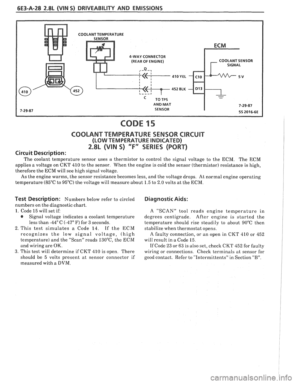
4-WAY CONNECTOR
(REAR OF ENGINE) COOLANT SENSOR
AND MAT
CODE 15
C0OLAN"FT"EMPERAWURE SENSOR CIRCUIT
(LOW TEMPERATURE INDICATED)
2.8L (VIN S) 'Tf3SEWlES (PORT)
Circuit Description:
The coolant temperature sensor uses a thermistor to control the signal voltage to the ECM. The ECM
applies a voltage on CKT 410 to the sensor. When the engine is cold the sensor (thermistor) resistance is high,
therefore the ECM will see high signal voltage.
As the engine warms, the sensor resistance becomes less, and the voltage drops. At normal engine operating
temperature
(85OC to 95°C) the voltage will measure about 1.5 to 2.0 volts at the ECM.
Test Description : Numbers below refer to circled
numbers on the diagnostic chart.
1. Code 15 will set if:
@ Signal voltage indicates a coolant temperature
less than
-44" C (-47" F) for 3 seconds.
2. This test simulates a Code 14. If the
ECM
recognizes the low signal voltage, (high
temperature) and the "Scan" reads
130°C, the ECM
and wiring are OK.
3. This test will determine if CKT 410 is open. There
should be 5 volts present at sensor connector if
measured with
a DVM.
Diagnostic Aids:
A "SCAN" tool reads engine temperature in
degrees centigrade. After engine is started the
temperature should rise steadily to about 90°C then
stabilize when thermostat opens.
A faulty connection, or an open in CKT 410 or 452
will result in a Code
15.
If Code 23 or 63 is also set, check CK'I' 452 for faulty
wiring or connections. Check terminals at sensor for
good contact. Refer to "intermittents" in Section
"B".
Page 724 of 1825
DRIVEABILITY AND EMlSSlQNS 2.8L (VIN S) 6E3-C1-5
ECM Inputs
All of the sensors and input switches can be
diagnosed by the use of a "Scan" tool. Following is a
short description of how the sensors and switches can
be diagnosed by the use of "Scan".
The "Scan" can
also be used to compare the values for a normal
running engine with the engine you're diagnosing.
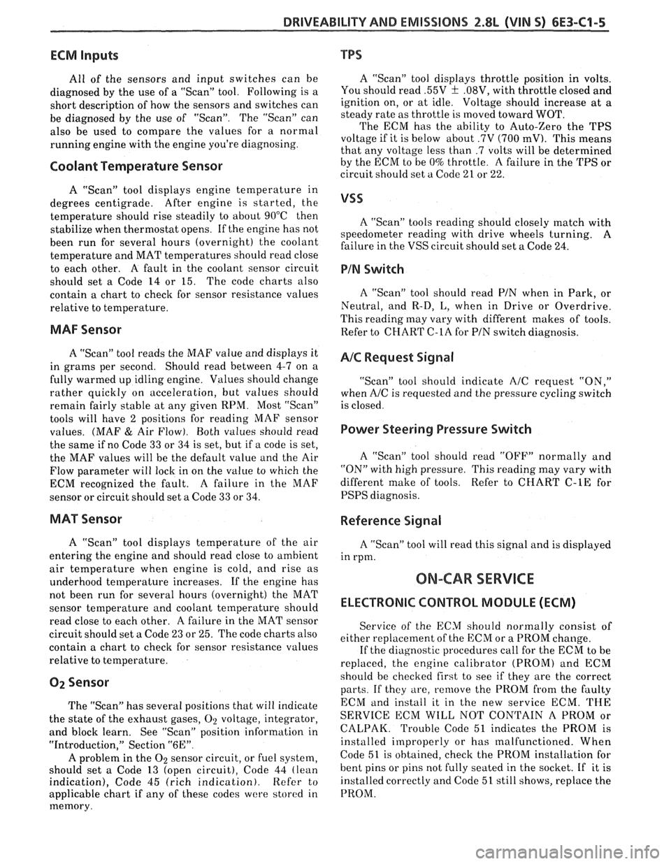
Coolant Temperature Sensor
A "Scan" tool displays engine temperature in
degrees centigrade. After
engine is started, the
temperature should rise steadily to about 90°C then
stabilize when thermostat opens. If the engine has not
been run for several hours (overnight) the coolant
temperature and MAT temperatures should read close
to each other. A fault in the coolant sensor circuit
should set a Code
14 or 15. The code charts also
contain a chart to check for sensor resistance values
relative to temperature.
MAF Sensor
A "Scan" tool reads the MAF value and displays it
in grams per second. Should read between 4-7 on a
fully warmed up idling engine. Values should change
rather quickly on acceleration, but values should
remain fairly stable at any given RPM. Most "Scan"
tools will have 2 positions for reading
MAE' sensor
values. (MAF
& Air Flow). Both values should read
the same if no Code 33 or 34 is set, but if a code is set,
the MAF values will be the default value and the Air
Flow parameter will lock in on the value to which the
ECM recognized the fault. A failure in the MAF
sensor or circuit should set a Code 33 or 34.
MAT Sensor
A "Scan" tool displays temperature of the air
entering the engine and should read close to ambient
air temperature when engine is cold, and rise as
underhood temperature increases. If the engine has
not been run for several hours (overnight) the MAT
sensor temperature and coolant temperature should
read close to each other. A failure in the MAT sensor
circuit should set
a Code 23 or 25. The code charts also
contain a chart to check for sensor resistance values
relative to temperature.
02 Sensor
The "Scan" has several positions that will indicate
the state of the exhaust gases,
O1! voltage, integrator,
and block learn. See "Scan" position information in
"Introduction," Section
"6E".
A problem in the O2 sensor circuit, or fuel system,
should set a Code 13 (open circuit), Code 44 (lean
indication), Code 45 (rich indication). Refer to
applicable chart if any of these codes
were stored in
memory.
TPS
A "Scan" tool displays throttle position in volts.
You should read
.55V f .08V, with throttle closed and
ignition on, or at idle. Voltage should increase at
a
steady rate as throttle is moved toward WOT.
The ECM has the ability to Auto-Zero the TPS
voltage if it is below about .7V (700
mV). This means
that any voltage less than
.7 volts will be determined
by the ECM to be
0% throttle. A failure in the TPS or
circuit should set a Code 21 or 22.
A "Scan" tools reading should closely match with
speedometer reading with drive wheels turning.
A
failure in the VSS circuit should set a Code 24.
PIN Switch
A "Scan" tool should read PIN when in Park, or
Neutral, and R-D, L, when in Drive or Overdrive.
This reading may vary with different makes of tools.
Refer to CHART
C-1A for PIN switch diagnosis.
NC Request Signal
"Scan" tool should indicate A/C request "ON,"
when A/C is requested and the pressure cycling switch
is closed.
Power Steering Pressure Switch
A "Scan" tool should read "OFF" normally and
"ON" with high pressure. This reading may vary with
different make of tools. Refer to CHART
C-1E for
PSPS diagnosis.
Reference Signal
A "ScanJ' tool will read this signal and is displayed
in rpm.
ON-CAR SERVICE
ELECTRONIC CONTROL MODULE (ECM)
Service of the ECM should normally consist of
either replacement of the ECM or a PROM change.
If the diagnostic
procedures call for the ECM to be
replaced, the engine calibrator (PROM) and ECM
should be checked first to see if they are the correct
parts. If they are, remove the PROM from the faulty
ECM
and install it in the new service ECM. THE
SERVICE ECM WILL NOT CONTAIN A PROM or
CALPAK. Trouble Code 51 indicates the PROM is
installed improperly or has malfunctioned. When
Code
51 is obtained, check the PROM installation for
bent pins or pins not fully seated in the socket. If it is
installed correctly and Code 51 still shows, replace the
PROM.
Page 811 of 1825
6E3-A-8 5.OL (VIN F) & 5.7L(VIN 8) DRIVEABILITY AND EMISSIONS
DIAGNOSIC CIRCUIXCHECK
The Diagnostic Circuit Checlc is an organized approach to identifying a problem created by an Electronic
Engine Control System malfunction. It
must be the starting point for any driveability complaint diagnosis,
because it directs the Service Technician to the next logical step in diagnosing the complaint.
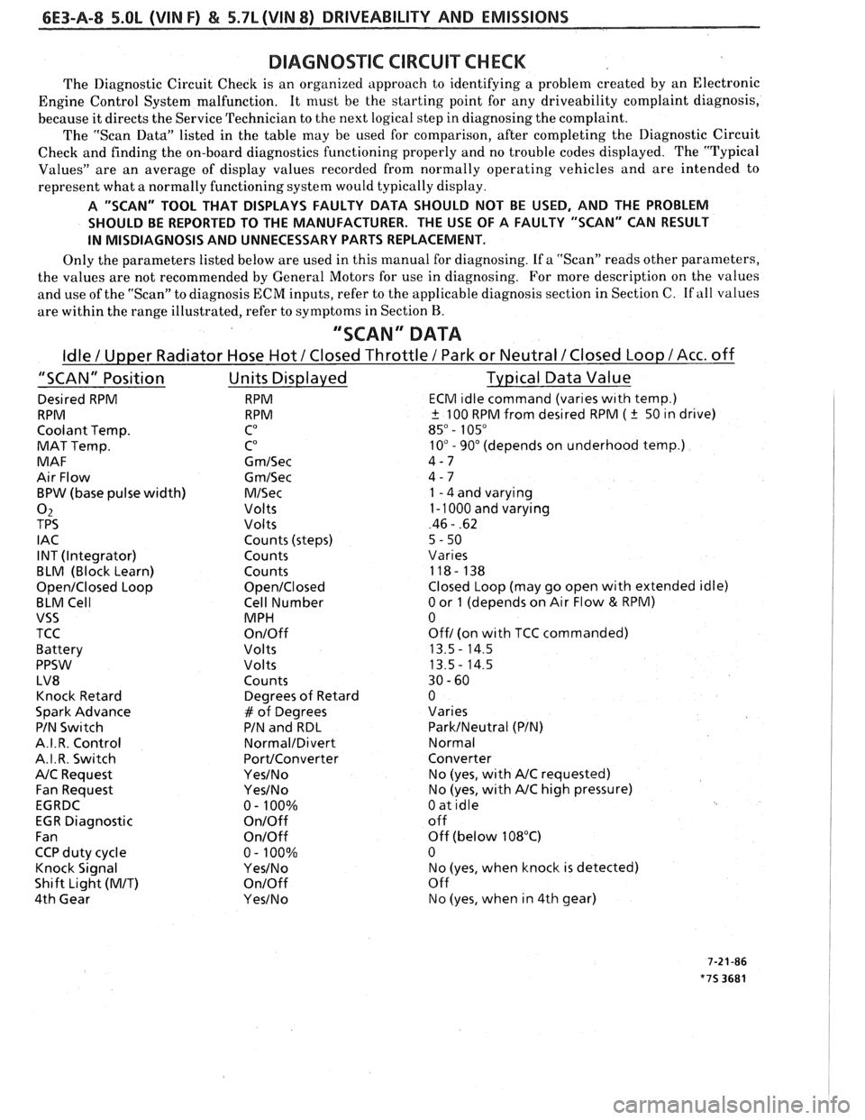
The "Scan Data" listed in the table may be used for comparison, after completing the Diagnostic Circuit
Check and finding the on-board diagnostics functioning properly and no trouble codes displayed. The "Typical
Values" are an average of display values recorded from normally operating vehicles and are intended to
represent what a normally functioning system would typically display.
A "SCAN" TOOL THAT DISPLAYS FAULTY DATA SHOULD NOT BE USED, AND THE PROBLEM
SHOULD BE REPORTED TO THE MANUFACTURER. THE USE OF A FAULTY "SCAN" CAN RESULT
IN MISDIAGNOSIS AND UNNECESSARY PARTS REPLACEMENT.
Only the parameters listed below are used in this manual for diagnosing. If a "Scan" reads other parameters,
the values are not recommended by General Motors for use in diagnosing. For more description on the values
and use of the "Scan" to diagnosis ECM inputs, refer to the applicable diagnosis section in Section C.
If all values
are within the range illustrated, refer to symptoms in Section
B.
"SCAN" DATA
Idle / Upper Radiator Hose Hot / Closed Throttle / Park or Neutral /Closed Loop /Acc. off
"SCAN" Position Units Displayed Typical Data Value
Desired RPM RPM ECM ~dle command (vanes w~th temp.)
RPM RPM
+ 100 RPM from desired RPM ( k 50 ~n drive)
Coolant Temp.
CO 85" - 105"
MAT Temp. CO 10" - 90" (depends on underhood temp.)
MAF G
m/Sec 4-7
Air Flow
Gm/Sec 4 - 7
BPW (base pulse width)
M/Sec 1 - 4 and varying
02 Volts 1 - 1000 and varying
TPS Volts 46 - .62
I AC Counts (steps)
5 - 50
INT (Integrator) Counts
Vanes
BLM (Block Learn) Counts 118- 138
Open/Closed Loop Open/Closed Closed Loop (may go open with extended idle)
BLM Cell Cell Number
0 or 1 (depends on Air Flow & RPM)
VSS MPH 0
TCC
On/Off Off/ (on wlth TCC commanded)
Battery Volts 13.5
- 14.5
PPSW
Volts 13.5- 14.5
LV8 Counts 30
- 60
Knock Retard Degrees
of Retard 0
Spark Advance
# of Degrees Varies
PIN
Swltch PIN and RDL ParkINeutral (PIN)
A.I. R. Control
Normal/Divert Normal
A.I.R. Switch
PortIConverter Converter
NC Request Yes/No No (yes, wlth NC requested)
Fan Request
Yes/No No (yes, with NC high pressure)
EGRDC 0- 100%
0 at idle
EGR Diagnostic
On/Off off
Fan
OnIOff Off (below 108°C)
CCP duty cycle 0
- 100% 0
Knock Signal
YesINo No (yes, when knock is detected)
Shift Light
(MIT) On/Off Off
4th Gear
Yes/No No (yes, when in 4th gear)