1988 PONTIAC FIERO ECO mode
[x] Cancel search: ECO modePage 2 of 1825
1988
SER
This manual applies to the 1988 Pontiac Firebird Models.
It contains the latest product information available at the
time of publication approval. lnformation pertaining to
the operation of the vehicle is contained in the Owner's
Manual which accompanies each vehicle. The right is
reserved to make changes at any time without notice.
Any references to brand names in this manual is intended
merely as an example of the types of
lubricant% tools,
materials, etc, recommended for use in servicing 1988
Pontiac Models. In all cases, an equivalent may be used.
PONTIAC DIVISION
GENERAL
MOTORS CORPORATION
PONTIAC, MICHIGAN 48053
1987 General Motors Corp. All Rights Reserved.
No part of this publication may be reproduced, stored in any
retrieval system or transmitted in any form or by any means,
including but not limited to electronic, mechanical,
photocopying, recording or otherwise, without the prior written
permission of General Motors Corp. This includes all text,
illustrations, tables and charts.
S-881 OF 9-87 Printed in Canada
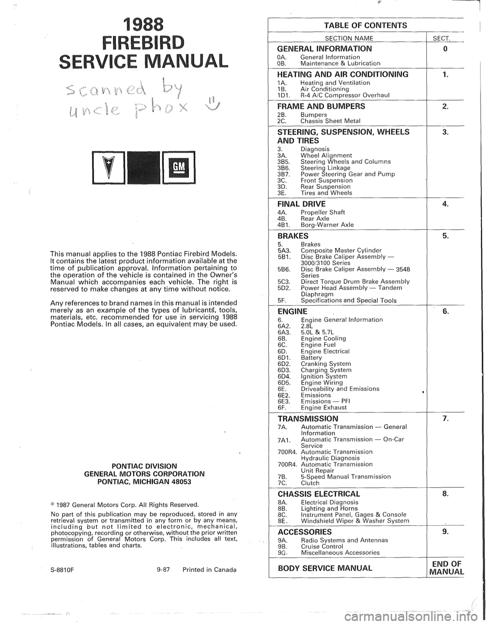
TABLE OF CONTENTS
SECTION NAME
GENERAL INFORMATION
OA. General lnformation
OB. Maintenance & Lubrication
1 SECT.
HEATING AND AIR CONDITIONING
1A. Heating and Ventilation
1 B. Air Conditioning
1D1. R-4 AIC Com~ressor Overhaul
FRAME AND BUMPERS
2B. Bumpers 2C. Chassis Sheet Metal
STEERING, SUSPENSION, WHEELS
AND TIRES
3. Diagnosis
3A. Wheel Alignment
3B5. Steering Wheels and Columns 3B6. Steering Linkage 3B7. Power Steering Gear and Pump
3C. Front Suspension
3D. Rear Suspension
3E. Tires and Wheels
FINAL DRIVE
4A. Propeller Shaft
4B. Rear Axle
4B1. Bora-Warner Axle
BRAKES 5. Brakes 5A3. Comoosite Master Cvlinder 5B1. Disc r rake Caliper ~ssembly - 300013100 Series 5B6. Disc Brake Caliper Assembly - 3548
Series
5C3. Direct Torque Drum Brake Assembly 5D2. Power Head Assembly - Tandem Diaohraam 5F. ~~ecifications and Special Tools
ENGINE 6. Engine General lnformation 6A2. 2.8L 6A3. 5.OL & 5.7L 6B. Engine Cooling
6C. En~ine Fuel
6D. ~ngine Electrical 6D1. Battery 6D2. Cranking System 6D3. Charging System 6D4. Ignition System 6D5. Engine Wiring
6E. Driveabilitv and Emissions
6E2. ~missions' 6E3. Emissions - PFI
6F. Engine Exhaust
TRANSMISSION 7A. Automatic Transmission - General
lnformation
7A1. Automatic Transmission - On-Car
Service
700R4. Automatic Transmission Hydraulic Diagnosis
700R4. Automatic Transmission Unit Repair
76. 5-Speed Manual Transmission
7C. Clutch
CHASSIS ELECTRICAL 8A. Electrical Diagnosis
8B. Lighting and Horns
8C. Instrument
Panel, Gages
& Console
8E. Windshield Wiper &Washer System
ACCESSORIES 9A. Radio Systems and Antennas 9B. Cruise Control 9G. Miscellaneous Accessories
I BODY SERVICE MANUAL END
OF
MANUAL
Page 4 of 1825
GENERAL INFORMATION OA-1
SECTION (DA
GENERAL NFORMAT
CONTENTS
................................... General Description OA- 1 Prevailing Torque Fasteners ......................... OA-2
...................................... Body Number Plate OA- 1 Recommendations For Fastener Reuse ........ OA-2
..................... Vehicle Identification Number OA- 1 Vehicle Lifting Procedures ............ ., ............. OA-2
......................................... Metric Fasteners OA- 1 Precautions Against Tipping ........................ OA-7
................... Fastener Strength Identification OA-2 Automotive Abbreviations ................... .... 0.4- 1 1
GENERAL DESCRIPTION
Only general information appears in this section. left
of the windshield, see Figure 2. Refer to Figure 3
Detailed specifications on major units are given at the for detailed "VIN" code information.
For Engine V.I.
end of each respective section of this manual. N. Location, refer to Figure
4.
BODY NUMBER PLATE METRIC FASTENERS
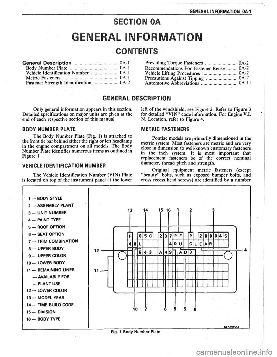
The Body Number Plate (Fig. 1) is attached to
Pontiac models are primarily dimensioned in the
the front tie bar behind either the right or left
headlamp metric system, Most fasteners are metric and are very in the engine On The close in dimension to well-known customary fasteners Number Plate identifies numerous items as outlined in in the inch system. It is most important that Figure 1. re~lacement fasteners be of the correct nominal
VEHICLE IDENTIFICATION NUMBER d&meter, thread pitch and strength.
Original equipment metric fasteners (except
The Vehicle Identification Number (VIN) Plate "beauty" bolts, such
as exposed bumper bolts, and
is located on top of the instrument panel at the lower cross
recess head screws) are identified by a number
1 -- BODY STYLE
2 ASSEMBLY PUNT
3 -- UNIT NUMBER
4 -- PAINT TYPE
5 - ROOF OPTION
6 -- SEAT OPTION
7 - TRIM COMBINATION
8 - UPPER BODY
9 - UPPER COLOR
10 -- LOWER BODY
11 - REMAINING LINES
- AVAILABLE FOR
--PLANT
USE
12 - LOWER COLOR
13 - MODEL YEAR
14 -- TIME BUILD CODE
15 - DIVISION
16 - BODY TvPE
6200224A
Fig. 1 Body Number Plate
Page 5 of 1825
OA-2 GENERAL INFORMATION
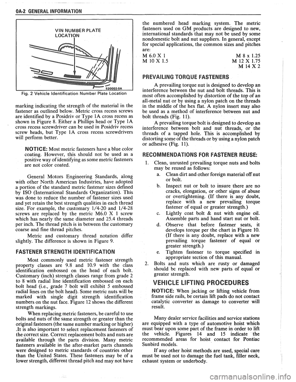
VIN NUMBER PLATE
LOCATION
Fig. 2 Vehicle Identification Number Plate Location
marking indicating the strength of the material in the
fastener as outlined below. Metric cross recess screws
are identified by a Posidriv or Type
1A cross recess as
shown in Figure 8. Either a Phillips head or Type
1A
cross recess screwdriver can be used in Posidriv recess
screw heads, but Type
1A cross recess screwdrivers
will perform better.
NOTICE: Most metric fasteners have a blue color
coating. However, this should not be used as a
positive way of identifying as some metric fasteners
are not color coated.
General Motors Engineering Standards, along
with other North American Industries, have adopted
a portion of the standard metric fastener sizes defined
by
IS0 (International Standards Organization). This
was done to reduce the number of fastener sizes used
and yet retain the best strength qualities in each thread
size. For example, the customary 1/4-20 and 1/4-28
screws are replaced by the metric
M6.0 X 1 screw
which has nearly the same diameter and
25.4 threads
per inch. The thread pitch is in between the customary
coarse and fine thread pitches.
Metric and customary thread notation differ
slightly. The difference is shown in Figure 9.
FASTENER STRENGTH ODENTIFIGATION
Most commonly used metric fastener strength
property classes are 9.8 and 10.9 with the class
identification embossed on the head of each bolt.
Customary (inch) strength classes range from grade 2
to 8 with radial line identification embossed on each
bolt head
(i.e., grade 7 bolt will exhibit 5 embossed
radial lines on the bolt head). Some metric nuts will be
marked with single digit strength identification
numbers on the nut face. Figure 12 shows the different
strength markings.
When replacing metric fasteners, be careful to use
bolts and nuts of the same strength or greater than the
original fasteners (the same number marking or higher)
.It is also important to select replacement fasteners of
the correct size. Correct replacement bolts and nuts are
available through the parts division. Many metric
fasteners available in the after-market parts channels
were designed to metric standards of countries other
than the United States. These fasteners may be of a
lower strength, different thread pitch and may not have the
numbered head marking system. The metric
fasteners used on GM products are designed to new,
international standards that may not be used by some
nondomestic bolt and nut suppliers. In general, except
for special applications, the common sizes and pitches
are:
M 6.0
X 1
M 8 x 1.25
M 10 X 1.5 M 12 X 1.75
M 14x2 I
PREVAILING TORQUE FASTENERS
A prevailing torque nut is designed to develop an
interference between the nut and bolt threads. This is
most often accomplished by distortion of the top of an
all-metal nut or by using a nylon patch on the threads
in the middle of the hex flat.
A nylon insert may also
be used as a method of interference between nut and
bolt threads (Fig. 11).
A prevailing torque bolt is designed to develop an
interference between bolt and nut threads, or the
threads of a tapped hole. This is accomplished by
distorting some of the threads or by using a nylon patch
or adhesive (Fig. 11).
RECOMMENDATIONS FOR FASTENER REUSE: I
Clean, unrusted prevailing torque nuts and bolts
may be reused as follows:
a. Clean dirt and other foreign material off nut
or bolt.
b. Inspect nut or bolt to insure there are no
cracks, elongation, or other signs of abuse
or overtightening. (If there is any doubt,
replace with a new prevailing torque
fastener of equal or greater strength.)
c. Lightly coat bolt
& nut with engine oil.
Assemble parts and hand start nut or bolt.
d. Observe that before fastener seats, it
develops torque per the chart in Figure
10.
(If there is any doubt, replace with a new
prevailing torque fastener of equal or
greater strength.)
e. Tighten fastener to torque specified in
appropriate section of this manual.
Bolts and nuts which are rusty or damaged
should be replaced with new parts of equal or
greater strength.
VEHICLE LIF"TING PROCEDURES
NOTICE: When jacking or lifting vehicle from
frame side rails, be certain lift pads do not contact
catalytic converter as damage to converter will
result.
Many dealer service facilities and service stations
are equipped with a type of automotive hoist which
must bear upon some part of the frame in order to lift
the vehicle. Figures 14 and 15 indicate the
recommended areas for hoist contact for Pontiac
Sunbird models.
If any other hoist methods are used, special care
must be used not to damage the fuel tank, filler neck,
I
exhaust system or underbody. I
Page 18 of 1825
MAINTENANCE AND LUBRICATION OB-1
SECTION OB
NTENANCE AND LUBR
CONTENTS
Maintenance Schedule, Gasoline .............................................. OB-l
Maintenance Schedules I and 11 .............................................. OB-2
Owner Inspections
......................................................... OB-3
Recommended Fluids and Lubricants ......................................... OB-6
PASSENGER CAR MAINTENANCE SCHEDULE
VEHICLES
WITH GASOLINE ENGINE
NORMAL CAR USE ITEM 4
The maintenance services contained in Schedules I Carburetor or Throttle Body Mounting Bolt
and 11 are based on the assumption that your car will be Torque* used as designed:
Check torque of mounting bolts and/or nuts. @ To carry passengers and cargo within the limits
shown on the Tire Placard located on the edge of the ITEM 5 driver's door.
@ On reasonable road surfaces within legal driving Engine Idle Speed Adjustment*
limits. (Engines
without Idle Speed Control or Idle Air
Control) - Adjust to specifications shown on the under- @ On unleaded gasoline.
hood label. If no specifications are shown on the label, no
adjustment is necessary. Calibrated test equipment must
EXPLANATION OF SCHEDULED MAINTENANCE be used. SERVICES
The services listed in Maintenance Scheduies I and ITEM 6
11 are further explained below. When the following main- ~i~~ and wheel aotation tenance services are performed, make sure all parts are
replaced and all necessary repairs are done before driving To equalize wear and obtain maximum tire life,
your car. Be sure to use the proper fluid and lubricants as rotate in accordance with patterns shown in Owner's
shown in Figure OB-2. Manual.
ITEM 1
Engine Oil and Oil Filter Change*
ALWAYS USE SFICC OR SF/CD ENERGY CON-
SERVING OILS OF PROPER VISCOSITY
- Also.
always change oil and filter as soon as possible after
driving in a dust storm. See your Owner's Manual for
further details.
ITEM 2
Chassis Lubrication
Lubricate all grease fittings in suspension and steer-
ing linkage. Lubricate
transmissionltransaxle shift
linkage, parking brake cable guides, underbody contact
points and linkage. Also lubricate clutch cross shaft lever
every
30,000 miles (50 000 km) on rear-wheel-drive cars
only.
ITEM 3
Carburetor Choke and Hoses*
If your car is equipped with a carburetor, verify that
choke and vacuum break work properly and are within
specifications. Correct any binding caused by damage or
gum on the choke shaft. Inspect hoses for proper hookup,
cracks, chafing or decay. Correct as necessary.
Vacuum or A.I.R. Pump Drive Belt Inspection*
When a separate belt is used to drive the vacuum or
A.I.R.
pump, inspect it for cracks, fraying, wear and
proper tension. Adjust or replace as needed.
ITEM 8
Cooling System Service*
Drain, flush and refill system with new coolant. See
your Owner's Manual
for further details.
ITEM 9
Wheel Bearing Repack (Rear-Wheel-Drive Cars
Only Except Corvette)
Clean and repack front wheel bearings at each brake
relining or 15,000 miles
(25 000 km), whichever comes
first, when car is used in such service as police, taxi or
door-to-door delivery. If you do not use your car in such
service, clean and repack bearings at each brake relining
or 30,000 miles
(50 000 km), whichever comes first.
Corvette models do not require wheel bearing repack.
Page 46 of 1825
AIR CONDITIONING 1 B-3
A low-side pressure Schrader valve service fit-
ting is located near the top of the accumulator. A
similar Schrader fitting may be provided for mounting
the pressure cycling switch. It is not necessary to dis-
charge the system to replace the switch. The accumu-
lator is serviced only as a replacement assembly.
Heater Core
The heater core heats the air before it enters the
car. Engine coolant is circulated through the core to
heat the outside air passing over the fins of the core.
The core is functional at all times (no water valve) and
may be used to temper conditioned air in
A/C mode,
as well as heat or vent mode.
SYSTEM COMPONENTS --- CON"FOL
Controller
The operation of the A/C system is controlled by
the switches and the lever on the control head. The
compressor clutch and blower are connected electri-
cally to the control head by a wiring harness. The
blower circuit is open in the off mode and air flow is
provided by the four blower speeds available in the
remaining modes. Cooled and dehumidified air is
available in the max, normal, bi-level and defrost
modes.
Temperature is controlled by the position of the
temperature lever on the control head. A cable con-
nects this lever to the temperature door which controls
air flow through the heater core. As the temperature
lever is moved through its range of travel, a sliding
clip on the cable at the temperature valve connection
should assume a position assuring that the temperature
door will seat in both extreme positions. Temperature
door position is independent of mode selection. The
temperature cable attaches to the right side of the air
conditioning module. The temperature door on some
models is controlled electrically, thereby eliminating
the need for the temperature cable.
The electric engine cooling fan on some cars is
not part of the
A/C system; however, the fan is
operational any time the
A/C control is in Max.,
Norm, or Bi-Level modes. Some models provide for
engine cooling fan operation when the controller is in
the defrost mode. This added feature is part of the
A/C
controller function and is aimed at preventing exces-
sive compressor head temperatures. It also allows the
A/C system to function more efficiently. On some
models during road speed (above
35 mph) conditions
when air flow through the condenser coil is adequate
for efficient cooling, the engine cooling fan will be
turned off. The operation of the cooling fan is con-
trolled by the ECM through the cooling fan relay.
Complete wiring diagrams and diagnosis for the
AIC Electrical System are in Section 8A. Section 8A
also contains additional diagnostic information
regarding air flows and vacuum logic.
Vacuum Lines
Vacuum lines are molded to a connector which
is attached to a vacuum control switch on the control
head assembly.
In case of leakage or hose collapse, it will not be
necessary to replace the entire harness assembly.
Replacement can be made by cutting the hose and
inserting a plastic connector. If an entire hose must be
replaced, cut all hoses off at the connector and then
attach hoses directly to the control head vacuum
switch. (NOTE: The Fiero uses an electric motor to
control mode selection. Therefore, it will not have a
vacuum harness.
)
Vacuum Tank
During heavy acceleration, the vacuum supply
from the carburetor drops. A check valve in the vac-
uum tank maintains vacuum so that, under load condi-
tions, vacuum will be available for continuous use.
REWVS AND SWITCHES
High-Pressure Compresssr Gut-OFF Switch
The high-side, high-pressure cut-off switch in
the rear head of the compressor is a protective device
intended to prevent excessive compressor head pres-
sures and reduce the chance of refrigerant escape
through a safety relief valve. Normally closed, this
switch will open the circuit at a high-side pressure of
approximately 2700
kPa (430 psi 9 20 psi) and
reclose the circuit at approximately 1379 kPa (200 psi
9 50 psi).
Lsw-Pressure Cut-On Switch
Compressor protection is provided on some cars
by a low-pressure cut-off switch which will open in
the event of a low-charge condition. This switch can
be located in the liquid line or in the rear head of the
compressor. This switch will also keep the compres-
sor from running during cold weather.
Pressure eyesing Switch
The refrigeration cycle (on and off operation of
the compressor) is controlled by a switch which
senses the low-side pressure as an indicator of evapo-
rator temperature. The pressure cycling switch is the
freeze protection device in the system and senses
refrigerant pressure on the suction side of the system.
This switch is located on a standard Schrader-type
valve low-side fitting. This switch also provides com-
pressor cut-off during cold weather.
Additional compressor protection results from
the operating characteristics of the low-side pressure
cycling system. If a massive discharge occurs or the
orifice tube becomes plugged, low-side pressures
could be insufficient to close the contacts of the pres-
sure switch. In the event of a low charge, insufficient
cooling accompanied by rapid compressor clutch
cycling will be noticed at high air temperatures.
Page 51 of 1825

1B-8 AIR CONDITIONING
INSUFFICIENT COQblNG "CHART A
A/C FUSE AND/OR GAGE FUSE.
OR DISCONNECTED
AlC WIRE CONNECTOR.
. CHECK BLOWER FOR FAN OPERATION.
. ENGINE COOLING FAN OPERATION (FAN OPERATES IN ALL A/C MODES AS FOLLOWS:
A. DISCONNECT ENGINE COOLANT TEMPERATURE FAN SWITCH.
8. WITH IGNITION ON AND ENGINE NOT RUNNING, SET A/C CONTROL TO A/C MODE.
C. ENGINE COOLING FAN SHOULD RUN.
D. RECONNECT ENGINE COOLANT TEMPERATURE FAN SWITCH.
REPLACE COMPRES-
SOR ASSEMBLY. RE-
PLACE ORIFICE. EVA-
CUATE AND CHARGE. AS
REQUIRED
AND 'HIGH' BLOWER.
T
AUXIL I ARY FAN IN T OF VEHICLE.
I OFF ALL THE TIME I
RESTRICTION IN HIGH
SIDE OF SYSTEM.
VISUALLY CHECK FOR
FROST SPOT TO LOCATE
RESTRICTION. REPAIR.
Figure
8 C.C.O.T. NC System Insufficient Cooling Diagnostic Procedure (1 of 4)
Page 55 of 1825
18-12 AIR CONDITIONING
ELEGTRICAWACUUM SYSTEM
DIAGNOSIS
When diagnosing problems in the electrical sys-
tems of the air conditioning system, consult section
8A.
LEAK TESTING THE REFRIGERANT
SYSTEM
Whenever a refrigerant leak is suspected in the
system or a service operation performed which results
in disturbing lines or connections, it is advisable to
test for leaks.
Liquid Leak Detectors
There are a number of locations (fittings,
valves, etc.) on the air conditioning system where a
liquid leak detector solution may be used to pinpoint
refrigerant leaks.
By applying test solution to the area in question
with the swab that is attached to the bottle cap, bub-
bles will form within seconds if there is a leak.
For restricted access areas, such as sections of
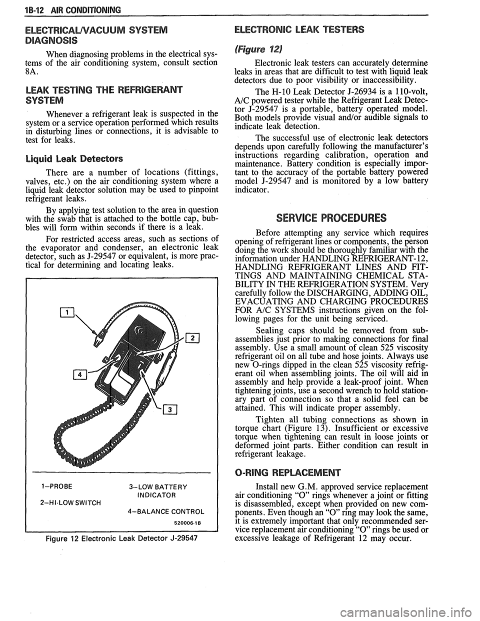
the evaporator and condenser, an electronic leak
detector, such as
5-29547 or equivalent, is more prac-
tical for determining and locating leaks.
3-LOW BATTERY
INDICATOR
2-HI-LOW SWITCH
4-BALANCE CONTROL
Figure 12 Electronic Leak Detector J-29547
ELECTRONIC LEAK TESTERS
(Figure 12)
Electronic leak testers can accurately determine
leaks in areas that are difficult to test with liquid leak
detectors due to poor visibility or inaccessibility.
The H-10 Leak Detector 5-26934 is a 110-volt,
A/C powered tester while the Refrigerant Leak Detec-
tor J-29547 is a portable, battery operated model.
Both models provide visual
and/or audible signals to
indicate leak detection.
The successful use of electronic leak detectors
depends upon carefully following the manufacturer's
instructions regarding calibration, operation and
maintenance. Battery condition is especially impor-
tant to the accuracy of the portable battery powered
model
5-29547 and is monitored by a low battery
indicator.
SERVICE PROCEDURES
Before attempting any service which requires
opening of refrigerant lines or components, the person
doing the work should be thoroughly familiar with the
information under HANDLING REFRIGERANT- 12,
HANDLING REFRIGERANT LINES AND FIT-
TINGS AND MAINTAINING CHEMICAL STA-
BILITY IN THE REFRIGERATION SYSTEM. Very
carefully follow the DISCHARGING, ADDING OIL,
EVACUATING AND CHARGING PROCEDURES
FOR
A/C SYSTEMS instructions given on the fol-
lowing pages for the unit being serviced.
Sealing caps should be removed from sub-
assemblies just prior to making connections for final
assembly. Use a small amount of clean 525 viscosity
refrigerant oil on all tube and hose joints. Always use
new O-rings dipped in the clean 525 viscosity refrig-
erant oil when assembling joints. The oil will aid in
assembly and help provide a leak-proof joint. When
tightening joints, use a second wrench to hold station-
ary part of connection so that
a solid feel can be
attained. This will indicate proper assembly.
Tighten all tubing connections as shown in
torque chart (Figure
13). Insufficient or excessive
torque when tightening can result in loose joints or
deformed joint parts. Either condition can result in
refrigerant leakage.
O-RING REPWCEMENT
Install new G. M. approved service replacement
air conditioning
"0" rings whenever a joint or fitting
is disassembled, except when provided on new com-
ponents. Even though an
"0" ring may look the same,
it is extremely important that only recommended ser-
vice replacement air conditioning
"0" rings be used or
excessive leakage of Refrigerant 12 may occur.
Page 58 of 1825
AIR GONDlTlONlNG 1B-15
involves opening the refrigeration system. Always
work in a well ventilated area and avoid breathing any
refrigerant fumes. If liquid refrigerant comes into con-
tact with the eyes, injury may result.
@ Before removing and replacing any of the air
conditioning refrigeration lines or components,
the system must be completely discharged of
Refrigerant- 12.
@ Always use service valve and pressure gauge
sets during evacuation and charging procedures.
@ Always discharge system at low-side service fit-
ting and perform the entire evacuate and charg-
ing procedure through the low-side service
fitting.
@ Do not connect high-pressure line or any line to
the high-side
service fitting during discharging
and charging procedures.
CAUTION: Never remove a gauge line
from its adapter when line is connected
to
AIC system. Always remove the line
adapter from the service
fining to dis-
connect a line. Do not remove charging
hose at gauge set while
anached to ser-
vice low-side
fining. This will result in
complete discharge of system due to
the depressed Schrader valve in
service
low-side fining and may cause personal
injury due to escaping Refrigerant-12.
Discharging the NG System
In replacing any of the air conditioning refriger-
ation components, the system must be completely dis-
charged of Refrigerant- 12.
ALWAYS DISCHARGE SYSTEM AT
LOW-SIDE SERVICE FITTING.
1. With ignition turned "OFF," remove protective
cap from LOW-SIDE service fitting (on most
models) on Accumulator and connect charging
station
J-23500-01 or equivalent gauge set. If
charging station J-23500-01 or equivalent is not
being used, discharge system by slowly con-
necting a gauge hose to low-side
sewice fitting
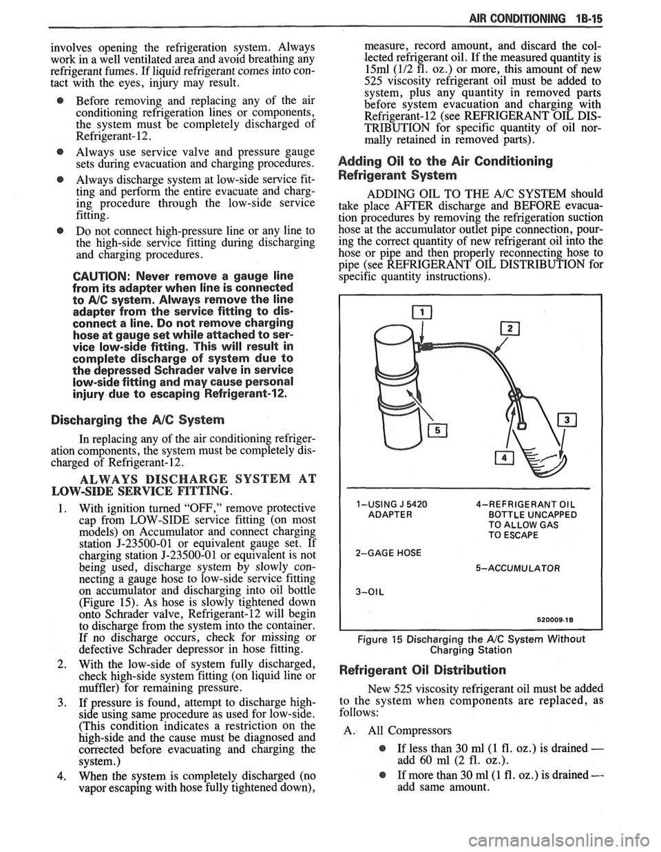
on accumulator and discharging into oil bottle
(Figure 15). As hose is slowly tightened down
onto Schrader valve, Refrigerant-12 will begin
to discharge from the system into the container.
If no discharge occurs, check for missing or
defective Schrader depressor in hose fitting.
2. With the low-side of system fully discharged,
check high-side system fitting (on liquid line or
muffler) for remaining pressure.
3. If pressure is found, attempt to discharge high-
side using same procedure as used for low-side.
(This condition indicates a restriction on the
high-side and the cause must be diagnosed and
corrected before evacuating and charging the
system.)
4. When the system is completely discharged (no
vapor escaping with hose fully tightened down), measure, record
amount, and discard the col-
lected refrigerant oil. If the measured quantity is
15ml (112 fl. 02.) or more, this amount of new
525 viscosity refrigerant oil must be added to system, plus any quantity in removed parts
before system evacuation and charging with
Refrigerant-12 (see REFRIGERANT OIL DIS-
TRIBUTION for specific quantity of oil nor-
mally retained in removed parts).
Adding Oil to the Air Conditioning
Refrigerant System
ADDING OIL TO THE A/C SYSTEM should
take place AFTER discharge and BEFORE evacua-
tion procedures by removing the refrigeration suction
hose at the accumulator outlet pipe connection, pour-
ing the correct quantity of new refrigerant oil into the
hose or pipe and then properly reconnecting hose to
pipe (see REFRIGERANT OIL DISTRIBUTION for
specific quantity instructions).
1-USING J 5420 4-REFRIGERANT OIL BOTTLE UNCAPPED
TO ALLOW GAS
TO ESCAPE
2-GAGE HOSE 5-ACCUMULATOR
Figure 15 Discharging the A/C System Without
Charging Station
Refrigerant Oil Distribution
New 525 viscosity refrigerant oil must be added
to the system when components are replaced, as
follows:
A. All Compressors
@ If less than 30 ml(1 fl. oz.) is drained -
add 60 ml (2 fl. oz.).
@ If more than 30 ml(1 fl. oz.) is drained --
add same amount.