1988 PONTIAC FIERO ECO mode
[x] Cancel search: ECO modePage 531 of 1825
6EZ-A-40 5.0L (WIN E) DRIVEABILITY AND EMISSIONS
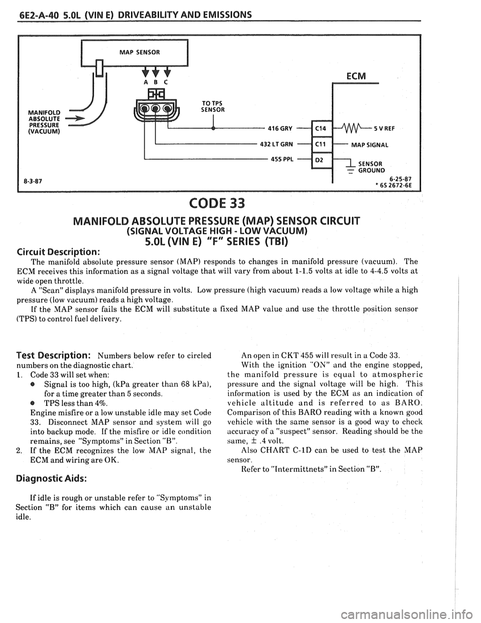
CODE 33
MANIFOLD ABSOLUTE PRESSURE (MAP) SENSOR CIRCUIT
(SIGNAL VOLTAGE HIGH - LOW VACUUM)
5.OL (VIN E) "F" SERIES (TBI)
Circuit Description:
The manifold absolute pressure sensor (MAP) responds to changes in manifold pressure (vacuum). The
ECM receives this information as a signal voltage that will vary from about
1-1.5 volts at idle to 4-4.5 volts at
wide open throttle.
A "Scan" displays manifold pressure in volts. Low pressure (high vacuum) reads
a low voltage while a high
pressure (low vacuum) reads a high voltage.
If the MAP sensor fails the ECM will substitute
a fixed MAP value and use the throttle position sensor
(TPS) to control fuel delivery.
Test Description: Numbers below refer to circled
numbers on the diagnostic chart.
1. Code 33 will set when:
@ Signal is too high, (kPa greater than 68 kPa),
for a time greater than 5 seconds.
-S TPS less than 4%.
Engine misfire or a low unstable idle may set Code
33. Disconnect MAP sensor and system will go
into backup mode. If the misfire or idle condition
remains, see "Symptoms" in Section "B".
2. If the ECM recognizes the low MAP signal, the
ECM and wiring are OK.
Diagnostic Aids:
An open in CKT 455 will result in a Code 33.
With the ignition "ON" and the engine stopped,
the manifold pressure is equal to atmospheric
pressure and the signal voltage will be high.
This
information is used by the ECM as an indication of
vehicle altitude
and is referred to as BARO.
Comparison of this
BARO reading with a known good
vehicle with the same sensor is a good way to check
accuracy of a "suspect" sensor. Reading should he the
same,
& .4 volt.
Also
CHART C-lD can be used to test the MAP
sensor.
Refer to
"Intermittnets" in Section "B".
If idle is rough or unstable refer to "Symptoms" in
Section
"B" for items which can cause an unstable
idle.
Page 552 of 1825
DRIVEABILITY AND EMISSIONS 5.OL (VIN E) 6E2-B-5
@ If the previous checks did not find the problem:
- Visually inspect ignition system for moisture,
dust, cracks, burns, etc. Spray plug wires with
fine water mist to check for shorts.
- Fuel System - Plugged fuel filter, water, low
pressure. See CHART A-7.
- Perform compression check.
- Valve timing.
- Remove rocker covers. Check for bent pushrods,
worn rocker arms, broken or weak valve springs,
worn camshaft lobes. Repair as necessary. See
Section
"6A".
If there is spray from only one injector, then,
there is
a malfunction in the injector assembly,
or in the signal to the injector assembly. The
malfunction can be isolated by switching the
injector connectors. If the problem remains with
the original injector, after switching the
connector, then the injector is defective. Replace
the iniector. If the
~roblem moves with the
injector connector, then, the problem is an
improper signal in the injector circuits. See
CHART A-3.
POOR FUEL ECONOMY
Definition: Fuel economy, as measured by an actual road test, is
noticeably lower than expected. Also, economy is noticeably lower than it
was on this car at one time, as previously shown by an actual road test.
@ CHECK: @ Visually (physically) check:
- Engine thermostat for faulty part (always open) - Vacuum hoses for splits, kinks, and proper
or for wrong heat range. See Section
"6B". connections, as shown on Vehicle Emission
- Fuel Pressure. See CHART A-7. Control Information label.
@ Check owner's driving habits. - Ignition wires for cracking, hardness, and proper
- Is A/C "ON" full time (Defroster mode "ON")? connections.
- Are tires at correct pressure? e Check ignition timing. See Emission Control
- Are excessively heavy loads being carried? Information label.
- Is acceleration too much, too often? @ Remove spark plugs. Check for cracks, wear,
- Suggest driver read "Important Facts on Fuel
improper gap, burned electrodes or heavy deposits.
Economy" in owner's manual. Repair
or replace, as necessary.
@ Perform "Diagnostic Circuit Check". @ Check compression. See Section "6A".
@ Check air cleaner element (filter) for dirt or @ Check TCC for proper operation. See CHART C-8.
being plugged. Use "Scan"
tool if available.
@ Check for proper calibration of speedometer. @ Check for dragging brakes.
Suggest owner fill fuel tank and recheck fuel
economy.
@ Check for exhaust system restriction. ,
See CHART B-1.
ROUGH, UNSTABLE, OR INCORRECT IDLE, STALLING
Definition: The engine runs unevenly at idle. If bad enough, the car may
shake. Also,
the idle may vary in rpm (called "hunting"). Either condition
may be severe enough to cause stalling. Engine idles at incorrect speed.
@ CHECK: - Vacuum leaks can cause higher than normal
- Ignition timing. See Emission Control idle.
Information label.
- EGR "ONJ', while idling, will cause roughness,
- PIN switch circuit. See CHART C-1 A. stalling, and hard starting. CHART C-7.
- For injectorb) leaking. Check fuel pressure, - Battery cables and ground straps should be clean ,
CHART A-7. and secure. Erratic voltage will cause IAC to
- IAC - See CHART C-2C.
change its position, resulting in poor idle quality.
- If a sticking throttle shaft or binding linkage - IAC valve will not move, if system voltage is
causes
a high TPS voltage (open throttle
below 9, or greater than 17.8 volts.
indication), the ECM will not control idle.
- Use "Scan" tool to determine if ECM is receiving
Monitor TPS voltage. "Scan"
andlor voltmeter AlC request signal.
should read less than
1.2 volts with throttle
closed.
Page 556 of 1825
DRIVEABILITY AND EMISSIONS 5.OL (VIN El 6EZ-C1-1
SECTION Cl
ELECTWONllC CONTROL MODULE (ECM) AND SENSORS
CONTENTS
GENERAL DESCRIPTION . . . . . . . . . . . . . . . C1-1 Coolant Temperature Sensor . . . . . . . . C1-5
ELECTRONIC CONTROL MODULE (ECM) . . C1-1 MAT Sensor. . . . . . . . . . . .. . . ... . . . . $1 -5
PROM ........................... C1-1 MAP Sensor. . . . . . . . . . . . . . . . . . . . . . C1 -6
CALPAK.........,................ C1-2 Oxygen (02) Sensor. . . . . . ... . . . a C1-6
ECM FUNCTION . . . , . . . . . . . . . . . . . . . . C1-2 Throttle Position Sensor (TPS) . . . . . . . . C1-6
INFORMATION SENSORS . . . . . . . . . . . . . C1-2 Vehicle Speed Sensor (VSS) . . . . . . . . . C1-6
Engine Coolant Temperature Sensor . . C1-2 PIN Switch. . . . . . . . . . . . . . . . . . . . . . . C1-6
MAP Sensor. . . . . . . . . . . . . . . . . . . . . . C1-2 (PSPS) . . . . . ... .. . . . ... . . .. .. . . . C1-6
MAT Sensor. . . . . . . . . . . . . . . . . . . . . . C1-3 AJC Request Signal . . . . . . . . . . . . . . . . C1-6
Oxygen (Oz) Sensor. . . . . . . . . .. . . . . . C1-3 Distributor Reference Signal . . . . . . . . . C1-6
Throttle Posit~on Sensor (TPS) . . . . . . . . C1-3 Knock Signal . . . . . . . . . . . . . . . . . . . C1-6
Knock Sensor . . . . . . . . . . . . . . . . . . . . C1-4 ON-CAR SERVICE . . . . . . . . . . . . . . . . . . . . . C1-6
Park Neutral Switch (Auto Only) . . . . . . C1-4 ELECTRONIC CONTROL MODULE . . . . . . . 61-6
Crank Signal . . . . . . , . . . . . . . . . . . . . . C1-4 PROM ........................... C1-7
A/C "On" Signal . . . , . . . . . . . . . . . . . . C1-4 Functional Check . . . . . . . . . . . . . . . . . C1-8
Vehicle Speed Sensor (VSS) . . . . . . . . . C1-4 CALPAK...................,...... C1-8
Distributor Reference Signal . . . . . . . . . C1-4 COOLANTSENSOR .. . . . . . . . , . . . . . . . . . C1-9
(PSPS) . . . . . . . . . . . . . . . . . . . . . . . . . C1-4 MAPSENSOR ..... ........ ... . .. . .* C1-9
DIAGNOSIS . . . . . . . . . . . . . . . . . . . . . . . . . C1-5 OXYGEN (02) SENSOR . . . . . . . . . a . . a . . C1-9
ECM ............................. C1-5 THROTTLE POSITION SENSOR (TPS) . . . . . C1-10
PROM ........................... C1-5 PARKINEUTRALSWITCH . . . . . . . . . . . . . . C1-10
ECM INPUTS.. . . . . . . . . . . . . . . . , . . . . . C1-5 PARTS
INFORMATION . . . . . . . . . . . . . . . . . C1-10
GENERAL DESCRIPTION
ELECTRONIC CONTROL MODULE (ECM)
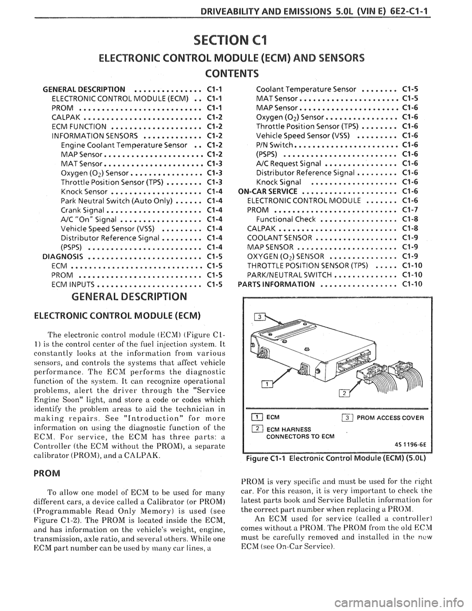
The electronic control module (KCMI (Figure C1-
1) is the control center of the fuel ir!jection system. It
constantly looks at the information from various
sensors, and controls the systems that affect vehicle
performance. The ECM performs the diagnostic
function of the system. It can recognize operational
problems, alert the driver through the "Service
Engine Soon" light, and store a code or codes which
identify the problem areas to aid the technician in
making repairs. See "Introduction" for more
information on using the diagnostic function of the
ECM. For service, the ECM has three parts:
a
Controller (the ECM without the PROM), a separate
calibrator (PROM), and a
CALPAK.
To allow one model of ECM to be used for many
different cars, a device called a Calibrator (or PROM)
(Programmable Read Only Memory) is used (see
Figure
C1-2). The PROM is located inside the ECM,
ancl has information on the vehicle's weight, engine,
transmission, axle ratio, and several others. While one
ECM part number can be used by many car lines, a
ECM PROM ACCESS COVER
1 ECM HARNESS
CONNECTORS TO ECM
45 1196-6E
Figure C1-1 Electronic Control Module (ECM) (5.OL)
PROM is very specific and must be used for the right
car. For this reason, it is very important to checlc the
latest parts book and Service Bulletin information for
the correct part number when replacing
a PROM.
An ECM used for service (called a controller)
comes without a
PROM. The PROM from the old blC>1
must be carefully removed and installctl in the new
EChI (see On-Car Service).
Page 576 of 1825
DRIVEABILIW AND EMISSIONS - 5.OL (VIN E) 6E2-62-1
SECTION C2
FUEL CONTROL SYSTEM
TBI MODEL 228
CONTENTS
GENERAL DESCRIPTION . . . . . . . . . . . . . . . C2-1
PURPOSE ......................... C2-1
MODES OF OPERATION . . . . . . . . . . . . . . C2-1
Starting Mode . . . . . . . . . . . . . . . . . . . C2-1
Clear Flood Mode . . . . . . . . . . . . . . . . C2-2
RunMode . . . . . . . . . . . . . . . . . . . . . . C2-2
Open Loop . . . . . . . . . . . . . . . . . . . . . . C2-2
Closed Loop . . . . . . . . . . . . . . . . . . . . . C2-2
Acceleration Mode . . . . . . . . . . . . . . . C2-2
Deceleration Mode . . . . . . . . . . . . . . . C2-2
Battery Correction Mode . . . . . . . . . . . C2-2
Fuel Cut Off Mode . . . . . . . . . . . . . . . . C2-2
FUEL CONTROL SYSTEM COMPONENTS
. . . C2-2
BASIC SYSTEM OPERATION . . . . . . . . . . . C2-3
THROTTLE BODY INJECTION (TBI) UNIT. . . C2-3
Fuel Injectors . . . . . . . . . . . . . . . . . . . . C2-3
Pressure Regulator . . . . . . . . . . . . . . . C2-3
ldle Air Control (IAC) Valve . . . . . . . . . . C2-4
Throttle Position Sensor (TPS) . . . . . . . . C2-4
FUEL PUMP.. . . . . . . . . . . . . . . . . . . . . . . C2-5
FUEL PUMP ELECTRICAL CIRCUIT . . . . . . . C2-5
DIAGNOSIS . . . . . . . . . . . . . . . . . . . . . . * C2-5
FUEL CONTROL . . . . . . . . . . . . . . . . . . . . C2-5
GENERAL DESCRIPTION
PURPOSE
The basic function of the fuel control system is to
control fuel delivery to the engine. Fuel is delivered to
the engine by
a throttle body injection ('FBI) unit.
ENGINE CONTROL MODULE (ECM)
EXHAUST OXYGEN (0,) SENSOR
I 1 THROTTLE BODY INJECTION UNIT (TBI)
CATALYTIC CONVERTER
8P 0352 SYE a 3 81
Figure C2-1 - Closed Loop System
ldle Air Control Valve (IAC) . . . . . . . . . C2-5
Driveability . . . . . . . . . . . . . . . . . . . .. C2-5
ON VEHICLE SERVICE
. . . . . . . . . . . . . . . . . C2-5
GENERAL SERVICE INFORMATION . . . . . . C2-5
Fuel Pressure Relief . . . . . . . . . . . . . . . C2-7
Fuel System Pressure Test . . . . . . . . . . . C2-7
Cleaning and Inspection . . . . . . . . . . . C2-7
Thread Locking Compound . . . . . . . . . C2-7
FUEL METER COVER ASSEMBLY . . . . . . . . C2-7
FUEL INJECTOR ASSEMBLIES . . . . . . . . . . C2-8
FUEL METER BODY ASSEMBLY . . . . . . . . . C2-9
THROTTLE POSITION SENSOR (TPS) . . . . . C2-10
IDLE AIR CONTROL (IAC) VALVE . . . . . . . . C2-11
THROTTLEBODYASSEMBLY .......... C2-11
MINIMUM IDLE SPEED CHECK.. . . . . . . . . C2-12
THROTTLE BODY INJECTION (TBI) UNIT.. . C2-I3
FUEL HOSEIPIPE ASSEMBLIES . . . . . . . . . . C2-13
Materials . . . . . . . . . . . . . . . . . . . . . . C2-13
Fuel Line Repair . . . . . . . . . . . . . . . . . . C2-13
FUEL PUMP RELAY . . . . . . . . . . . . . . . . . . C2-13
OIL PRESSURE SWITCH . . . . . . . . . . . . . . . C2-13
PARTS INFORMATION
. . . . . . . . . . . . . . . . . C2-14
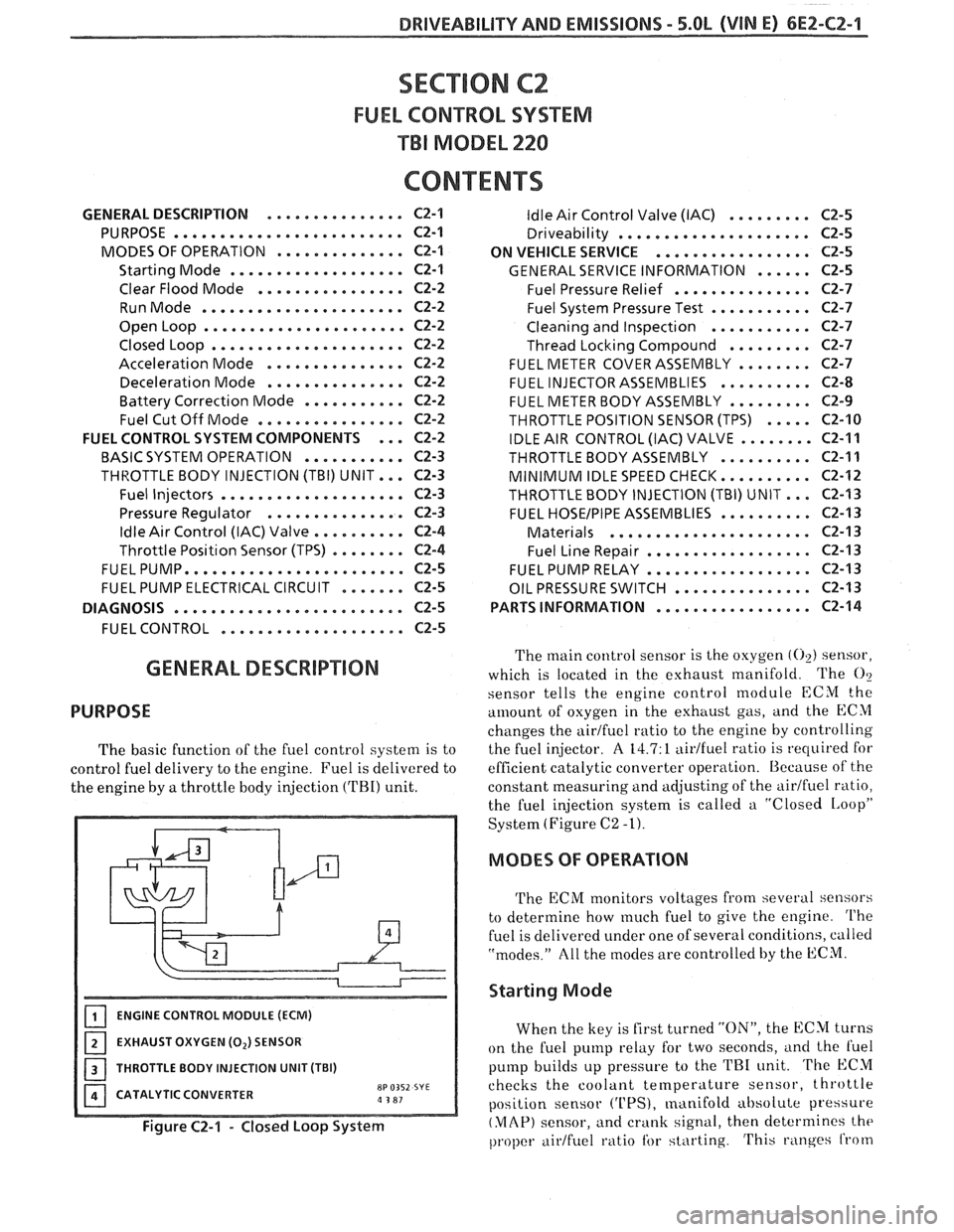
The main control sensor is the oxygen (02) sensor,
which is located in the exhaust manifold. The
O?
sensor tells
the engine control module ECM the
amount of osygen in the exhttust gas, and the ECM
changes the airtfuel ratio to the engine by controlling
the fuel injector.
A 14.7: 1 aidfuel ratio is required for
efficient catalytic converter operation. Because of the
constant measuring and adjusting of the
airlfuel ratio,
the fuel injection system is called a "Closed
IAoopP
System (Figure C2 -1).
MODES OF OPERATION
The ECM monitors voltages from several sensors
to determine how
much fuel to give the engine. The
fuel is delivered under one of several conditions, called
"modes." All the modes are controlled by the ECM.
Starting Mode
When the key is first turned "ON", the ECM turns
on the fuel pump relay for two seconds,
i~nd the l'uel
pump builds up pressure to the TRI unit. The ECM
checks the coolant
temperature sensor, throttle
position sensor
('UPS), manifold absolute pressure
(MAP) sensor, and crank signal, then determines the
proper airtfuel ratio tbr starting. This ranges from
Page 577 of 1825
6EZ-C2-2 DRIVEABILITY AND EMISSIONS - 5.8b (VIN E)
1.5:1 at -36°C (-33°F) to 14.7:1, at 94°C (201°F)
running temperature.
The ECM controls the amount of fuel delivered in
the starting mode by changing how long the injector is
turned "ON" and "OFF". This
is done by "pulsing" the
injector for very short times.
Clear Flood Mode
If the engine floods, clear it by pushing the
accelerator pedal down all the way. The ECM then
pulses the injector at a
20:1 airlfuel ratio, and holds
this injector rate as long as the throttle stays wide
open, and the engine is below 600 rpm. If the throttle
position becomes less than
80%, the ECM returns to
the starting mode.
Run Mode
The run mode has two conditions called "Open
Loop" and "Closed Loop."
Open Loop
When the engine is first started, and it is above
400 rpm, the system goes into "Open Loop" operation.
In "Open Loop," the ECM ignores the signal from the
(02) sensor, and calculates the airlfuel ratio based on
inputs from the coolant temperature and MAP
sensors.
The system stays in "Open Loop" until the
following conditions are met:
1. The
O2 sensor has varying voltage output,
showing that it is hot enough to operate properly.
(This depends on temperature.)
2. The coolant temperature sensor is above a
specified temperature.
3. A specific amount of time has elapsed after
starting the engine.
Closed Loop
The specific values for the above conditions vary
with different engines, and are stored in the
programmable read only memory (PROM). When
these conditions are met, the system goes into "Closed
Loop" operation. In "Closed Loop," the ECM
calculates the
aidfuel ratio (injector on-time) based on
the signal from the
O2 sensor. This allows the aidfuel
ratio to stay very close to 14.7:1.
Acceleration Mode
The ECM looks at rapid changes in throttle
position and manifold pressure, and provides extra
fuel.
Deceleration Mode
When deceleration occurs, the fuel remaining in
the intake manifold can cause excessive emissions and
backfiring. Again, the ECM looks at changes in
throttle position and manifold pressure and reduces
the amount of fuel. When deceleration is very fast, the
ECM can cut off fuel completely for short periods.
Battery Voltage Correction Mode
When battery voltage is low,
the ECM can
compensate for a wealc spark delivered by the
distributor by:
@ Increasing injector on time of fuel delivered;
@ Increasing the idle rpm.
Fuel Cutoff Mode
No fuel is delivered by the injectors when the
ignition is "OFFJ'. This prevents dieseling. Also, fuel
is not delivered if no reference pulses are seen from
the distributor, which means the engine is not
running.
Fuel cutoff also occurs at high engine
rpm, to protect internal engine components from
damage.
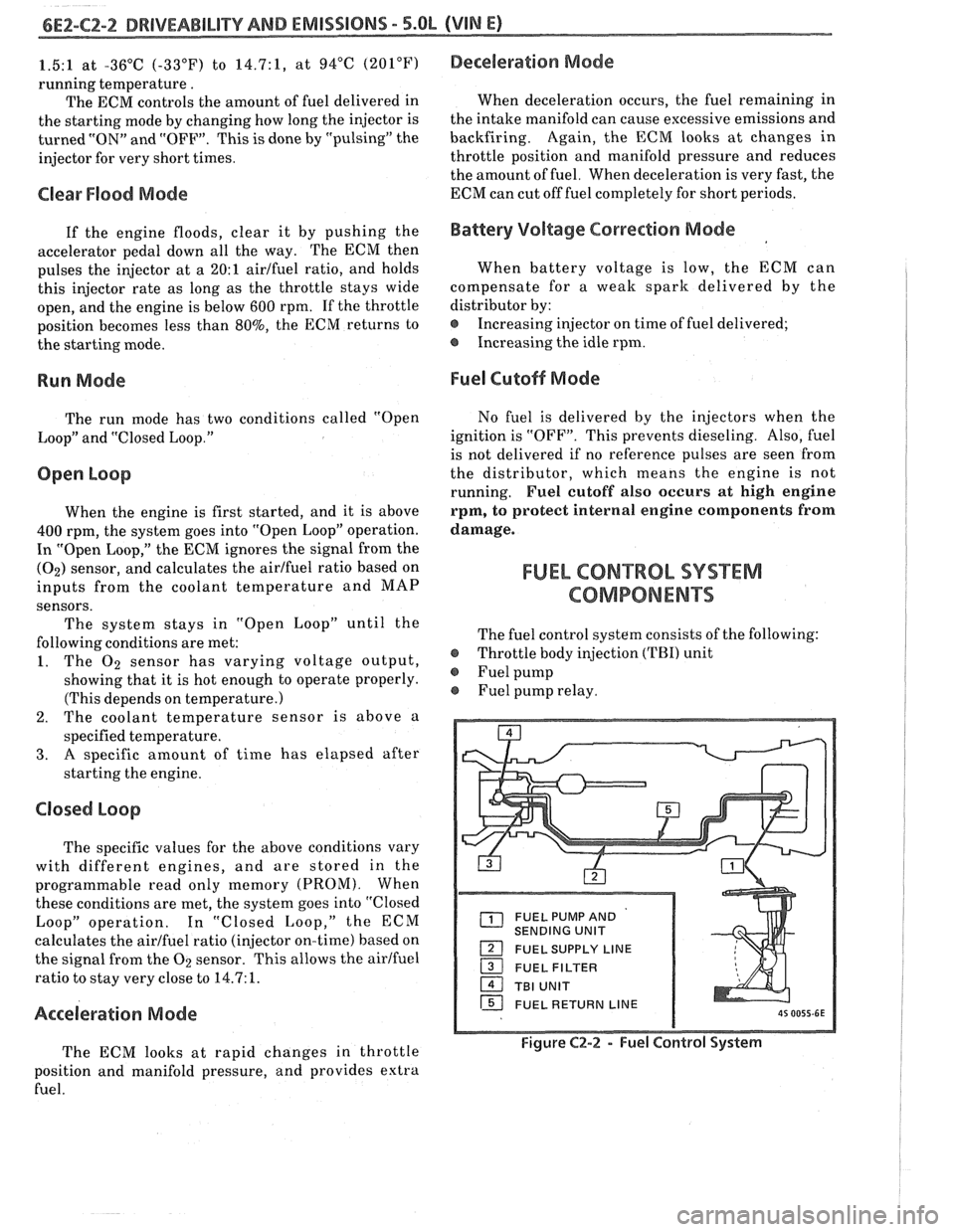
FUEL CON"%ROL SYSXM
COMPONENTS
The fuel control system consists of the following:
@ Throttle body injection (TBI) unit
@ Fuel pump
Fuel pump relay.
FUEL PUMP AND
SENDING UNIT
FUEL SUPPLY LINE
16 FUEL RETURN LINE
Figure C2-2 - Fuel Control System
Page 582 of 1825
DRIVEABILITY AND EMISSIONS - 5.BL (VIN E) 6E2-CZ-7
Refer to the disassembled view (Figure C2-8) for
identification of parts during repair procedures.
Service repair of individual components is performed
without removing the TBI unit from the engine. If
removed, it is essential that care is taken to prevent
damage to the throttle valve or sealing surface while
performing any service.
Whenever service is performed on the TBI or any
of its components, first remove the air cleaner, adapter
and air cleaner gaskets. Discard the gaskets and
replace them with new ones before replacing the air
cleaner after service is complete.
When disconnecting the fuel lines, be sure to use a
backup wrench
(J-29698-A, or BT8251-A, or
equivalent) to keep the TBI nuts from turning.
Fuel Pressure Relief
The TBI Model 220 on this engine contains a
constant bleed feature in the pressure regulator that
relieves pressure. Therefore, no special pressure relief
procedure is required.
Fuel System Pressure Pest
A fuel system pressure test is part of several of the
diagnostic charts and symptom checks. To perform
this test, follow this procedure:
1. Turn engine "OFF" to relieve fuel pressure.
2. Remove air cleaner and plug THERMAC vacuum
port on TBI.
3. Uncouple fuel supply flexible hose in engine
compartment. Install fuel pressure gage
J-29658AlBT8205 and adapter 29658A-85
between steel line and flexible hose.
4. Tighten gage in line to ensure no leaks occur
during testing.
5. Start car and observe fuel pressure reading. It
should be 62-90
kPa (9-13 psi); if not, refer to
CHART A-7.
6. Relieve fuel pressure.
7. Remove fuel pressure gage.
8. Reinstall fuel line.
9. Start car and check for fuel leaks.
10. Remove plug from vacuum port and install air
cleaner with new gasket.
Cleaning and inspection
All TBI component parts, with the exception of
those noted below, should be cleaned in a cold
immersion cleaner such as Carbon
X (X-55) or
equivalent.
NOTICE: The throttle position sensor ('I'PS), idle air
control
(IAC) valve, pressure regulator
diaphragm assembly, fuel injectors or other
components containing
rubber,should NOT be placed in a solvent
or cleaner bath. A chemical reaction will
cause these parts to swell, harden or
distort. Do not soak the throttle body with
the above parts attached. If the throttle
body assembly requires cleaning, soaking
time in the cleaner should be kept to a
minimum. Some models have hidden
throttle shaft dust seals that could lose
their effectiveness by extended soaking.
1. Clean all metal parts thoroughly and blow dry
with shop air. Be sure that all fuel and air
passages are free of dirt or burrs.
2. Inspect mating casting surfaces for damage that
could affect gasket sealing.
Thread Locking Compound
Service repair kits are supplied with a small vial
of thread locking compound with directions for use. If
material is not available, use Loctite 262, or
GM part
number 10522624, or equivalent.
NOTICE: Do not use a higher strength locking
compound than recommended, since to do
so could make removing the screw
extremely difficult, or result in damaging
the screw head.
FUEL METER COVER ASSEMBLY
Replacement (Figure
C2-9)
The fuel meter cover assembly contains the fuel
pressure regulator assembly. The regulator has been
adjusted at the factory and should only be serviced as
a complete preset assembly.
CAUTION: DO NOT remove the four screws
securing the pressure regulator to
the fuel meter cover. The fuel
pressure regulator includes a large
spring under heavy compression
which, if accidentally released,
could cause personal injury.
Disassembly might also result in a
fuel leak between the diaphragm
and the regulator container.
Remove or Disconnect
I. Electrical connectors to fuel injectors. (Squeeze
plastic tabs and pull straight up.)
2. Long
and short fuel meter cover screw assemblies.
3. Fuel meter cover assembly.
Page 613 of 1825
6EZ-C6-2 5.OL (VIN E) DRIVEABILITY AND EMISSIONS
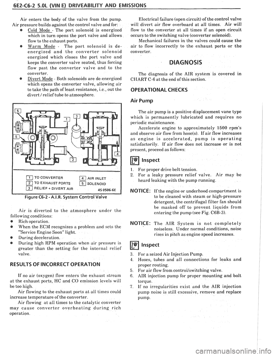
Air enters the body of the valve from the pump.
Air pressure builds against the control valve and for:
@ Cold Mode - The port solenoid is energized
which in turn opens the port valve and allows
flow to the exhaust ports.
@ Warm Mode - The port solenoid is de-
energized and the converter solenoid
energized which closes the port valve and
keeps the converter valve seated, thus forcing
flow past the converter valve and to the
converter.
@ Divert Mode - Both solenoids are de-energized
which opens the converter valve, allowing air
to take the path of least resistance,
i.e., out the
divert
/ relief tube to atmosphere.
TO CONVERTER AIR INLET
1 TO EXHAUST PORTS 1 SOLENOID / RELIEF + DIVERT AIR 45 0506-6E
Figure C6-2 - A.I.R. System Control Valve
Air is diverted to the atmosphere under the
following conditions:
@ Rich operation.
@ When the ECM recognizes a problem and sets the
"Service Engine Soon" light.
@ During deceleration.
During high RPM operation when air pressure is
greater than the setting for the internal relief
valve.
RESULTS OF lNCORRECP OPERATION
If no air (oxygen) flow enters the exhaust stream
at the exhaust ports, HC and CO emission levels will
be too high.
Air flowing to the exhaust ports at all times could
increase temperature of the converter.
Air flowing at all times to the catalytic converter
may cause converter overheating during rich
operation. Electrical failure
(open circuit) of the control valve
will divert air flow overboard at all times. Air will
flow to the converter at all times if an open circuit
occurs to the switching valve (converter solenoid).
Mechanical failures in the valves could cause the
air to flow incorrectly to the exhaust ports or the
converter.
DIAGNOSIS
The diagnosis of the AIR system is covered in
CHART C-6 at the end of this section.
OPERATIONAL CHECKS
Air Pump
The air pump is a positive displacement vane type
which is permanently lubricated and requires no
periodic maintenance.
Accelerate engine to approximately
1500 rpm's
and observe air flow from
hose(s). If air flow increases
as engine is accelerated, pump is operating
satisfactorily. If air flow does not increase or is not
present, proceed as follows:
a Inspect
1. For proper drive belt tension.
2. For a leaky pressure relief valve. Air may be
heard leaking with the pump running.
NOTICE: If the engine or underhood compartment is
to be cleaned with steam or high-pressure
detergent, the centrifugal filter fan should
be masked off to prevent liquids from
entering the pump (see Fig.
C6B-3).
NOTICE: The AIR System is not completely
noiseless. Under normal conditions, noise
rises in pitch as engine speed increases.
inspect
3. For a seized Air Injection Pump.
3. Hoses, tubes and all connections for leaks and
proper routing.
5. For air flow from control/switching valve.
6. AIR injection pump for proper mounting and bolt
torque.
7. If no irregularities exist and the AIR injection
pump noise is still excessive, remove and replace
pump.
Page 644 of 1825
INDEX
SECT ION PAGE
Diagnosis ......................... C1.5. 16
Service
........................... C1-8
MAT Sensor
General Description
.................. C1-2
Diagnosis
......................... C1-5
Service
........................... C1-7
Minimum
Idle Speed Adjustment ......... C2-14
Misses
.............................. B-4
Negative Backpressure Valve
............ C7-1
Non-Adjustable TPS Output Check
........ C2-14
Oil Pressure Switch
.................... C2-16
Oxygen Sensor
(02)
General Description ................. C1-3
Diagnosis ......................... C1-5
Service
........................... C1-9
Open Loop
.......................... C2-2
Park Neutral Switch
General Description
................. C1-4
Diagnosis
.......................... C1-5
C1-12
Service. Parts Information
............. C1-9
Poor Fuel Economy
.................... B.5.
C5- 1
Poor Performance
.................... C5-1
Positive Crankcase Ventilation (PCV)
General Description. Diagnosis
......... C13-1
Service. Parts Information
............. C13-2
Pressure Regulator
.................... C2-3
PROM General Description
................. C1-1
Diagnosis ......................... C1-5
Service
........................... C1-6
....................... Quad Drivers. C1-4
Reference Signal
...................... C1-5
Rough
Idle .......................... B-5
RunMode ........................... C2-2
SECTION PAGE
S
Sag ................................ B-4
"Scan" Data
......................... A-8
Sensor Information
.................... C1-2-9
Setting Timing
....................... C4-2
Shift Light
........................... C8-8
Sluggish
............................ B-3
Spark Knock
......................... B-4
Spongy
............................. 8-3
Stalling ............................. B-5
Starting Mode
........................ C2-1
Stumble
............................ B-4
Surges
............................. B-3
Table Of Contents
.................... A-1
Tank Pressure Control Valve
General Description
................. C3-2
Diagnosis
......................... C3-3
Throttle Body Injection Unit
General Description
................. C2-3
Service
........................... C2-7
C2- 14
Throttle Position Sensor
................ C2-5
General Description
................. C1-3
Diagnosis
......................... C1-5
Service
........................... C1-9
C2- 12
Transmission Converter Clutch TCC System
General Description
................. C8-1
Diagnosis
......................... C8-2
C8-4 C8-6
Parts Information
................... C8-2
Unstable
Idle ........................ B-5
....................... Vapor Canister C3-1
Vehicle Speed Sensor (VSS)
.................. General Description C1-4
Diagnosis
......................... 4.5
..................... Wiring Diagrams 8-3