1988 PONTIAC FIERO ECO mode
[x] Cancel search: ECO modePage 1186 of 1825
TROUBLESHOOTING TESTS m r rn 0
With a Short Finder
1. Remove the blown fuse, leaving the Battery
connected.
2. Connect the Short Finder across the fuse
terminals.
3. Close all switches in series with the circuit
you are troubleshooting.
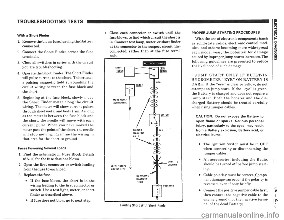
4. Operate the Short Finder. The Short Finder
will pulse current to the short. This creates
a pulsing magnetic field surrounding the
circuit wiring between the fuse block and
the short.
5. Beginning at the fuse block. slowly move
the Short Finder meter along the circuit
wiring. The meter will show current pulses
through sheet
inetal and body trim. As long
as the meter is between the fuse block and
the short, the needle will move with each
current pulse. When you have
moved the
meter past the point of the short. the needle
will stop
moving. Examine the wiring in
that area for the short to ground.
Fuses Powering Several Loads
1. Find the schematic in Fuse Block Details
(8A-11) for the fuse that has blown.
2. Open the first connector or switch leading
from the fuse to each load.
3. Replace the fuse.
@ If the fuse blows, the short is in the
wiring leading to the first connector or
switch. Use a test light, meter, or short
finder as described above.
@ If fuse does not blow, go to next step.
4. Close each connector or switch until the PROPER JUMP STARTING PROCEDURES
fuse blows, to find which circuit the short is
With the use of electronic components (such
in. Connect test lamp, meter, or short finder
as solid-state radios, electronic control
mod- at the connector to the suspect circuit (dis- ules, and others) becoming more wide-spread
connected) rather than at the fuse termi- each model year, the potential for damage nals. caused by improper jump starts increases. The
SHORT FUSE FINDER - BLOCK -
MOVE METER
NEEDLE STOPS
MOVING HERE
NO PULSING
MAGNETIC
FIELD
Cb
SHORT TO
GROUND
w-
Finding Short With Short Finder
following guidelines are presented to reduce
the likelihood of such damage.
JUMP START ONLY IF BUILT-IN
HYDROMETER "EYE" ON BATTERY IS
DARK. If the "eye" is clear or yellow, do not
attempt to jump start. If the "eye" is green,
the Battery is charged and does not require a
jump start. Both the booster and the dis-
charged Battery should be treated carefully
when using jumper cables.
CAUTION: Do not expose the Battery to
open flame or sparks. Serious personal
injury, particularly
to the eyes, may result
from
a Battery explosion, Battery acid, or
electrical burns.
The Ignition Switch must be in OFF
when connecting or disconnecting the
jumper cables.
All accessories. including the Radio.
should be turned off before jump start-
ing.
Cable polarity must be correct. Compo-
nent damage can occur
if the polarity is
re~~ersed. even if only briefly.
a Connect the positive jumper cable first.
then connect the negative cable to the
engine ground (not the negative termi-
nal of the dead Battery).
Page 1359 of 1825
AIR CONDITIONING: COMPRESSOR CONTROLS OD D
C60. MANUAL I I
(Continued from previous page) COMPONENT LOCATION
.......................... $177. Engine harness,
top RN front of engine ........ 201- 5-A
.......................... $204. I/P harness, behind instrument cluster. ........ 201-10-A
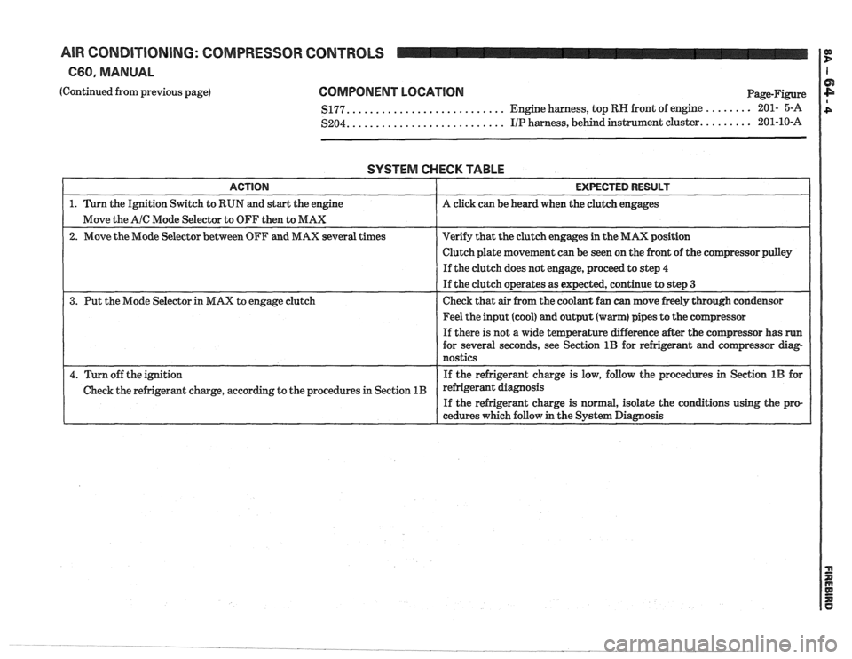
SYSTEM CHECK TABLE
I ACTION I EXPECTED RESULT I
1. Turn the Ignition Switch to RUN and start the engine A click can be heard when the clutch engages
Move the
A/C Mode Selector to OFF then to MAX
2. Move the Mode Selector between OFF and MAX several times Verify
that the clutch engages in the MAX position
I I Clutch plate movement can be seen on the front of the comgressor pdey I
I I If the clutch does not engage, proceed to step 4
If the clutch operates as expected, continue to step
3
3.
Put the Mode Selector in MAX to engage clutch Check
that air from the coolant fan can move freely through condensor
1 1 Feel the input (cool) and output (warm) pipes to the cornpressor I
I
If there is not a wide temperature difference after the compressor has run
for several seconds, see Section 1B for refrigerant and compressor diag-
nostics
4. Turn off the ignition If the
refrigerant charge is low, follow the procedures in Section 1B for
Check the refrigerant charge, according to the procedures in Section
1B refrigerant diagnosis
If the refrigerant charge is normal, isolate the conations using the pro-
cedures which follow in the System Diagnosis
Page 1362 of 1825
AIR CONDITIONING: COMPRESSOR
660, MANUAL
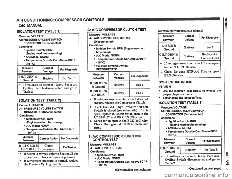
ISOLATION TEST (TABLE 1)
Measure: VOLTAGE
At: PRESSURE CYCLING
SWITCH
CONNECTOR (Disconnected)
Conditions: lgnition Switch: RUN
(Engine need not be running)
0 AIC Mode: NORM
Temperantre Outside Car: Above 60" F
(16" C)
Measure
Between Correct For Diagnosis /
I ILT Ground GRN'8rl Battery I Do Test B I
. If voltage is correct, leave Pressure
Cycling Switch disconnected and go to
Table
2.
ISOLATION TEST (TABLE 2)
Connect: JUMPER
At: PRESSURE CYCLING SWITCH
CONNECTOR (Disconnected)
Conditions: lgnition Switch: RUN
(Engine need not be running)
@ AIC Mode: NORM
0 Temperature Outside Car: Above 60" F
(16" C) I
Jumper I Correct Ac~on 1 For Diagnosis I I Between
If action is correct, refer to Section 1B for I
B (LT GRN) &
A (LT BLU)
I procedure to check refrigerant pressure. I
If refrigerant pressure is normal, replace
the Pressure Cycling Switch.
Clutch
engages
CONTROLS
Do Test A
A: Pale COMPRESSOR CLUTCH TEST
Measure: VOLTAGE
At:
A/C COMPRESSOR CLUTCH
(Disconnected)
Conditions:
0 Ignition Switch: RUN (Engine need not
be running)
0 AIC Mode: NORM
Temperature Outside Car: Above 60
OF
(16°C)
. Pressure Cycling Switch:
RECONNECTED
I
I ':"A':,",":' 1 ~attery I See 2 I
If voltages are correct but clutch does not
engage, replace the Compressor Clutch.
1. Check that AIC High Pressure Cut-Out
Switch is closed (see schematic). If
it is
open, replace it. Check for
an open in the
LT BLU
(67) and DK GRN (59) wires.
2. Check for an open in the BLK (150) wire.
Check that ground 6112 is clean and
tight.
B: AIC COMPRESSOR FUNCTION
CONTROL TEST
Measure: VOLTAGE
At: AIC CONTROL HEAD
Conditions: lgnition Switch: RUN
A/C Mode: NORM
0 Temperature Outside Car: Above 60" F
(16" C)
(Continued in next colum)
(Continued from previous column)
Measure Correct For Diagnosis
Between Voltage
Battery 1 See 1
Replace Ale
Control Head
If voltages are correct, check for an open
in the LT GRN
(66) wire.
1. Check for open HTR-AIC Fuse or open
BRN (50) wire.
SYSTEM DlAGlUOSlS
V8 VlN H
0 Use the isolation Test below to choose the
proper diagnostic tests.
Tests follow the Isolation Test.
lSOLATlOlU TEST (TABLE 1)
At: PRESSURE CYCLING SWITCH
CONNECTOR (Disconnected)
Ignition Switch: RUN
(Engine need not be running)
. A/C Mode: NORM
ramre Outside Car: Above 60 OF
Measure
I Between Correct I For Diagnosis I
Battery I Do Test B I I I
. If voltage is correct, leave Pressure
1 Cycling switch disconnected and go to I
(Continued on next page)
Page 1381 of 1825
AIR CONDITIONING: COMPRESSOR CONTROLS
667, ELECTRONIC:
(Continued from previous page)
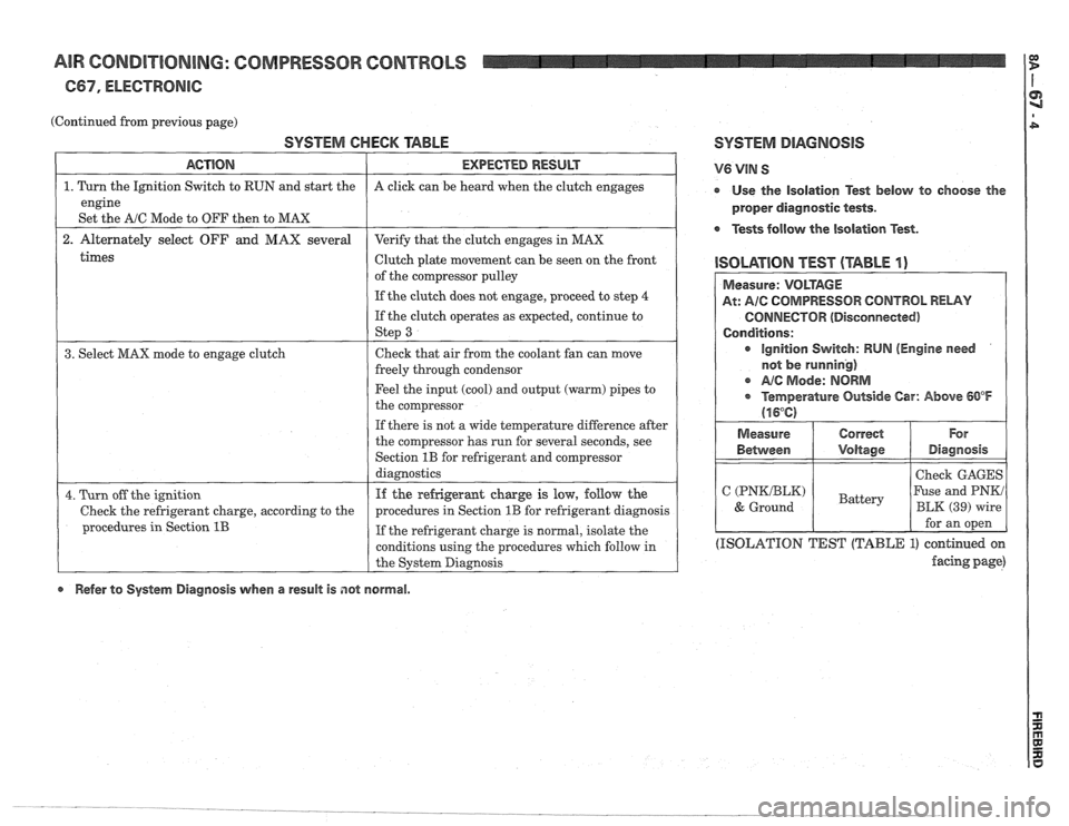
SYSTEM CHECK TABLE SYSTEM DIAGNOSIS
times
ACTION
1. Turn the Ignition Switch to RUN and start the
engine
Set the
A/C Mode to OFF then to MAX
2. Alternately select OFF and MAX several
Clutch plate movement can be seen on the front
1 ISOLATION TEST (TABLE I) of the compressor pulley
1 I If the clutch does not engage, proceed to step 4 (
EXPECTED RESULT
A click can be heard when the clutch engages
Verify that the clutch engages in MAX
If the clutch operates as expected, continue to
1 St€??J 3 I
V6 VIN S
r Use the isolation Test below to choose the
proper diagnostic tests.
Tests follow the isolation Test.
3. Select MAX mode to engage clutch Check
that air from the coolant fan can move
freely through condensor
Feel the input (cool) and output (warm) pipes to
the compressor
If there is not a wide temperature difference after
the compressor has run for several seconds, see
Section
1B for refrigerant and Compressor
diagnostics
4. Turn off the ignition
Check the refrigerant charge, according to the
procedures in Section
1B
If the refrigeramt charge is low, follow the
procedures in Section
1B for refrigerant diagnosis
If the refrigerant charge is normal, isolate the
conditions using the procedures which follow in
the System Diagnosis
(ISOLATION TEST (TABLE 1) continued on
facing page)
Measure: VOLTAGE
At: AIC COMPRESSOR CONTROL RELAY
CONNECTOR (Disconnected)
Conditions:
ignition Switch: RUN (Engine need
not
be running)
c A/@ Mode: NORM
* Temperature Outside Car: Above 60°F
(16°C)
Refer to System Diagnosis when a result is not normal. Measure
Between
C (PNKIBLK)
& Ground
Correct
Voltage
Battery
For
Diagnosis
Check GAGES
Fuse and PNKi
BLK (39) wire
for an open
Page 1386 of 1825
AIR CONDITIONING: COMPRESSOR CONTROLS
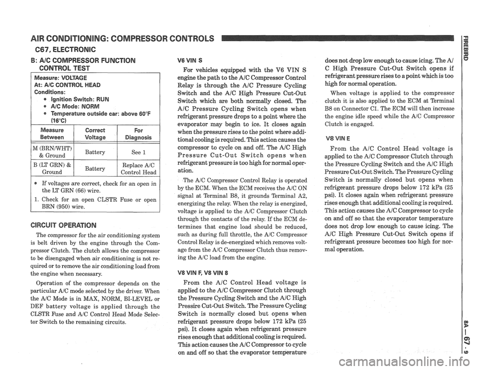
B: AIG COMPRESSOR FUNGTlON
CONTROL TEST
Measure: VOLTAGE
At: AIG CONTROL HEAD
Conditions:
e Ignition Switch: RUN
@ A/C Mode: NORM
@ Temperature outside car: above 60°F
(16°C)
1 Measure I Correct 1 For 1
Between I Voltage I Diagnosis I
1 ) 1 Battery 1 See 1 I
r If voltages are correct, check for an open in
the LT
GRN (66) wire.
B (LT GRN) &.
Ground
1. Check for an open CLSTR Fuse or open
BRN
(950) wire.
The compressor for the air conditioning system
is belt driven by the engine through the Com-
pressor Clutch. The clutch allows the compressor
to be disengaged when air conditioning is not re-
Battery
quired or to remove the air conditioning load from
the engine when necessary. Replace
A/C
Control Head
Operation of the compressor depends on the
particular A/C mode selected by the driver. When
the
A/C Mode is in MAX, NORM, BI-LEVEL or
DEF battery voltage is applied through the
CLSTR Fuse and
A/C Control Head Mode Selec-
tor Switch to the remaining circuits.
V6 VIN S
For vehicles equipped with the V6 VIN S
engine the path to the
A/C Compressor Control
Relay is through the
AlC Pressure Cycling
Switch and the
A16 Nigh Pressure Cut-Out
Switch which are both normally closed. The
Ale Pressure Cycling Switch opens when
refrigerant pressure drops to a point where the
evaporator may begin to ice.
It closes again
when the pressure rises to the point where
addi-
tional cooling is required. This action causes the
compressor to cycle on and off. The
Ale High
Pressure Cut-Out Switch opens when
refrigerant pressure is too high for
nomd oopr-
ation.
The AIC Compressor Control Relay is operated
by the EGM. When the ECM receives the
A/C ON
signal at Terminal
B8, it grounds Terminal A2,
energizing the relay. When the relay is energized,
voltage is applied to the
A/C Compressor Clutch
through the contacts of the relay. If the ECM de-
termines that engine load should be reduced,
such as during full throttle, the
A/C Compressor
Control Relay is de-energized which removes volt-
age from the
A/C Compressor Clutch thus remov-
ing the
A/C load from the engine.
V8 VlN F, V8 VllU 8
From the AlC Control Head voltage is
applied to the
A/@ Cornpressor Clutch through
the Pressure Cycling Switch and the
A/@ High
Pressire Cut-Out Switch. The Pressure Cycling
Switch is normally closed but opens when
refrigerant pressure drops below
172 kPa (25
psi). It closes again when refrigerant pressure
rises enough that additional cooling is required.
This action causes the
A/C Compressor to cycle
on and off so that the evaporator temperature does
not drop low enough to cause icing. The
A/
C High Pressure Cut-Out Switch opens if
refrigerant pressure rises to a point which is too
high for normal operation.
When voltage is applied to the compressor
clutch it is also applied to the ECM at
Terminal
B8 on Connector 61. The ECM will then increase
the engine idle speed while the
A/G Compressor
Clutch is engaged.
From the
AlC Control Head voltage is
applied to the
A/C Compressor Clutch though
the Pressure Cycling Switch and the AIC High
Pressure Cut-Out Switch. The Pressure
Cychg
Switch is normally closed but opens when
refrigerant pressure
drops below 172 kPa (25
psi). It closes again when refrigerant pressure
rises enough that
additional cooling is required.
This action causes the
A/C Compressor to cyde
on and off so that the evaporator teqerature
does not drop low enough to cause icing. The
A/C High Pressure Cut-Out Switch opens if
refrigerant pressure becomes too high for nor-
mal operation.
Page 1447 of 1825
WIPERIWASHER: PULSE, CB4
(Continued from previous page)
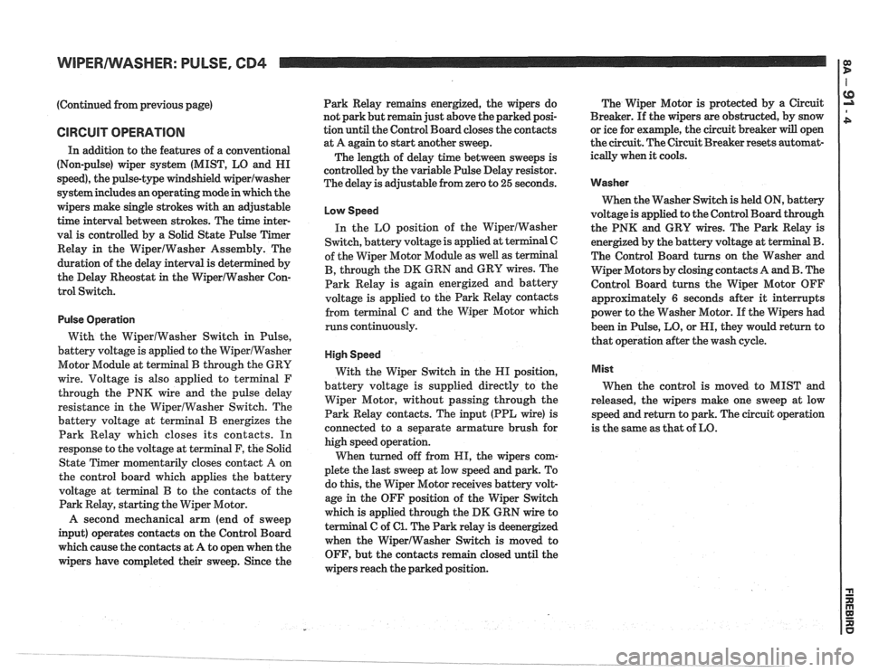
CIRCUIT OPERATION
In addition to the features of a conventional
(Non-pulse) wiper system (MIST, LO and HI
speed), the pulse-type windshield
wiperlwasher
system includes an operating mode in which the
wipers make single strokes with an adjustable
time interval between strokes. The time inter-
val is controlled by a Solid State Pulse Timer
Relay in the WiperIWasher Assembly. The
duration of the delay interval is determined by
the Delay Rheostat
in the WiperIWasher Con-
trol Switch.
Pulse Operation
With the WiperlWasher Switch in Pulse,
battery voltage is applied to the WiperlWasher
Motor Module at terminal
B through the GRY
wire. Voltage is also applied to
terminal F
through the PNK wire and the pulse delay
resistance in the WiperlWasher Switch. The
battery voltage at terminal
B energizes the
Park Relay which closes its contacts. In
response to the voltage at terminal F, the Solid
State Timer momentarily closes contact
A on
the control board which applies the battery
voltage at terminal
B to the contacts of the
Park Relay, starting the Wiper Motor.
A second mechanical arm (end of sweep
input) operates contacts on the Control Board
which cause the contacts at A to open when the
wipers have completed their sweep. Since the Park
Relay remains energized, the wipers do
not park but remain just above the parked posi-
tion until the Control Board closes the contacts
at A again to start
another sweep.
The length of delay time between sweeps is
controlled by the variable Pulse Delay resistor.
The delay is adjustable from zero to
25 seconds.
Low Speed
In the LO position of the WiperIWasher
Switch, battery voltage is applied at terminal C
of the Wiper Motor Module as well as terminal
B, through the DK GRN and GRY wires. The
Park Relay is again energized and battery
voltage is applied to the Park Relay contacts
from terminal
G and the Wiper Motor which
runs continuously.
High Speed
With the Wiper Switch in the HI position,
battery voltage is supplied directly to the
Wiper Motor, without passing through the
Park Relay contacts. The input (PPL wire) is
connected to a separate armature brush for
high speed operation.
When turned off from HI, the wipers com-
plete the last sweep at low speed and park. To
do this, the Wiper Motor receives battery volt-
age
in the OFF position of the Wiper Switch
which is applied through the
DM GRN wire to
terminal C of
61. The Park relay is deenergized
when the WiperlWasher Switch
is moved to
OFF, but the contacts remain closed until the
wipers reach the parked position. The
Wiper Motor is protected by a Circuit
Breaker. If the wipers are obstructed, by snow
or ice for example, the circuit breaker
will open
the circuit. The Circuit Breaker resets automat-
ically when
it cools.
Washer
When the Washer Switch is held ON, battery
voltage is applied to the Control Board through
the PNK and GRY wires. The Park Relay is
energized by the battery voltage at ter
The Control Board turns on the Washer and
Wiper Motors by closing contacts A and
B. The
Control Board turns the Wiper Motor OFF
approximately
6 seconds after it interrupts
power to the Washer Motor. If the Wipers had
been in Pulse, LO, or HI, they would return to
that operation after the wash cycle.
Mist
When the control is moved to MIST and
released, the wipers make one sweep at low
speed and return to park. The circuit operation
is the same as that of LO.
Page 1513 of 1825
THEFT DETERRENT SYSTEM: PASSKEY
(Continued from previous page)
If engine does not
Remove hush panel
disconnect C228
( Two-cavity
connector at base of
steering column)
Attempt to
start Engine should not
engine
Reconnect C228 and
attempt to start
engine again (must
be done within two
minutes of first
attempt)
Turn Ignition
Switch to
OFF
Wait four minutes
and turn Ignition
Switch to START crank
If engine cranks, do
Starter Enable
Relay Test
in
System Diagnosis
Engine should not
crank If engine cranks,
replace PASSKEY
I Decoder Module
I Replace hush panel 1 I
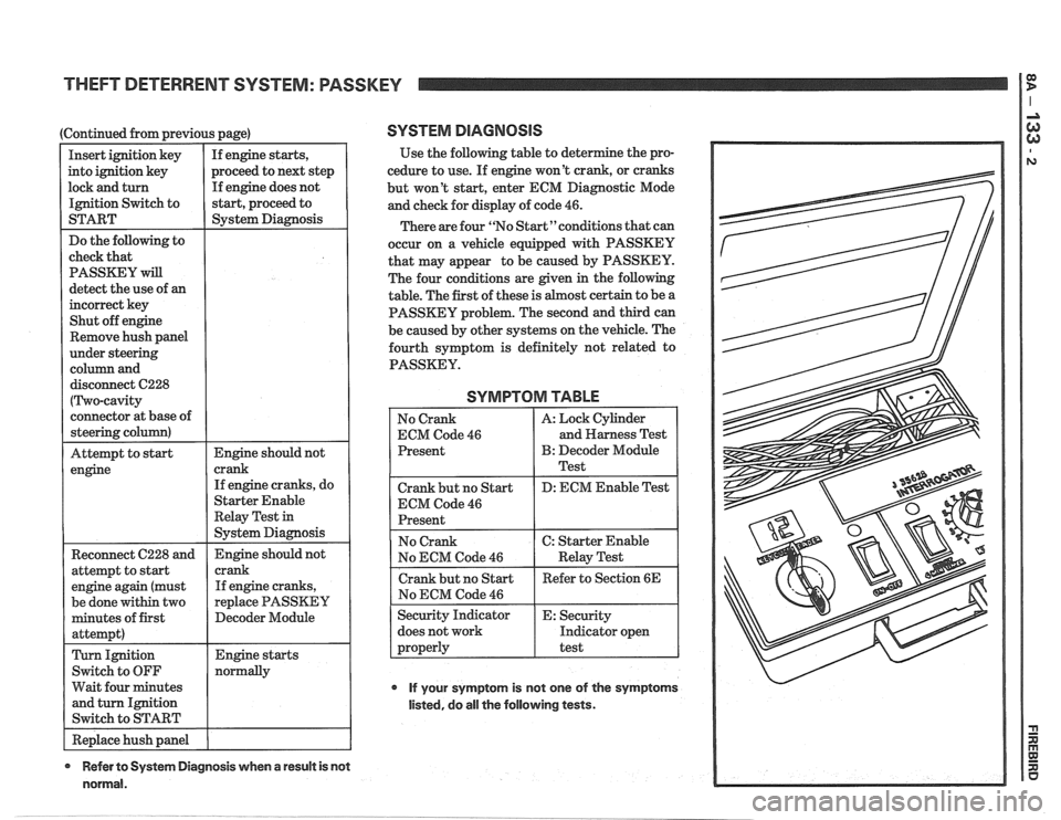
SYSTEM DIAGNOSIS
Use the following table to deter
cedure to use. If engine won't crank, or cranks
but won't start, enter ECM Diagnostic Mode
and check for display of code
46.
There are four "No Start"conditions that can
occur on a vehicle equipped with PASSKEY
that may appear to be caused by PASSKEY.
The four conditions are given in the following
table. The first of these is
host certain to be a
PASSKEY problem. The second and third can
be caused by other systems on the vehicle. The
fourth symptom is definitely not related to
PASSKEY.
SYMPTOM TABLE
No Crank
ECM Code
46
Present
Crank but no Start
ECM Code
46
Present A:
Lock Cylinder
and Harness Test
B: Decoder Module
Test
D: ECM Enable Test
No ECM Code
46
does not work Indicator open
If your symptom is not one of the symptoms
listed, do all the following tests.
* Refer to System Diagnosis when a result is not
normal.
Page 1556 of 1825
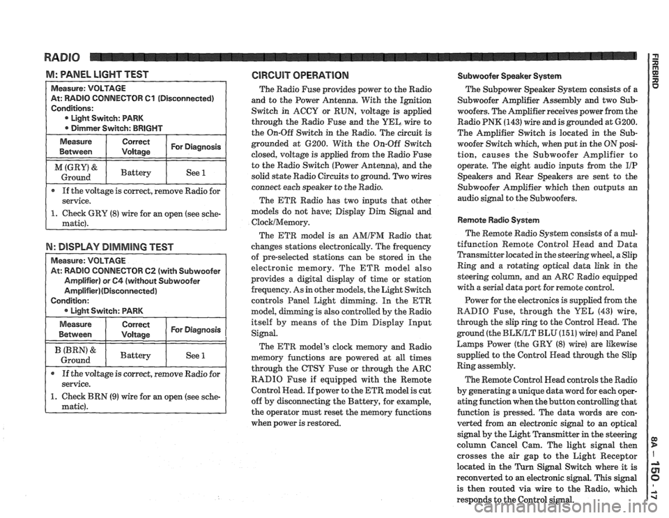
M: WNEL LIGHT TEST GlRGUlT OPERATION Subwoofer Speaker System
TOR 61 (Disconnected)
If the voltage is correct, remove Radio for
N: DISPLAY DIMMING TEST
TOW 62 (with Subwoofer
The Radio Fuse provides power to the Radio
and to the Power Antenna. With the Ignition
Switch in ACCY or RUN, voltage is applied
through the Radio Fuse and the
UEL wire to
the On-Off Switch in the Radio. The circuit is
grounded at 6200. With the On-Off Switch
closed, voltage is applied from the Radio Fuse
to the Radio Switch (Power Antenna), and the
solid state Radio Circuits to ground. Two wires
connect each speaker to the Radio.
The ETR Radio has two inputs that other
models do not have; Display Dim Signal and
ClocklMemory.
The ETR model is an AMIFM Radio that
changes stations electronically. The frequency
of pre-selected stations can be stored
in the
electronic memory. The ETR model also
provides a digital display of time or station
frequency. As in other models, the Light Switch
controls Panel Light dimming. In the
ETR
model, g is also controlled by the Radio
itself by means of the Dim Display Input
Signal.
The ETR model's clock memory and Radio
memory functions are powered at all times
through the CTSY Fuse or through the ARC
RADIO Fuse if equipped with the Remote
Control Head. If power to the ETR model is cut
off by disconnecting the Battery, for example,
the operator must reset the memory functions
when power is restored. The
Subpower Speaker
System consists of a
Subwoofer Amplifier Assembly and two Sub-
woofers. The Amplifier receives power from the
Radio PNK
(143) wire and is grounded at 6200.
The Amplifier Switch is located in the
Sub-
woofer Switch which, when put in the ON posi-
tion, causes the Subwoofer Amplifier to
operate. The eight audio inputs from the
I/P
Speakers and Rear Speakers are sent to the
Subwoofer Amplifier which then outputs an
audio signal to the Subwoofers.
Remote Radio System
The Remote Radio System consists of a mul-
tifunction Remote Control
Head and Data
Transmitter located in the steering wheel, a Slip
Ring and a rotating optical data link in the
steering
colurnn, and an ARC Radio equipped
with a serial data port for remote control.
Power for the electronics is supplied from the
RADIO Fuse, through the
YEL (43) wire,
through the slip ring to the Control Head. The
ground (the
BLKLT BLU (15 1) wire) and Pand
Larnps Power (the GRY (8) wire) are Likewise
supplied to the Control Head through the Slip
Ring assembly.
The Remote Control Head controls the Radio
by generating a unique data word for each oper-
ating function when the button controlling that
function is pressed. The data words are con-
verted from an electronic signal to an optical
signal by the Light Transmitter in the steering
column Cancel Cam. The light signal then
crosses the air gap to the Light Receptor
located in the
Turn Signal Switch where it is
reconverted to
an electronic signal. This signal
is then routed via wire to the Radio, which
responds to the Control signal.