1988 PONTIAC FIERO traction control
[x] Cancel search: traction controlPage 255 of 1825

4819 REAR AXLE
bears against the inner race of the front bearing and a
shoulder on the pinion stem. This spacer is used to
enable accurate bearing pre-load adjustment and
maintain a pre-load on both front and rear pinion
bearings, Adjustment of the fore and aft position of the
pinion is obtained by placing a shim between the rear
pinion bearing cup and axle housing. The differential
case is of two-piece construction and is supported in
the carrier by two tapered roller side bearings. Pre-load
rear axle case by inserting shims between the bearings
and the carrier. The rear axle case assembly is
positioned for proper ring gear to pinion backlash by
varying the shim thickness from side to side. The ring
gear is bolted to the case. Two side gears have splined
bores for driving the axle shafts. They are positioned
to turn in counterbored cavities in the case. The four
rear axle pinions have smooth bores and are held in
position by a pinion cross shaft, mounted and locked
in the rear axle case. All six gears are in mesh with each
other and because the pinion gears turn freely on their
shaft, they act as idler gears when the rear wheels are
turning at different speeds. The pinions and side gears
are backed by steel thrust washers.
LIMITED-SLIP REAR AXLE
The operation of the Limited-Slip differential is
the same as the standard differential, except that there
is additional friction provided by the conical clutches.
Under ordinary driving and cornering conditions, the
cones slip, allowing the outside wheel to turn faster
than the inner. Under poor traction conditions, such as
ice, snow, or loose gravel under one driving wheel, the
increased friction provided by the cones increases the
driving torque available to the wheel with the better
traction. The cones are spring loaded to provide the
increased driving torque under extremely low traction
conditions.
Operation
When the vehicle turns a corner, the outer rear
wheel must turn faster than the inner wheel. The inner
wheel, turning slower than the outer wheel, slows its
differential side gear (as the axle shaft is splined to the
side gear) and the differential pinion gears will roll
around the slowed differential side gear, driving the
other differential side gear and wheel faster.
DIAGNOSIS AND TESTING
Many noises reported as coming from the rear
axle assembly actually originate from other sources
such as tires, road surfaces, front wheel bearings, axle
bearing, engine, transmission, muffler or body
drumming. A thorough and careful check should be
made to determine the source of the noise before
disassembling the rear axle. Noise which originates in
other places cannot be corrected by adjustment or
replacement of parts in the differential. It should also
be remembered that rear axle gears, like any other
mechanical device, are not absolutely quiet and should
be accepted as being commercially quiet unless some
abnormal noise is present.
To make a systematic check for axle noise under
standard conditions, observe the following:
1. Select a level smooth asphalt road to reduce tire
noise and body drumming.
2. Check rear axle lubricant to assure correct level,
then drive car far enough to thoroughly warm up
rear axle lubricant, approximately 10 miles.
3. Note speed and RPM at which noise occurs. Stop
car and put transmission in neutral. Run engine
slowly up and down through engine speeds,
corresponding to car speed at which noise was
most pronounced, to determine if it is caused by
exhaust, muffler roar or other engine conditions.
4. Tire noise changes with different road surfaces,
but rear axle noise does not. Temporarily
inflating all tires to approximately 50 pounds
pressure
for test purposes only will materially
alter noise caused by tires, but will not affect noise
caused by rear axle. Rear axle noise usually stops
when coasting at speeds under 30 miles per hour;
however, tire noise continues, but with lower
tone, as car speed is reduced. Rear axle noise
usually changes when comparing acceleration
and coast, but tire noise remains about the same.
Distinguish between tire noise and rear axle noise
by noting if noise varies with various speeds or
sudden acceleration and deceleration; exhaust
and axle noise show variations under these
conditions while tire noise remains constant and
is more pronounced at speeds of 20 to 30 miles
per hour. Further check for tire noise by driving
car over smooth pavements or dirt roads (not
gravel) with tires at normal pressure. If noise is
caused by tires, it will noticeably change or
disappear and reappear with changes in road
surface.
5. Loose or rough front wheel bearings will cause
noise which may be confused with rear axle
noises; however, front wheel bearing noise does
not change when comparing drive and coast.
Light application of brakes while holding car
speed steady will often cause wheel bearing noise
to diminish, as this takes some weight off the
bearing. Front wheel bearings may be easily
checked for noise by jacking up the wheels and
spinning them, also by shaking wheels to
determine if bearings are loose.
6. Rear suspension rubber bushings and spring
insulators dampen out rear axle noise when
correctly installed. Check to see that no metallic
contact exists between the spring and spring seat
opening in frame or between upper and lower
control arm bushings and frame or axle housing
brackets. The track bar and torque arm must be
bolted securely. Metal-to-metal contact at those
points may result in telegraphing road noise and
normal axle noise which would not be
objectionable if dampened by bushings.
AXLE NOISES
After the noise has been determined as being in
the axle by following the above appraisal procedure,
the type of axle noise should be determined to aid in
making repairs if necessary.
Page 271 of 1825

484-18 REAR AXLE
4. With transmission in park and both wheels and
tires clear of ground, (wheels will r~tate in opp-
osite directions), measure torque required to
rotateaxle shafts with a torque
wrenchattached
to J 2619-1. If the torque reading is less than
48 N.m (35 1b.ft.) the unit should be disassembled
and repaired as required.
5. Reinstall wheel and tire assembly.
Disassemble
Limited Slip Differential.
1. Remove ring gear bolts.
NOTICE: Left hand threaded ring gear bolts.
2. Tap
ring gear off differential housing with soft
face hammer.
NOTICE: Mark differential case halves with
alignment mark before disassembly because they
could be assembled
180" off from original position.
3. Remove 8 screws holding differential housing
halves together and separate halves. 4.
Remove pinion shaft, 4 differential pinions,
thrust washers side gears, side gear shims
(if
required), spring plates, and compression springs
from housing. Discard compression springs. New
springs are required for assembly.
5. Mark each cone during disassembly to ensure
that the same brake cone will be assembled with
the same case as originally assembled. If shims
are used they must be marked so that they will be
assembled in original case half.
6. If differential bearings are damaged remove with
tool J-22888-D. (Fig. 15).
Inspect
Disassemble
The inspection procedures for the positraction
differential are the same as those for the standard
rear axle except for the side gear positioning
shims. The side gear positioning shims are used
to control case size.
1. The shims should be free of cracks, nicks, or
burrs.
2. Assemble brake cones in case and measure to
determine correct shim size. Measure the
distance from case mating surface to flat surface
on brake cone when fully seated. Select shim size
from chart below.
DISASSEMBLY INSPECTION CHART
Distance Measured mm (ins) Size
Shim Required
29.51/29.34 (1.162/1/155) no shim required.
29.64/29.54 (1.167/1.163) 0.13 (.005) shim required.
29.77D9.67 (1.172/1.168) 0.25 (.010) shim required.
Assemble
Limited Slip Differential
1.
Lubricate both sides of pinion thrust washers,
pinion bores and differential pinion shafts with
specified rear axle lube before assembling.
2. Install the 4 pinions and spherical thrust washers.
3. Replace original brake cone, shim if required, and
side gear in cap half of differential case. For shim
selection, if needed, refer to Disassembly
Inspection Chart. Apply mixture of molybdenum
disulphide and specified axle oil to face of side
gear.
NOTICE: Do not 1.eplace cone or case
independently. They must be replaced as a unit
together.
4. Install spring
plate on side gear with convex side
towards flange half.
5. Assemble differential pinion shaft, pinions, and
spherical thrust washers into cap half of
differential case with pinions meshing with side
gear. 6.
Install three new concentric thrust springs
through the center of the pinion shaft spider.
7. Assemble second spring plate and springs with
cgnvex side towards springs.
8. Coat other side gear face with molybdenum
disulphide and axle lubricant and install side gear
shim if required. Install brake cone on spring
plate.
9. Install
flange half of case on top of assembly with
oil channels aligned.
10. Install
two bolts through cases
180" apart and
tighten finger tight.
11. Axle shafts are used to align the side gear and
brake cone splines. Put a clamp on one axle shaft
so 75 mm (3 inches) extends beyond clamp.
Install differential housing onto axle shaft splines,
flanged half first.
12. Install other axle shaft through cap side of
differential case and align side gear and cone
splines.
13. Install remaining
bolts and tighten to specified
torque.
14. Install
ring gear and tighten bolts to specified
torque.
Page 414 of 1825

ENGINE COOLING 88.3
since a small oil pump driven by the separator plate
forces the silicone oil into a reservoir between the
separator plate and the front cover assembly. In this
position, the passage from this cavity to the clutch area
is closed by a slide valve. As operating conditions
produce a high radiator air temperature discharge,
above approximately 66°C
(150"F), the temperature
sensitive bi-metal coil tightens to move the slide valve
(attached to the coil) which opens a port in the
separator plate. This allows a flow of silicone oil into
the clutch chamber to engage the clutch, providing a
maximum fan speed of approximately 2200 rpm. The
clutch coil is calibrated so that, with a road load at an
ambient temperature of approximately 32°C
(90T), the
clutch is just at a point of shift between high and low
fan speed. No attempt should be made to disturb the
calibration of the engine clutch fan assembly as each
assembly is individually calibrated at the time of
manufacture. Under certain temperature conditions
there is a lateral movement at the fan tip which should
not be considered as a hub or bearing failure. This
condition is a design feature of the clutch assembly
which allows up to approximately
1/4" lateral
movement measured at the fan tip.
Testing a clutch fan by holding the small hub
with one hand and rotating the aluminum housing in
a
clockwise/counter-clockwise motion will cause the
clutch to freewheel, which is a normal condition when
operated in this manner. This should not be considered
a test by which replacement is determined.
Temperature Switch
This switch activates a warning lamp in the
instrument cluster if the engine overheats. With
optional instrumentation, a temperature gage replaces
the warning lamp and the temperature switch is
replaced with a transducer. See Section
8A for
Temperature Switch location and diagnosis.
Coolant Temperature Fan Switch
This switch regulates voltage to the coolant fan
relay, which operates the fan whenever the engine
coolant temperature exceeds 230"
F (110" C). For
location and diagnosis see Section 8A for Coolant
Temperature Fan Switch.
Thermostat
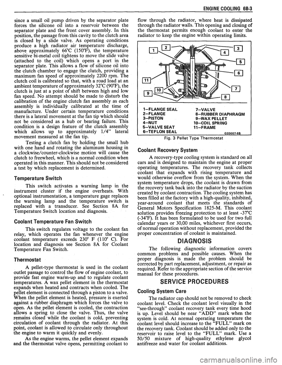
A pellet-type thermostat is used in the coolant
outlet passage to control the flow of engine coolant, to
provide fast engine warm-up and to regulate coolant
temperatures.
A wax pellet element in the thermostat
expands when heated and contracts when cooled. The
pellet element is connected through a piston to a valve.
When the pellet element is heated, pressure is exerted
against a rubber diaphragm which forces the valve to
open. As the pellet element is cooled, the contraction
allows a spring to close the valve. Thus, the valve
remains closed while the coolant is cold, preventing
circulation of coolant through the radiator. At this
point, coolant is allowed to circulate only throughout
the engine to warm it quickly and evenly.
As the engine warms, the pellet element expands
and the thermostat valve opens, permitting coolant to flow
through the radiator, where heat is dissipated
through the radiator walls. This opening and closing of
the thermostat permits enough coolant to enter the
radiator to keep the engine within operating limits.
Fig. 3 Pellet Type Thermostat
Coolant Recovery System
A recovery-type cooling system is standard on all
cars and is designed to maintain the engine at proper
operating temperatures. The recovery tank collects
coolant that expands with rising temperature and
would otherwise overflow from the system. When the
system temperature drops, the coolant is drawn from
the recovery tank back into the radiator by the suction
created by coolant contraction. The cooling system has
been filled at the factory with a high-quality, inhibited,
year-around coolant that meets the standards of
General Motors Specification 1825-M. This coolant
solution provides freezing protection to at least -37°C
(-34°F). It has been formulated to be used for two full
calendar years or
30,OO miles, whichever first occurs,
of normal operation without replacement, provided the
proper concentration of coolant is maintained.
DIAGNOSIS
The following diagnostic information covers
common problems and possible causes. When the
proper diagnosis is made the problem should be
corrected by part replacement, adjustment, or repair as
required. Refer to the appropriate section of the service
manual for these procedures.
SERVICE PROCEDURES
Cooling System Care
The radiator cap should not be removed to check
coolant level. Check the coolant level visually in the
"see-through" coolant recovery tank every time hood
is up. Level should be near "ADD" mark when the
system is cold. At normal operating temperature the
coolant level should increase to the "FULL" mark on
the recovery tank. Coolant should be added only to the
reservoir to raise level to the "FULL" mark. Use a
50/50 mixture of high-quality ethylene glycol
antifreeze and water for coolant additions.
Page 1784 of 1825

SEATS - F STYLE 9H-1
SEC"IC"0N 9H
SEATS
NOTICE: Lap belt to floor pan and shoulder belt to roof panel or quarter panel fasteners are important
attaching parts in that they could affect the performance of vital parts and systems, and/or could result in major
repair expense. They must be replaced with one of the same part number or with an equivalent part if replacement
becomes necessary. Do not use a replacement part of lesser quality or substitute design. Torque values must be
used as specified during reassembly to assure proper retention of these parts.
CONTENTS
Restraint Systems ........................................... 9H- 1
Lap and Shoulder Belts
............................... 9H-1
Comfort Lock Operational Checks
and Requirements
.................................... 9H- 1
Front Seat Shoulder Belt Retractor
............ 9H-2
Child Seat
...................................................... 9H-2
............................... .................. -.rant Seats .. 9H-5
Mead Restraint
............................................. 9H-5
Reclining
Seatback ................................... 9H-6
Front
Seatback ........................................... 9H-7
Inertia Lock Check
...................................... 9H-7
............................... Manual Recliner Check 9H-7
........................... Seat Torque Specifications 9H-8
Manual Seat
- Diagnosis Chart ................... 9H-8
..................... Power Seat - Diagnosis Chart 9H-9
RESTRAINT SYSTEMS
LAP
AND SHOULDER BELTS
The front seat belts incorporate a 4-to-8 second
fasten seat belt reminder lamp and sound signal
designed to remind the driver if the lap and shoulder
belts are not fastened when the ignition is turned to the
on position. If the driver's seat belt
is buckled, the
alarm will not operate; however, the fasten seat belt
xminder lamp will stay on for a 4-to-8 second period.
,, the driver's seat belt is not buckled, the reminder
lamp and sound signal will automatically shut off after
the 4-to-8 second interval. To diagnose a system
failure, refer to Seat Belt Reminder
Lamp/Alarm
Diagnosis in Section 8A.
The shoulder belt is attached to the front seat lap
belt latch plate and connected to an inertia locking
retractor installed to the roof panel above the right and
left side of the front seat. The shoulder belt remains
unlocked to allow the occupants to move freely while
the vehicle is being operated. When the vehicle
decelerates or changes direction abruptly, the shoulder
belt is locked in position by a pendulum that causes a
locking bar to engage a cog of the retractor mechanism.
The retractor has a comfort lock feature that
allows the occupant to adjust the shoulder belt for
proper fit and comfort. When engaged, the comfort
lock prevents full retraction of the webbing to eliminate
occupant discomfort due to webbing load on the
shoulder. The occupant can readjust the comfort lock
during vehicle operation as described below.
When servicing or replacing lap and shoulder
belts, refer to the following precautionary items: Front
Seat Adjustments
............................... 9H- 10
Manual Seat Control Arm Knob
................ 9H-10
Front Seat Assembly
.................................... 9H- 1 1
Seat Adjuster Assembly ............................. 9H-11
Six-way Seat Adjuster .................................. 9H- 12
Power Seat Switch
........................................ 9H-15
Four-way Manual Seat Adjuster
................. 9H-15
Seatback Lock Striker/Side Bar Stop .......... 9H-15
High Performance AQ9 Seat
(2FS87) ......... 9H-15
................. .................................... Rear Seats ... 9H- 19
........................................ Cushion Assembly 9H- 19
................................ Folding Rear Seatback 9H- 19
........................... Seatback Lock Assembly 9H-20
.................................. Seatback Lock Striker 9H-20
1. Lap and shoulder belts will be serviced as follows:
a. Retractor
portion(s) of
front seat lap and
shoulder belt for outboard passenger and
driver.
b. Buckle portion of front seat lap belt for
outboard passenger and driver.
c. All belts other than those mentioned in
above steps a and b will be serviced in
complete sets.
d. Do not intermix standard and deluxe belts
on front or rear seats.
2. Keep sharp edges and damaging objects away
from belts.
3. Avoid bending or damaging any portion of the
belt buckle or latch plate.
4. Do not bleach or dye belt webbing (clean with a
mild soap solution and water).
5. When installing lap or shoulder belt anchor bolt,
start bolt by hand to assure that bolt is threaded
straight.
NOTICE: See NOTICE on page 9H-1 of this
section.
6. Do not attempt repairs on lap or shoulder belt
retractor mechanisms or lap belt retractor covers.
Replace with new service replacement parts.
Comfort Lock Operational Checks and Requirements
The shoulder belt comfort lock feature must
function as follows:
1. Extend the webbing from the retractor to a
distance approximating buckled position.