1988 PONTIAC FIERO tps adjustment
[x] Cancel search: tps adjustmentPage 559 of 1825
6EZ-C1-4 S.OL (VIN E) DRIVEABILITY AND EMISSIONS
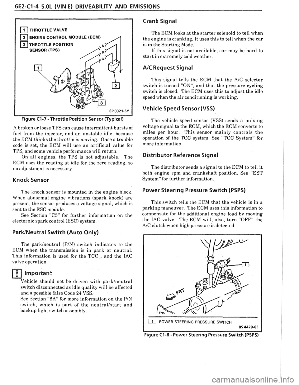
THROTTLE VALVE
ENGINE CONTROL MODULE (ECM)
THROTTLE POSITION
(TPS)
8P 0321.
Figure C1-7 - Throttle Position Sensor (Typical)
A brolten or loose TPS can cause intermittent bursts of
fuel from the injector, and an unstable idle, because
the ECM thinks the throttle is moving. Once a trouble
code is set, the ECM will use an artificial value for
TPS, and some vehicle performance will return.
On all engines, the TPS is not adjustable. The
ECM uses the reading at idle for the zero reading, so
no adjustment is necessary.
Knock Sensor
The knock sensor is mounted in the engine block.
When abnormal engine vibrations (spark knock) are
present, the sensor produces a voltage signal, which is
sent to the ESC module.
See Section
"C5" for further information on the
electornic spark control
(ESC) system.
ParklNeutral Switch (Auto Only)
The parWneutra1 (PIN) switch indicates to the
ECM when the transmission is in park or neutral.
This information is used for the TCC
, and the IAC
valve operation.
Important
Vehicle should not be driven with parklneutral
switch disconnected as idle quality will be affected
and a possible false Code
24 VSS.
See Section
"8A" for more information on the PIN
switch, which is part of the neutrallstart and
backup light switch assembly.
Crank Signal
The ECM looks at the starter solenoid to tell when
the engine is cranking. It uses this to tell when the car
is in the Starting Mode.
If this signal is not available, car may be hard to
start in extremely cold weather.
AIC Request Signal
This signal tells the ECM that the AJC selector
switch is turned
"ON", and that the pressure cycling
switch is closed. The ECM uses this to adjust the idle
speed when the air conditioning is working.
Vehicle Speed Sensor (VSS)
The vehicle speed sensor (VSS) sends a pulsing
voltage signal to the ECM, which the ECM converts to
miles per hour. This sensor mainly controls the
operation of the TCC system. See "TCC System" for
more information.
Distributor Reference Signal
The distributor sends a signal to the ECM to tell it
both engine rpm and crankshaft position. See "EST
System" for further information.
Power Steering Pressure Switch (PSPS)
I
This switch tells the ECM that the vehicle is in a
parking maneuver.
The ECM uses this information to
compensate for the additional engine load by moving
the IAC valve. The ECM will, also, turn
"OFF" the
A/C clutch when high pressure is detected.
( POWER STEERING PRESSURE SWITCH
Figure C'I-8 - Power Steering Pressure Switch (PSPS)
Page 565 of 1825
6EZ-Cl-10 5.OL (VIN El DRIVEABILITY AND EMISSIONS
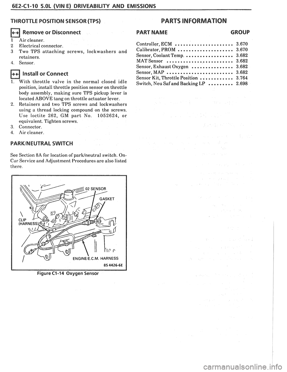
THROTTLE POSIT ION SENSOR (TPS)
n Remove or Disconnect
1 Air cleaner.
2 Electrical connector.
3 Two TPS attaching screws, lockwashers and
retainers.
4. Sensor.
Install or Connect
1. With throttle valve in the normal closed idle
position, install throttle position sensor on throttle
body assembly, making sure TPS pickup lever is
located ABOVE tang on throttle actuator lever.
2. Retainers and two TPS screws and lockwashers
using a thread locking compound on the screws.
Use loctite 262,
GM part No. 1052624, or
equivalent. Tighten screws.
3. Connector.
4. Air cleaner.
PARKINEUTRAL SWITCH
See Section 8A for location of paruneutral switch. On-
Car Service and Adjustment Procedures are also listed
there.
PARTS INFORMATION
PART NAME GROUP
Controller, ECM ..................... 3.670
Calibrator, PROM .................... 3.670
Sensor, Coolant Temp. ................. 3.682
MAT Sensor ........................ 3.682
Sensor, Exhaust Oxygen ............... 3.682
Sensor, MAP ........................ 3.682
Sensor Kit, Throttle Position ............ 3.764
Switch, Neu Saf and Backing LP ......... 2.698
Figure C1-14 Oxygen Sensor
Page 586 of 1825
DRIVEABILITY AND EMISSIONS - 5.0L (VIN E) 6EZ-CZ-11
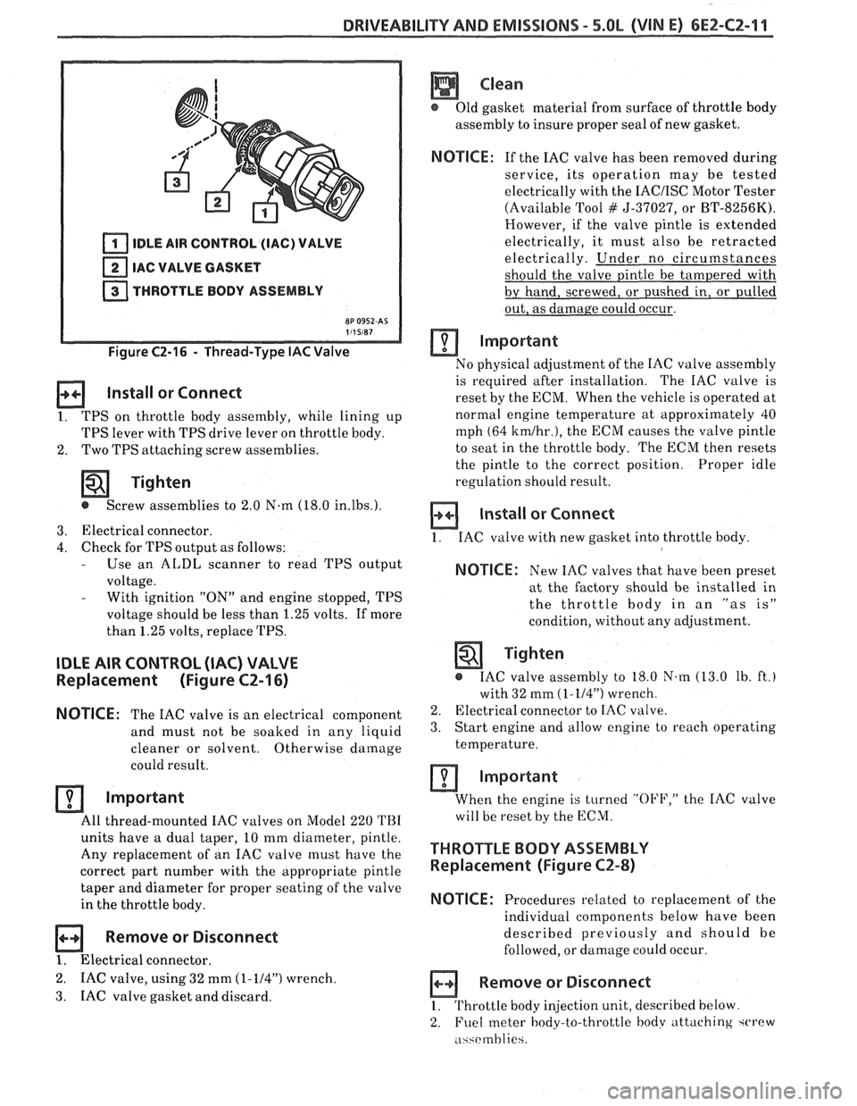
IDLE AIR CONTROL (IAC) VALVE
IAC VALVE GASKET
THROTTLE BODY ASSEMBLY
Figure C2-16 - Thread-Type IAC Valve
Install or Connect
1. TPS on throttle body assembly, while lining up
TPS lever with TPS drive lever on throttle body.
2. Two
TPS attaching screw assemblies.
Tighten
@ Screw assemblies to 2.0 N-m (18.0 in.lbs.).
3. Electrical connector.
4. Check for TPS output as follows: - Use an ALDL scanner to read TPS output
voltage.
- With ignition "ON" and engine stopped, TPS
voltage should be less than 1.25 volts. If more
than 1.25 volts, replace TPS.
IDLE AIR CONTROL (IAC) VALVE
Replacement (Figure CZ-16)
NOTICE:
The IAC valve is an electrical
component
and must not be soaked in any liquid
cleaner or solvent. Otherwise
damage
could result.
Important
All thread-mounted IAC valves on Model 220 TBI
units have a dual taper, 10 mm diameter, pintle.
Any replacement of an IAC valve must have the
correct part number with the appropriate pintle
taper and diameter for proper seating of the valve
in the throttle body.
Remove or Disconnect
1. Electrical connector.
2. IAC valve, using 32 mm (1-114") wrench.
3. IAC
valve gasket and discard.
Clean
@ Old gasket material from surface of throttle body
assembly to insure proper seal of new gasket.
NOTICE: If the IAC valve has been removed during
service, its operation may be tested
electrically with the
IACIISC Motor Tester
(Available Tool
# 5-37027, or BT-8256K).
However, if the valve pintle is extended
electrically, it must also be retracted
electrically. Under no circumstances
should the valve pintle be tampered with
by hand, screwed, or pushed in, or pulled
out, as damage could occur.
Important
No physical adjustment of the IAC valve assembly
is required after installation. The IAC valve is
reset by the ECM. When the vehicle is operated at
normal engine temperature at approximately 40
mph (64
kmlhr.), the ECM causes the valve pintle
to seat in the throttle body. The ECM then resets
the pintle to the correct position. Proper idle
regulation should result.
Install or Connect
1. IAC valve with new gasket into throttle body
NOTICE: New IAC valves that have been preset
at the factory should be installed in
the throttle
body in an "as is"
condition, without any adjustment.
Tighten
@ IAC valve assembly to 18.0 N.m (13.0 lb. ft.)
with 32 mm
(1-114") wrench.
2. Electrical connector to IAC valve.
3. Start engine and allow engine to reach operating
temperature.
Important
When the engine is turned "OFF," the IAC valve
will be reset by the ECM.
THROTTLE BODY ASSEMBLY
Replacement (Figure CZ-8)
NOTICE:
Procedures related to replacement of the
individual components below have been
described previously and should be
followed, or damage could occur.
Remove or Disconnect
1. Throttle body injection unit, described below
2. Fuel
meter body-to-throttle hodv attaching ~CI'PW
.i~~rmhlie
Page 587 of 1825
6E2-C2-12 DRIVEABILITY AND EMISSIONS - 5.0b (VIN E)
3. Fuel meter body assembly.
4. Throttle body-to-fuel meter body gasket. Discard
gasket.
a Disassemble
@ TPS from old throttle body, according to previous
instructions, for reuse on new throttle body. (New
IAC valve comes with new throttle body.)
Assemble
@ TPS onto replacement throttle body assembly,
according to previous instructions.
Install or Connect
1. New throttle body-to-fuel meter body gasket.
2. Fuel meter body assembly on throttle body
assembly.
3. Fuel meter body-throttle
body attaching screw
assemblies that have been coated with locking
compound.
Tighten
@ Attaching screw assemblies to 4.0 N.m
(35.0 Ib. in.).
4. TBI
unit onto engine, as described below.
MllMiMhlM IDLE SPEED CHECK
The idle stop screw, used in mechanically setting
minimum engine idle speed has been set at the factory
and should not require further adjustment. However,
to check that the setting is correct, proceed as follows:
I. Plug any vacuum ports, as required.
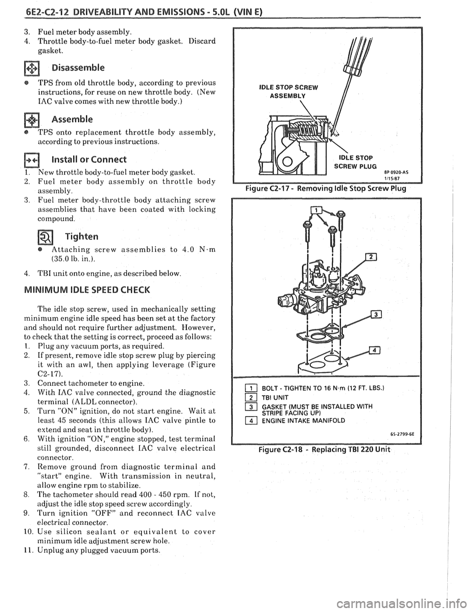
2. If present, remove idle stop screw plug by piercing
it with an awl, then applying leverage (Figure
C2-17).
3. Connect tachometer to engine.
4. With IAC valve connected, ground the diagnostic
terminal
(ALDL connector).
5.
Turn "ON" ignition, do not start engine. Wait at
least 45 seconds (this allows IAC valve pintle to
extend and seat in throttle body).
6. With ignition "ON," engine stopped, test terminal
still grounded, disconnect
IAC valve electrical
connector.
7, Remove ground from diagnostic terminal and
"startJ' engine. With transmission in neutral,
allow engine rpm to stabilize.
8. The tachometer should read 400 - 450 rpm. If not,
adjust the idle stop speed screw accordingly.
9. Turn ignition "OFF" and reconnect IAC valve
electrical connector.
10. Use silicon sealant or equivalent to cover
minimum idle adjustment screw hole.
11. Unplug any plugged vacuum ports.
1 BOLT - TIGHTEN TO 16 N,rn (12 FT. LBS.)
TBI UNIT
1 GASKET (MUST BE INSTALLED WITH STRIPE FACING UP) ENGINE INTAKE MANIFOLD
Figure C2-18 - Replacing TBI 220 Unit
Page 644 of 1825
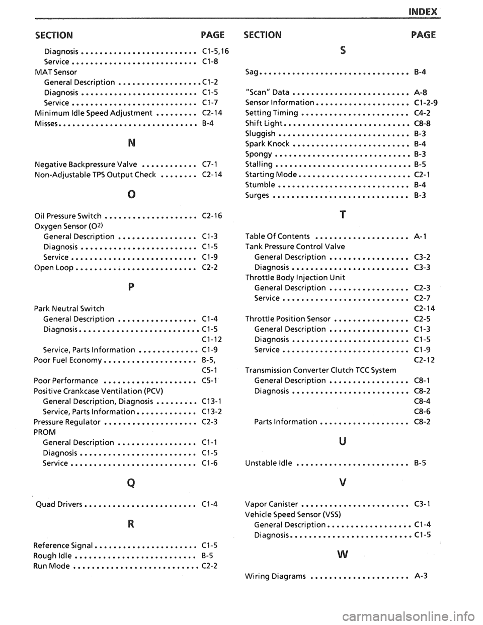
INDEX
SECT ION PAGE
Diagnosis ......................... C1.5. 16
Service
........................... C1-8
MAT Sensor
General Description
.................. C1-2
Diagnosis
......................... C1-5
Service
........................... C1-7
Minimum
Idle Speed Adjustment ......... C2-14
Misses
.............................. B-4
Negative Backpressure Valve
............ C7-1
Non-Adjustable TPS Output Check
........ C2-14
Oil Pressure Switch
.................... C2-16
Oxygen Sensor
(02)
General Description ................. C1-3
Diagnosis ......................... C1-5
Service
........................... C1-9
Open Loop
.......................... C2-2
Park Neutral Switch
General Description
................. C1-4
Diagnosis
.......................... C1-5
C1-12
Service. Parts Information
............. C1-9
Poor Fuel Economy
.................... B.5.
C5- 1
Poor Performance
.................... C5-1
Positive Crankcase Ventilation (PCV)
General Description. Diagnosis
......... C13-1
Service. Parts Information
............. C13-2
Pressure Regulator
.................... C2-3
PROM General Description
................. C1-1
Diagnosis ......................... C1-5
Service
........................... C1-6
....................... Quad Drivers. C1-4
Reference Signal
...................... C1-5
Rough
Idle .......................... B-5
RunMode ........................... C2-2
SECTION PAGE
S
Sag ................................ B-4
"Scan" Data
......................... A-8
Sensor Information
.................... C1-2-9
Setting Timing
....................... C4-2
Shift Light
........................... C8-8
Sluggish
............................ B-3
Spark Knock
......................... B-4
Spongy
............................. 8-3
Stalling ............................. B-5
Starting Mode
........................ C2-1
Stumble
............................ B-4
Surges
............................. B-3
Table Of Contents
.................... A-1
Tank Pressure Control Valve
General Description
................. C3-2
Diagnosis
......................... C3-3
Throttle Body Injection Unit
General Description
................. C2-3
Service
........................... C2-7
C2- 14
Throttle Position Sensor
................ C2-5
General Description
................. C1-3
Diagnosis
......................... C1-5
Service
........................... C1-9
C2- 12
Transmission Converter Clutch TCC System
General Description
................. C8-1
Diagnosis
......................... C8-2
C8-4 C8-6
Parts Information
................... C8-2
Unstable
Idle ........................ B-5
....................... Vapor Canister C3-1
Vehicle Speed Sensor (VSS)
.................. General Description C1-4
Diagnosis
......................... 4.5
..................... Wiring Diagrams 8-3
Page 683 of 1825
6E3-A-38 2.8b (VIM S) DRIVEABILITY AND EMISSIONS
FRONT VIEW OF CONNECTOR
MODE SIGNAL
5V REFERENCE
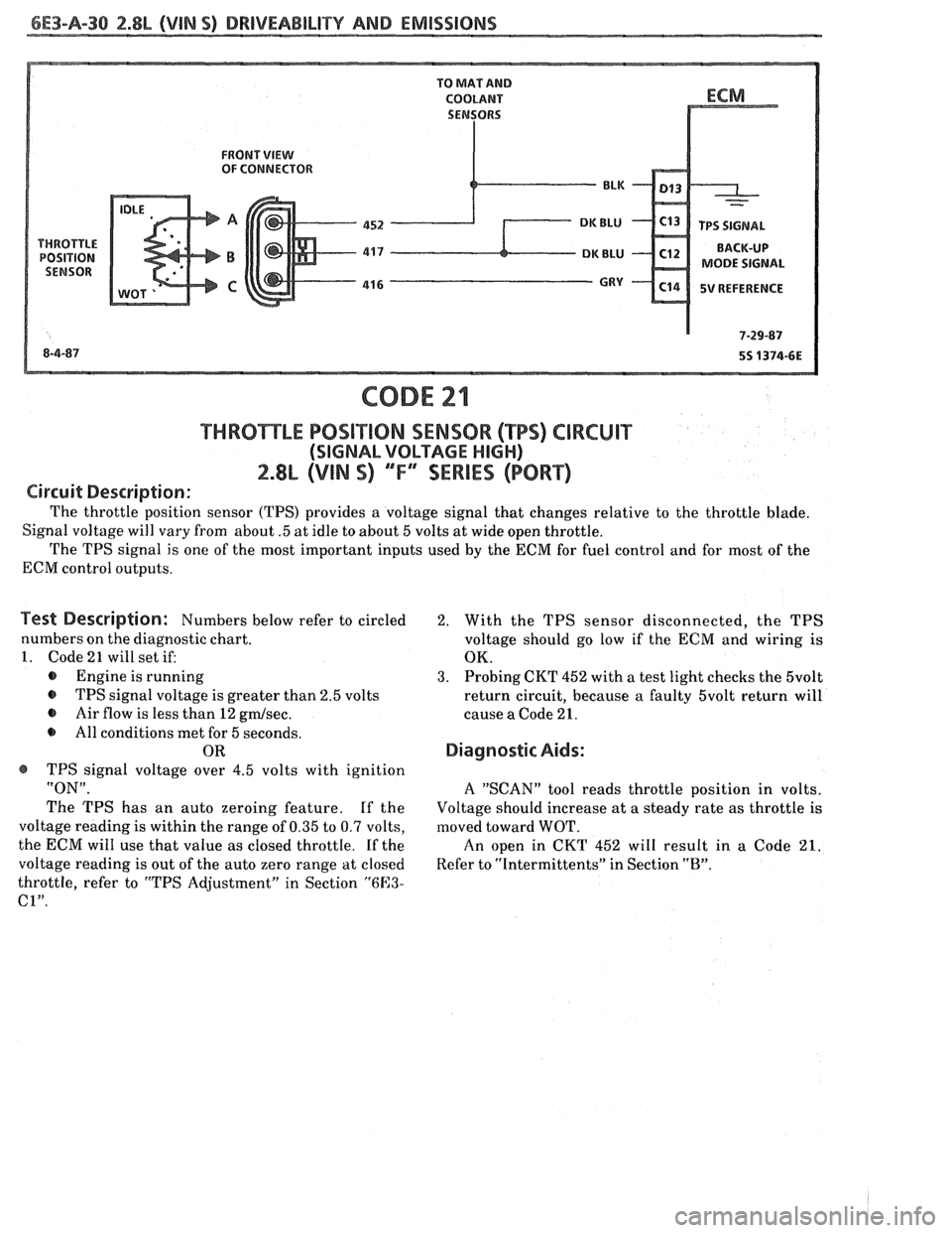
THRBmLE POSiT10N SENSOR (TPS) CIRCUIT
(SIGNAL VOLTAGE HIGH)
2.8L (VIN S) ""F-SERIES (PORT)
Circuit Description:
The throttle position sensor (TPS) provides a voltage signal that changes relative to the throttle blade.
Signal voltage will vary from about
.5 at idle to about 5 volts at wide open throttle.
The TPS signal is one of the most important inputs used by the ECM for fuel control and for most of the
ECM control outputs.
Test Description: Numbers below refer to circled
numbers on the diagnostic chart.
1. Code 21 will set if:
@ Engine is running
@ TPS signal voltage is greater than 2.5 volts
@ Air flow is less than 12 gmlsec.
All conditions met for 5 seconds.
OR
@ TPS signal voltage over 4.5 volts with ignition
"ON".
The TPS has an auto zeroing feature. If the
voltage reading is within the range of 0.35 to 0.7 volts,
the ECM will use that value as closed throttle.
If the
voltage reading is out of the auto zero range at closed
throttle, refer to "TPS Adjustment" in Section
"6E3-
C1".
2. With the TPS sensor disconnected, the TPS
voltage should go low if the
ECM and wiring is
OK.
3. Probing CKT 452 with a test light checks the 5volt
return circuit, because a faulty 5volt return will
cause a Code 21.
Diagnostic Aids:
A "SCAN" tool reads throttle position in volts.
Voltage should increase at a steady rate as throttle
is
moved toward WOT.
An open in CKT 452 will result in a Code 21.
Refer to "Intermittents" in Section "B".
Page 685 of 1825
6E3-A-32 2.8L (VIN S) DRIVEABILITY AND EMISSIONS
FRONT VIEW OF CONNECTOR
MODE SIGNAL
5V REFERENCE
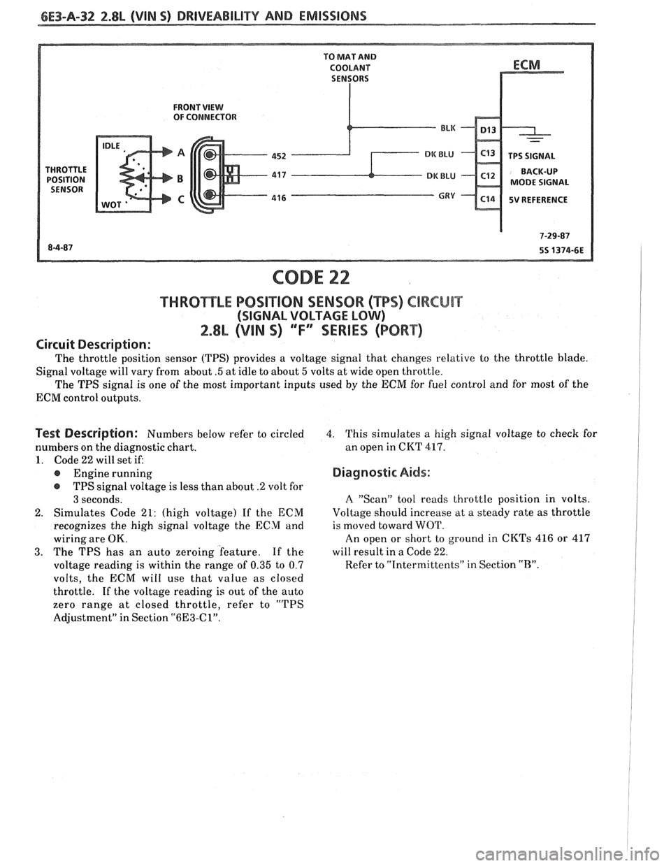
CODE 22
f HRO"I$E"LE POSlTlON SENSOR ("BPS) ClRCUlT
(SIGNAL VOLTAGE LOW)
2.8L (VIN 9) "F" "SERIES (PORT)
Circuit Description:
The throttle position sensor (TPS) provides a voltage signal that changes relative to the throttle blade.
Signal voltage will vary from about
.5 at idle to about 5 volts at wide open throttle.
The TPS signal is one of the most important inputs used
by the ECM for fuel control and for most of the
ECM control outputs.
Test Description: Numbers below refer to circled
numbers on the diagnostic chart.
1. Code 22 will set if:
@ Engine running
@ TPS signal voltage is less than about .2 volt for
3 seconds.
2. Simulates Code 21: (high voltage) If the ECM
recognizes the high signal voltage the ECM and
wiring are OK.
3. The TPS has an auto zeroing feature. If the
voltage reading is within the range of
0.35 to 0.7
volts, the ECM will use that value as closed
throttle.
If the voltage reading is out of the auto
zero range at closed throttle, refer to "TPS
Adjustment" in Section
"6E3-Cl".
4. This simulates a high signal voltage to check for
an open in CKT
417.
Diagnostic Aids:
A "Scan" tool reads throttle position in volts.
Voltage should increase at a steady rate as throttle
is moved toward WOT.
An open or short to ground in CKTs 416 or 417
will result in a Code
22.
Refer to "Intermittents" in Section "B".
Page 715 of 1825
6E3-B-6 2.8L (VIN 5) DRIVEABILITY AND EMISSIONS
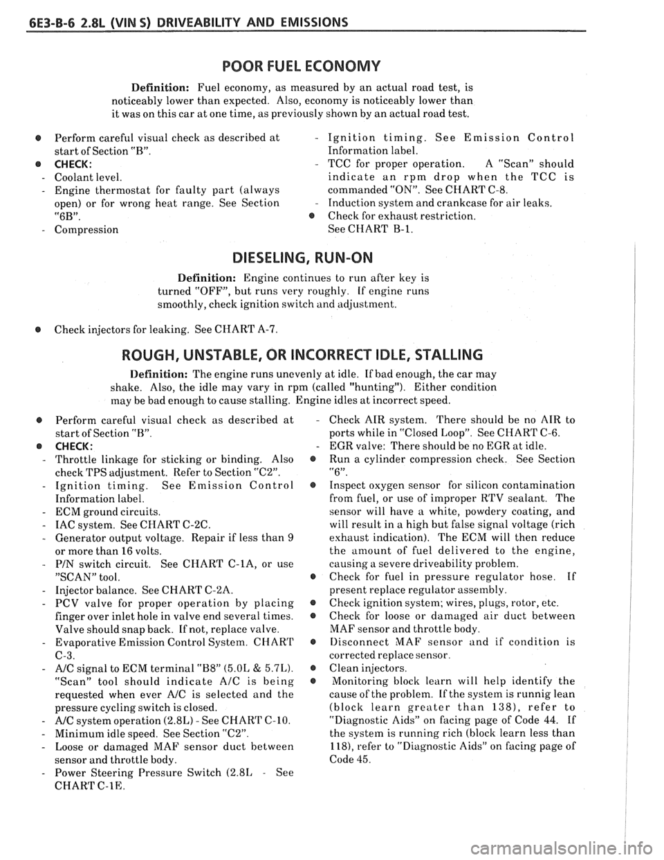
POOR FUEL ECONOMY
Definition: Fuel economy, as measured by an actual road test, is
noticeably lower than expected. Also, economy is noticeably lower than
it was on this car at one time, as previously shown by an actual road test.
@ Perform careful visual check as described at
start of Section "B".
8 CHECK:
- Coolant level.
- Engine thermostat for faulty part (always
open) or for wrong heat range. See Section
"6B".
- Compression
- Ignition timing. See Emission Control
Information label.
- TCC for proper operation. A "ScanJ' should
indicate an rpm drop when the TCC is
commanded "ON". See CHART C-8.
- Induction system and crankcase for air leaks.
8 Check for exhaust restriction.
See CHART
B-1.
DIESELING, RUN-ON
Definition: Engine continues to run after key is
turned "OFF", but runs very roughly. If engine runs
smoothly, check ignition switch and adjustment.
8 Check injectors for leaking. See CHART A-7.
ROUGH, UNSTABLE, OR INCORRECT IDLE, STALLING
Definition: The engine runs unevenly at idle. If bad enough, the car may
shake. Also, the idle may vary in rpm (called "hunting"). Either
condition
may be bad enough to cause stalling. Engine idles at incorrect speed.
@ Perform careful visual check as described at
start of Section "B".
@ CHECK:
- Throttle linkage for sticking or binding. Also
check TPS adjustment. Refer to Section
"C2".
- Ignition timing. See Emission Control
Information label.
- ECM ground circuits.
- IAC system. See CHART C-2C.
- Generator output voltage. Repair if less than 9
or more than 16 volts.
- PIN switch circuit. See CHART C-lA, or use
"SCAN" tool.
- Injector balance. See CHART C-'LA.
- PCV valve for proper operation by placing
finger over inlet hole in valve end several times.
Valve should snap back. If not, replace valve.
- Evaporative Emission Control System. CHART
C-3.
- A/C signal to ECM terminal "B8" (5.OL & 5.7L).
"Scan" tool should indicate AIC is being
requested when ever
A/C is selected and the
pressure cycling switch is closed.
- A/C system operation (2.8L) - See CHAR'l' (2-10.
- Minimum idle speed. See Section "C2".
- Loose or damaged MAF sensor duct between
sensor and throttle body.
- Power Steering Pressure Switch (2.81, - See
CHART
C-1E.
Check AIR system. There should be no AIR to
ports while in "Closed Loop". See CHART C-6.
EGR valve: There should be no EGR at idle.
Run a cylinder compression check. See Section
"6". Inspect oxygen sensor for silicon contamination
from fuel, or use of improper RTV sealant. The
sensor will have a white, powdery coating, and
will result in a high but false signal voltage (rich
exhaust indication). The ECM will then reduce
the
amount of fuel delivered to the engine,
causing a severe driveability problem.
Check for fuel in pressure regulator hose. If
present replace regulator assembly.
Check ignition system; wires, plugs, rotor, etc.
Check for loose or damaged air duct between
MAF sensor and throttle body.
Ilisconnect MAF sensor and if condition is
corrected replace sensor.
Clean injectors.
Monitoring block learn will help identify the
cause of the problem. If the system is runnig lean
(block learn greater than
138), refer to
"Diagnostic Aids" on facing page of Code
44. If
the system is running rich (block learn less than
118), refer to "Diagnostic Aids'' on facing page of
Code 45.