1988 PONTIAC FIERO wiring diagram
[x] Cancel search: wiring diagramPage 525 of 1825
6EZ-A-34 5.OL (WIN E) DRIVEABILITY AND EMISSIONS
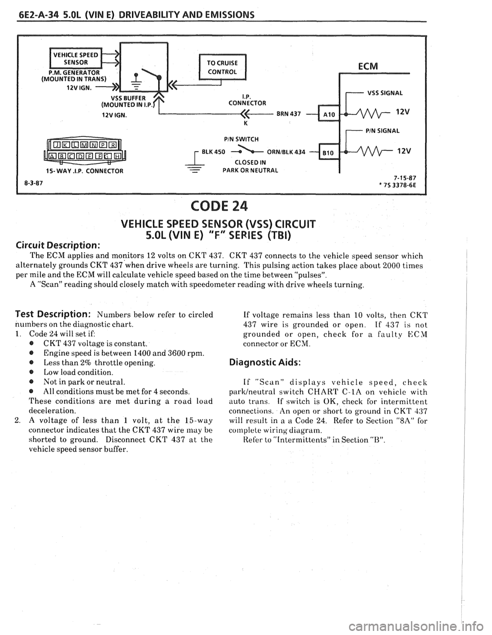
ECM
I.P.
8RN 437
K 7 PIN SIGNAL
PIN SWITCH
r ELK450 12v
1 CLOSED IN - 15- WAY .I.P. CONNECTOR - - PARK OR NEUTRAL I
CODE 24
VEHICLE SPEED SENSOR (VSS) CIRCUIT
5.OL (VIN E) "F" SERIES (TBI)
Circuit Description:
The ECM applies and monitors 12 volts on CKT 437. CKT 437 connects to the vehicle speed sensor which
alternately grounds CKT
437'when drive wheels are turning. This pulsing action takes place about 2000 times I
per mile and the ECM will calculate vehicle speed based on the time between "pulsesJ'.
A "Scan" reading should closely match with speedometer reading with drive wheels turning.
I
Test Description: Numbers below refer to circled
numbers on the diagnostic chart.
1. Code 24 will set if:
@ CKT 437 voltage is constant.
@ Engine speed is between 1400 and 3600 rpm.
@ Less than 2% throttle opening.
@ Low load condition.
@ Not in park or neutral.
@ All conditions must be met for 4 seconds.
These conditions are met during a road load
deceleration.
2.
A voltage of less than 1 volt, at the 15-way
connector indicates that the CKT 437 wire
may be
shorted to ground.
Disconnect CKT 437 at the
vehicle speed sensor buffer. If
voltage remains less than 10 volts, then CKT
437 wire is grounded or open.
If 437 is not
grounded or open, check for a faulty
KCYI
connector or ECM.
Diagnostic Aids:
If "Scan" displays vehicle speed, check
parWneutra1 switch CHART C-LA on vehicle with
auto trans.
If switch is OK, check for intermittent
connections.
An open or short to ground in CKT 437
will result in
a a Code 24. Refer to Section "$A" for
col~lplete wiring diagram.
Refer to
"[ntermittents" in Section "B".
Page 548 of 1825
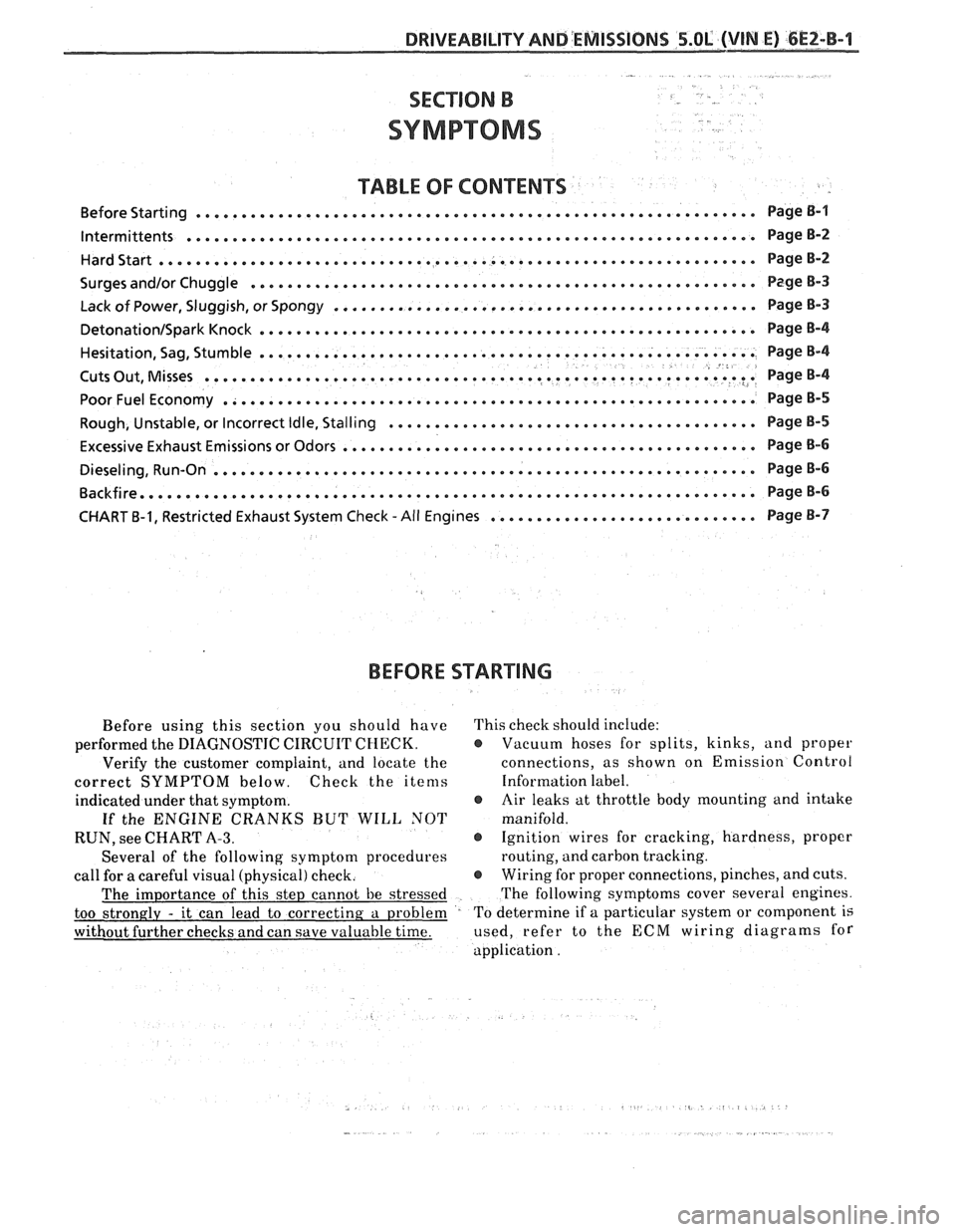
TABLE OF CONTENTS
............................................................. Before Starting Page B-1
lntermittents .............................................................. PageB-2
HardStart........,........................................................ PageB-2
...................... .................. Surges and/or Chuggle .... ........ ... Page B-3
.............................................. Lack of Power, Sluggish, or Spongy Page 8-3
DetonationISparkKnock ...................................................... PageB-4
...................................................... Hesitation,
Sag, Stumble Page B-4 8 .......................................................... Cuts Out, Misses ? .I Page 8-4
PoorFuelEconomy .......................................................... PageB-5
........................................ Rough, Unstable, or Incorrect Idle, Stalling Page
B-5
............................................. Excessive Exhaust Emissions or Odors Page
B-6
........................................................... Dieseling, Run-on Page B-6
Backfire......,..,.........,............................................... PageB-6
............................. CHART B-1, Restricted Exhaust System Check -All Engines Page B-7
BEFORE
STARTING
Before using this section you should have This check should include:
performed the DIAGNOSTIC CIRCUIT
CHECK. @ Vacuum hoses for splits, kinks, and proper
Verify the customer complaint, and locate the connections,
as shown on Emission Control
correct SYMPTOM below. Check the items Information label.
indicated under that symptom.
@ Air leaks at throttle body mounting and intake
If the ENGINE CRANKS BUT WILL NOT manifold.
RUN, see CHART
A-3. @ Ignition wires for cracking, hardness, proper
Several of the following symptom procedures routing,
and carbon tracking.
call for a careful visual (physical) check.
@ Wiring for proper connections, pinches, and cuts.
The importance of this step cannot be stressed The
following symptoms cover several engines.
too strongly
- it can lead to correcting a problem To
determine if a particular system or component is
without further checks and can save valuable time. used,
refer to the ECCM wiring diagrams for
application .
Page 555 of 1825
6EZ-C-1 5.OL (VIN E) DRIVEABILITY AND EMISSIONS
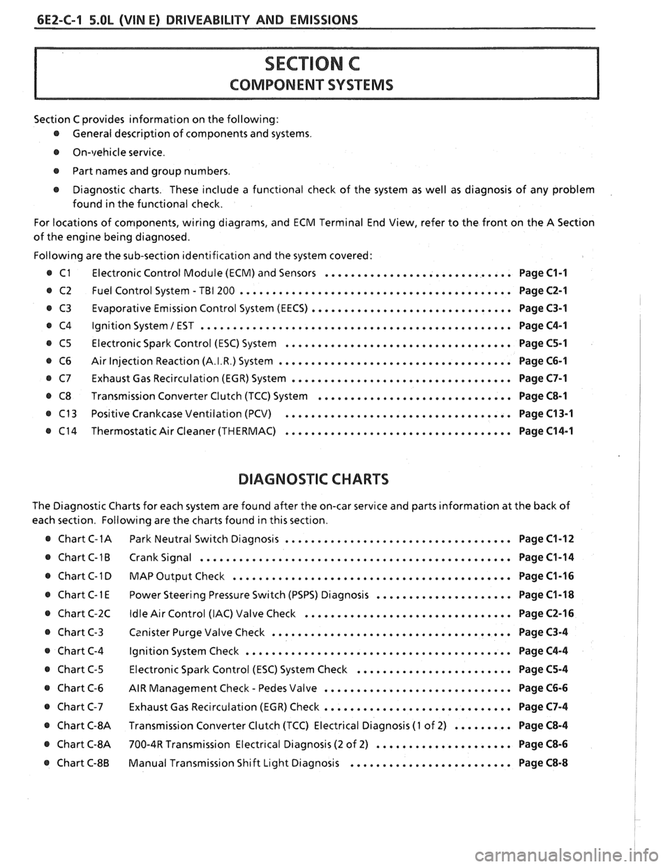
Section C provides information on the following:
@ General description of components and systems.
@ On-vehicle service.
@ Part names and group numbers.
@ Diagnostic charts. These include a functional check of the system as well as diagnosis of any problem
found in the functional check.
For locations of components, wiring diagrams, and ECM Terminal End View, refer to the front on the A Section
of the engine being diagnosed.
Following are the sub-section identification and the system covered:
@ C1 Electronic Control Module (ECM) and Sensors ............................. Page C1-1
@ C2 Fuel Control System - TBI 200 .......................................... Page C2-1
Evaporative Emission Control System (EECS) ...............................
Ignition System 1 EST ................................................
Electronic Spark Control (ESC) System ...................................
Air Injection Reaction (A.I.R.) System ....................................
Exhaust Gas Recirculation (EGR) System ..................................
Transmission Converter Clutch (TCC) System ..............................
Positive Crankcase Ventilation (PCV) ...................................
Thermostatic Air Cleaner (THERMAC) ...................................
BIAGNOSIIC CHARTS
Page C3-1
Page C4-1
Page C5-1
Page C6-1
Page C7-1
Page C8-1
Page C13-1
Page C14-1
The Diagnostic Charts for each system are found after the on-car service and parts information at the back of
each section. Following are the charts found in this section.
@ Chart C-1A Park Neutral Switch Diagnosis ................................... Page C1-12
@ Chart C-1B Crank Signal ................................................ Page C1-14
@ Chart C-1 D MAP Output Check ........................................ Page C1-16 I
..................... @ Chart C-1 E Power Steering Pressure Switch (PSPS) Diagnosis Page C1-18 1
................................ @ Chart C-2C Idle Air Control (IAC) Valve Check Page C2-16 !
..................................... @ Chart C-3 Canister Purge Valve Check Page C3-4 I
@ Chart C-4 Ignition System Check ......................................... Page C4-4
........................ @ Chart C-5 Electronic Spark Control (ESC) System Check Page C5-4
- ............................. @ Chart C-6 AIR Management Check Pedes Valve Page C6-6
............................. Chart C-7 Exhaust Gas Recirculation (EGR) Check Page C7-4
@ Chart C-8A Transmission Converter Clutch (TCC) Electrical Diagnosis (1 of 2) ......... Page C8-4 I
@ Chart C-8A 700-4R Transmission Electrical Diagnosis (2 of 2) ..................... Page C8-6 I
......................... @ Chart C-8B Manual Transmission Shift Light Diagnosis Page C8-8
Page 643 of 1825
INDEX
SECTION PACE
....................... Detonation... B-4
.................. Diagnostic Procedure 2-5
................ Diagnostic Circuit Check A-8
..................... Dieseling. Run On B-6
Distributor Reference Signal
................. General Description C1-4
......................... Diagnosis C1-5
E
.................... ECM Terminals ... A-6
.................. ECM Wiring Diagram A3-A6
..................... EGR Control Valve C7-1
................. Valve Identification C7-2
................... Diagnosis. Service C7-2
EGR Control Solenoid
.................. C7-3
Parts Information
................... C7-3
......................... EGR Check C7-4
Electronic Control Module
................. General Description C1-I
......................... Diagnosis C1-5
............................ Service C1-6
..................... Function Check C1-6
Electronic Spark Control (ESC) System
................. General Description C5-1
................... Diagnosis. Service C5-I
Engine Coolant Temperature Sensor
................. General Description C1-2
......................... Diagnosis C1-5
Engine Cranks But Won't Run
............ A-14
........................ Engine Knock C5-4
.......................... ESC Module C5-1
.......................... ESC Sensor C5-1
..................... ESC System Check C5-4
ESTIlgnition System ................... C4-1
Evaporative Emission
Conirol System
General Description
................. C3-1
.......................... Diagnosis C3-2
Exhaust Emissions Excessive (Odors)
....... B-7
Exhaust Gas Recirculation (EGR) System
..... C7-1
Exhaust System Check Restricted
......... B-8
Fuel Control System
General Description
................. C2-1
Diagnosis. Parts Information
........... C2-6
Fuel Cutoff Mode
.................... C2-2
Fuel Meter Body Assembly
.............. C2- 1 I
Fuel Injectors ........................ C2-3
Fuel Meter Cover Assembly
.............. C2-8
Fuel Pressure Connection Assy
............ C2- 10
SECTION PAGE
........... Fuel Pressure Relief Procedure C2-6
.............. Fuel Pump Electrical Circuit C2-5
...................... Fuel Pump Relay C2-15
.................. Fuel System Diagnosis A- 18
............... Fuel System Pressure Test C2-7
......... Fuel Tank Pressure Control Valve C3-3
................... Fuel
Vapor Canister C3-3
G
.................. General Information 2-5
H
.......................... Hard Start B-2
.......... HE1 High Energy Ignition System C4-1
.......................... Hesitation
B-4
............ ldle Air Control System Check
.................. ldle Air Control Valve
......................... Diagnosis
....................... Service (EST)
Ignition System
................. General Descr~ption
......................... Diagnosis
Check
............................
........................ Incorrect ldle
.................. lnformation Sensors
................... Injector Balance Test
........................ Intermittents
......................... Introduction
Knock Sensor
................. General Description C1-4
......................... Diagnosis C1-6
....................... Lack Of Power B-3
Light. Manual Transmission Shift
......... C8-8
Light. Service Engine Soon
.............. A-10
Manual Transmission Electrical Diagnosis
... C8-10
Manual Transmission Overdrive Relay ..... C8-3
MAP Sensor
General Description
................. C1-2
Page 644 of 1825
INDEX
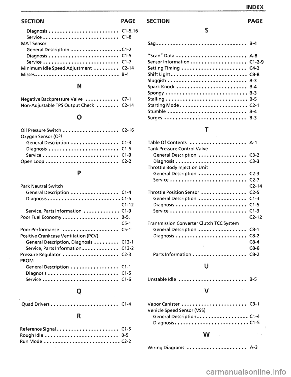
SECT ION PAGE
Diagnosis ......................... C1.5. 16
Service
........................... C1-8
MAT Sensor
General Description
.................. C1-2
Diagnosis
......................... C1-5
Service
........................... C1-7
Minimum
Idle Speed Adjustment ......... C2-14
Misses
.............................. B-4
Negative Backpressure Valve
............ C7-1
Non-Adjustable TPS Output Check
........ C2-14
Oil Pressure Switch
.................... C2-16
Oxygen Sensor
(02)
General Description ................. C1-3
Diagnosis ......................... C1-5
Service
........................... C1-9
Open Loop
.......................... C2-2
Park Neutral Switch
General Description
................. C1-4
Diagnosis
.......................... C1-5
C1-12
Service. Parts Information
............. C1-9
Poor Fuel Economy
.................... B.5.
C5- 1
Poor Performance
.................... C5-1
Positive Crankcase Ventilation (PCV)
General Description. Diagnosis
......... C13-1
Service. Parts Information
............. C13-2
Pressure Regulator
.................... C2-3
PROM General Description
................. C1-1
Diagnosis ......................... C1-5
Service
........................... C1-6
....................... Quad Drivers. C1-4
Reference Signal
...................... C1-5
Rough
Idle .......................... B-5
RunMode ........................... C2-2
SECTION PAGE
S
Sag ................................ B-4
"Scan" Data
......................... A-8
Sensor Information
.................... C1-2-9
Setting Timing
....................... C4-2
Shift Light
........................... C8-8
Sluggish
............................ B-3
Spark Knock
......................... B-4
Spongy
............................. 8-3
Stalling ............................. B-5
Starting Mode
........................ C2-1
Stumble
............................ B-4
Surges
............................. B-3
Table Of Contents
.................... A-1
Tank Pressure Control Valve
General Description
................. C3-2
Diagnosis
......................... C3-3
Throttle Body Injection Unit
General Description
................. C2-3
Service
........................... C2-7
C2- 14
Throttle Position Sensor
................ C2-5
General Description
................. C1-3
Diagnosis
......................... C1-5
Service
........................... C1-9
C2- 12
Transmission Converter Clutch TCC System
General Description
................. C8-1
Diagnosis
......................... C8-2
C8-4 C8-6
Parts Information
................... C8-2
Unstable
Idle ........................ B-5
....................... Vapor Canister C3-1
Vehicle Speed Sensor (VSS)
.................. General Description C1-4
Diagnosis
......................... 4.5
..................... Wiring Diagrams 8-3
Page 646 of 1825
DRIVEABILITY AND EMISSIONS 2.8L (VIN 5). 5.OL (VIN F) & 5.7L (VIN 8) 6E3-1
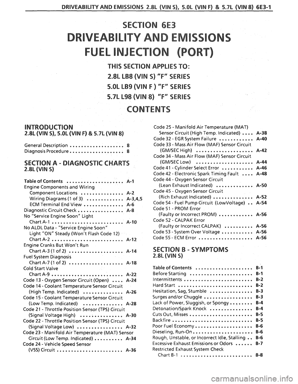
SECTION 6E3
TY AND EM
THIS SEC"T0N APPLIES TO:
2.8L LB8 (VlN S) "F" SERIES
5.OL LB9 (VIN F ) "F'" SERIES
5.7L L98 (VIN 8) ""F3"lES
CONTENTS
INTRODUCTION
2.8L (VIN 5). 5.OL (VIN F) & 5.7L (WIN 8)
General Description ................... 8
Diagnosis Procedure ................... 8
SECTION A . DIAGNOSTIC CHARTS
2.8L (VIN S)
Table of Contents .................... A-1
Engine Components and Wiring
Component Locations
............... A-2
Wiring Diagrams (1 of 3) ............. A.3.4. 5
ECM Terminal End View .............. A-6
Diagnostic Circuit Check ................ A-8
No "Service Engine Soon" Light
Chart A-I
......................... A-10
No ALDL Data . "Service Engine Soon"
Light "ON" Steady (Won't Flash Code 12)
Chart A-2
......................... A-12
Engine Cranks But Won't
.... Chart A-3 (1 of 2)
Fuel System Diagnosis Run ................ A-14
. ChartA-7(1 of
2) ................... A-18
Cold Start Valve
Chart A-9
......................... 8-22
. .... Code 13 Oxygen Sensor Circuit (Open) A-24
Code 14 . Coolant Temperature Sensor Circuit
. (High Temp Indicated) .............. A-26
Code 15 . Coolant Temperature Sensor Circuit
(Low Temp
. Indicated) .............. A-28
Code 2 1 . Throttle Position Sensor (TPS) Circuit
(Signal Voltage High)
........ , ...... A-30
Code 22 . Throttle Position Sensor (TPS) Circuit
(Signal Voltage Low)
......... , ...... A-32
Code 23 . Manifold Air Temperature (MAT) Sensor
. Circuit (Low Temp Indicated) .......... A-34
Code 24 . Vehicle Speed Sensor
(VSS) Circuit ....................... A-36
Code 25 . Manifold Air Temperature (MAT)
Sensor Circuit (High Temp
. Indicated) .... A-38
Code 32 . EGRSystem Failure ............ A-40
Code 33 . Mass Air Flow (MAF) Sensor Circuit
(GMISEC High) .................... A-42
Code 34 . Mass Air Flow (MAF) Sensor Circuit
(GMISEC Low) .................... A-44
Code 41 . Cylinder Select Error ........... A-46
Code 42 . Electronic Spark Timing Fault .... A-48
Code 44 . Oxygen Sensor Circuit
(Lean Exhaust Indicated)
............. A-50
Code 45 . Oxygen Sensor Circuit
(Rich Exhaust Indicated)
.............. A-52
Code 54 . Fuel Pump Circuit (Lowvoltage) . . A-54
Code 5 1 . PROM Error
(Faulty or Incorrect PROM)
............ A-56
Code 52 . CALPAK Error
(Faulty or Incorrect CALPAK)
.......... A-56
Code 53 . System Over Voltage ........... A-56
Code 55 . ECM Error ................... A-56
SECTION B . SYMPTOMS
2.8L (WIN 5)
Table of Contents .................... B-1
Before Starting ...................... B-1
Intermittents ........................ B-2
Hard Start .......................... 8-2
Hesitation. Sag. Stumble ............... 8-3
Surges and/or Chuggle ................. 8-3
Lack of Power. Sluggish. or Spongy ........ B-4
DetonationJSpark Knock ............... 6-4
Cuts Out. Misses ...................... 8-5
Backfire ............................ 8-5
Poor Fuel Economy .................... B-6
Dieseling. Run.On ..................... 8-6
Rough. Unstable. or lncorrect Idle. Stalling . . €3-6
Excess~ve Exhaust Emissions or Odors ...... 8-7
Restr~cted Exhaust System Check
Chart
B-I ......................... 8-63
Page 649 of 1825
6E3-4 2.8L (VIN S) . 5.OL (VIN F) & 5.7L (VIN 8) DRIVEABILITY AND EMISSIONS
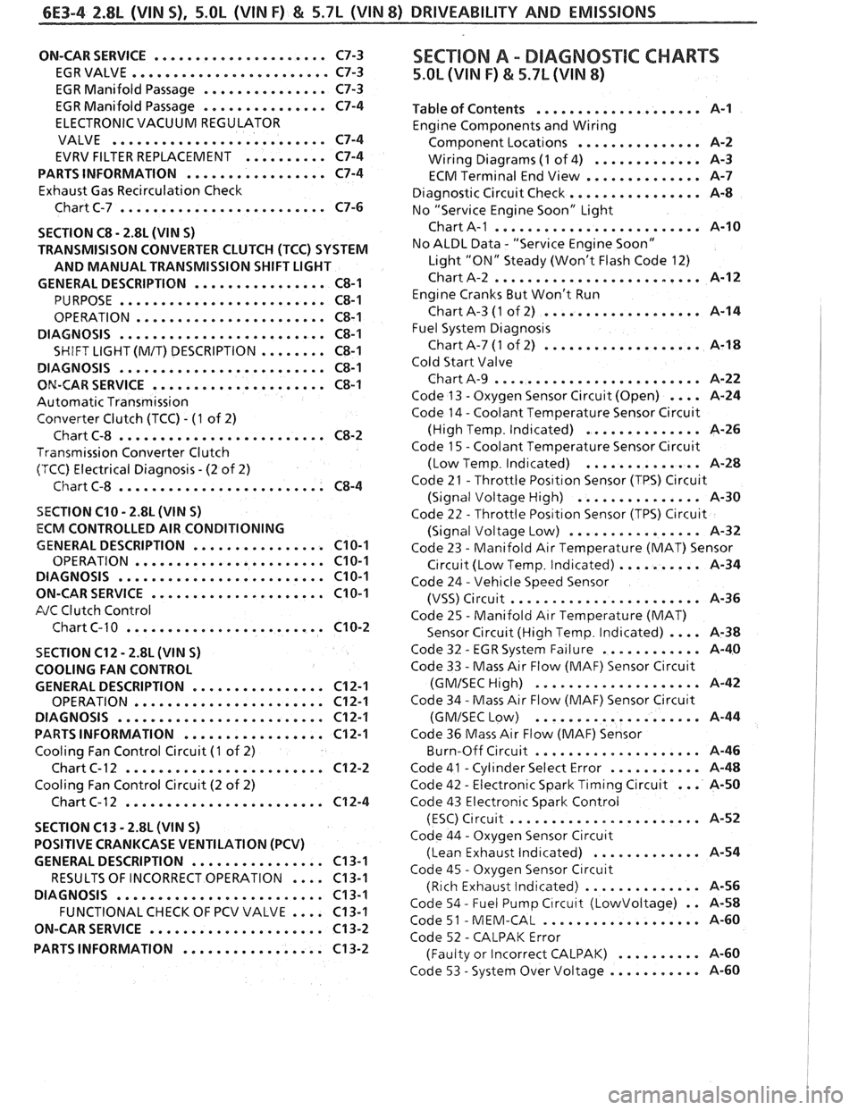
ON-CAR SERVICE ..................... C7-3
EGRVALVE
........................ C7-3
EGR Manifold Passage
............... C7-3
EGR Manifold Passage
............... C7-4
ELECTRONIC VACUUM REGULATOR
VALVE
.......................... C7-4
EVRV FILTER REPLACEMENT
.......... C7-4
PARTS INFORMATION
................. C7-4
Exhaust Gas Recirculation Check
Chart C-7
......................... C7-6
SECTION
C8 . 2.8L (VIN S)
TRANSMISISON CONVERTER CLUTCH (TCC) SYSTEM
AND MANUAL TRANSMISSION SHIFT LIGHT
GENERAL DESCRIPTION
................ C8-1
PURPOSE ......................... C8-1
OPERATION ....................... C8-1
DIAGNOSIS
......................... C8-1
SHIFT LIGHT (M/T) DESCRIPTION ........ C8-1
DIAGNOSIS
......................... C8-1
ON-CAR SERVICE ..................... C8-1
Automatic Transmission
Converter Clutch (TCC)
. (1 of 2)
Chart C-8
......................... C8-2
Transmission Converter Clutch
(TCC) Electrical Diagnosis
. (2 of 2)
Chart C-8
......................... C8-4
SECTION C10 . 2.8L (WIN S)
ECM CONTROLLED AIR CONDITIONING
GENERAL DESCRIPTION
................ C10-1
OPERATION ....................... C10-1
DIAGNOSIS ......................... C10-1
ON-CARSERVICE ..................... C10-1
FJC Clutch Control
Chart C-
1 0 ........................ C10-2
SECTION C12 . 2.8L (VlN S)
COOLING FAN CONTROL
GENERAL DESCRIPTION
................ C12-1
OPERATION ....................... C12-1
DIAGNOSIS
......................... C12-1
PARTS INFORMATION ................. C12-1
Cooling Fan Control Circuit (1 of 2)
Chart
C- 12 ........................ C12-2
Cooling Fan Control Circuit (2 of 2)
Chart C-12
........................ C12-4
SECTION C13
. 2.8L (WIN S)
POSITIVE CRANKCASE VENTILATION (PCV)
GENERAL DESCRIPTION
................ C13-1
RESULTS OF INCORRECT OPERATION
.... C13-1
DIAGNOSIS
......................... C13-1
FUNCTIONALCHECK OF PCV VALVE .... C13-1
ON-CAR SERVICE
..................... C13-2
PARTS INFORMATION
................. C13-2
SEC"T0N A . DIAGNOSTIC CHARTS
5.OL (VIN F) & 5.7L (VIN 8)
.................... Table of Contents A-1
Engine Components and Wiring
............... Component Locations A-2
Wiring Diagrams
(1 of 4) ............. A-3
ECM Terminal End View
.............. A-7
Diagnostic Circuit Check
................ A-8
No "Service Engine Soon" Light
......................... Chart A-1 A-10
No ALDL Data
. "Service Engine Soon"
Light "ON" Steady (Won't Flash Code 12)
Chart A-2
......................... A-12
Eng~ne Cranks But Won't Run
Chart A-3
(1 of 2) ................... A-14
Fuel System
Diagnos~s
Chart A-7 (1 of 2) ................... A-18
Cold Start Valve
Chart A-9
......................... A-22
Code 13
. Oxygen Sensor Circuit (Open) .... A-24
Code 14
. Coolant Temperature Sensor Circuit
(High Temp
. Indicated) .............. A-26
Code
1 5 . Coolant Temperature Sensor C~rcuit
. .............. (Low Temp Ind~cated) A-28
Code 21
. Throttle Pos~tlon Sensor (TPS) Circuit
(Signal Voltage High)
............... A-30
Code 22
. Throttle Pos~t~on Sensor (TPS) Circuit
................ (Signal Voltage Low) A-32
Code 23
. Manifold Air Temperature (MAT) Sensor
C~rcuit (Low Temp . Indicated) .......... A-34
Code 24
. Vehicle Speed Sensor
....................... (VSS) Circuit A-36
Code 25
. Manifold Air Temperature (MAT)
Sensor Circuit (High Temp
. Indicated) .... A-38
. ............ Code 32 EGR System Failure A-40
Code 33
. Mass Air Flow (MAF) Sensor Circuit
.................... (GMISECHlgh) A-42
Code 34
. Mass Air Flow (MAF) Sensor Circu~t
.................... (GMISEC Low) A-44
Code 36 Mass Air Flow
(MAF) Sensor
.. ..... ........... Burn-Off Circuit , , A-46
. ........... Code 41 Cyl~nder Select Error A-48
... . Code 42 Electronic Spark Timing Circuit A-50
Code 43 Electronic Spark Control
(ESC)
C~rcuit ....................... A-52
Code 44
. Oxygen Sensor Circu~t
(Lean Exhaust lnd~cated) ............. A-54
Code 45
. Oxygen Sensor Circuit
(Rich Exhaust Indicated)
.............. A-56
Code 54
. Fuel Pump C~rcuit (Lowvoltage) . . 14-58
. ................... Code 51 MEM-CAL A-60
Code 52
. CALPAK Error
.......... (Faulty or Incorrect CALPAK) A-60
. ........... Code 53 System Over Voltage A-60
Page 654 of 1825
DRIVEABILITY AND EMISSIONS f.8b (VIN S) 6E3-A-1
Cold Oxygen Sensor
The "Diagnostic Circuit Check" verifies the On some engines.
the oxygen sensor will cool off
system is functioning correctly . some special after only a short period of operation at idle . This will
considerations to keep in mind while making the put the system into "Open Loop" . To restore "Closed
"Diagnostic Circuit Check" are: Loop"
operation. run the engine
at part throttle
several minutes and accelerate from idle to part
Blocking Drive Wheels throttle a few times .
The vehicle drive wheels should always be blocked Basic Procedure
while checking the system . If you have not reviewed the basic information on
how to
use the diagnostic procedures. go to the
introduction of this section
.
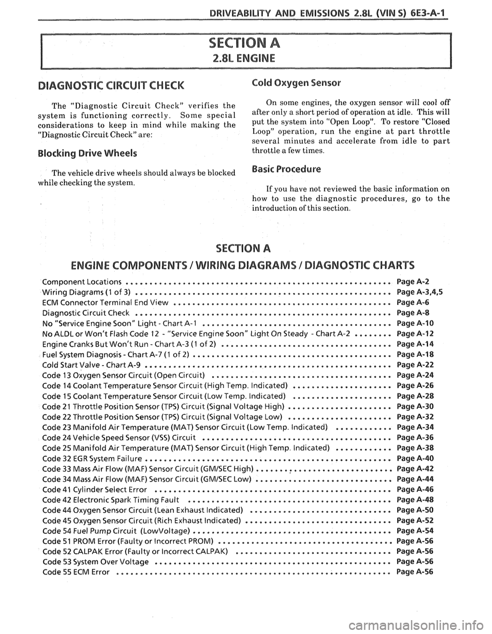
ENGINE COMPONENTS /WIRING DIAGRAMS / DIAGNOSTIC CHARTS
ComponentLocations ........................................................ PageA-2
Wiring Diagrams (1 of 3) ...................................................... Page A.3.4. 5
ECM Connector Terminal End View
.............................................. Page A-6
Diagnostic Circuit Check
...................................................... Page A-8
No "Service Engine Soon" bight
. Chart A-1 ........................................ Page A-10
No
ALBL or Won't Flash Code 12 . "Serv~ce Engine Soon" Light On Steady . Chart A-2 ........ Page A-12
. Engine Cranks But Won't Run Chart A-3 (1 of 2) .................................... Page 8-14
. Fuel System Diagnosis Chart A-7 (1 of
2) .......................................... Page A-18
Cold Start Valve
. Chart A-9 .................................................... Page A-22
Code 13 Oxygen Sensor Circuit (Open Circuit)
...................................... Page A-24
Code 14 Coolant Temperature Sensor Circuit (High Temp
. Indicated) ..................... Page A-26
Code 15 Coolant Temperature Sensor Circuit (Low Temp
. Indicated) ..................... Page A-28
Code 21 Throttle Position Sensor (TPS) Circuit (Signal Voltage High)
...................... Page A-30
Code 22 Throttle Position Sensor (TPS) Circuit (Signal Voltage Low)
...................... Page A-32
Code 23 Manifold Air Temperature (MAT) Sensor Circuit (Low Temp
. Indicated) ............ Page A-34
Code 24 Vehicle Speed Sensor (VSS) Circuit
........................................ Page A-36
Code
25 Manifold Air Temperature (MAT) Sensor Circuit (High Temp . Indicated) ............ Page A-38
Code 32
EGR System Failure .................................................... Page A-40
Code 33 Mass Air Flow (MAF) Sensor Circuit
(GMISEC High) ............................. Page A-42
Code 34 Mass Air Flow (MAF) Sensor Circuit
(GMISEC bow) ............................. Page 8-44
Code
41 Cylinder Select Error .................................................. Page A-46
Code 42 Electronic Spark Timing Fault
................... .... .................... Page 8-48
Code 44 Oxygen Sensor Circuit (Lean Exhaust Indicated)
.............................. Page A-50
Code
45 Oxygen Sensor Circuit (Rich Exhaust Indicated) ............................... Page A-52
Code 54 Fuel Pump Circuit
(Lowvoltage) .......................................... Page A-54
Code
51 PROM Error (Faulty or Incorrect PROM) ..................................... Page A-56
Code 52 CALPAK Error (Faulty or Incorrect CALPAK)
................................. Page 44-56
Code 53 System Over Voltage .................................................. Page A-56
Code55ECMError ............................O.~o.~.~e.~e~e.~e....... .. PageA-56