1988 PONTIAC FIERO wiring diagram
[x] Cancel search: wiring diagramPage 1040 of 1825
HYDRAULIC DIAGNOSIS 700-R4-51
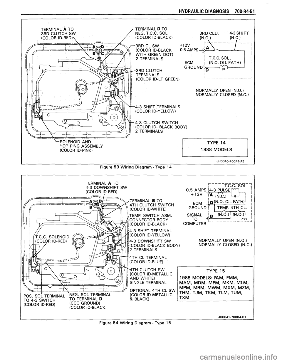
OLEN NO ID AND "0" RING ASSEMBLY
(COLOR ID-PINK) 1988 MODELS
Figure
53 Wiring Diagram - Type 14
TERMINAL A TO
4-3 DOWNSHIFT SW
(COLOR ID-RED)
TERMINAL
B TO
4TH CLUTCH SWITCH
(COLOR ID-WHITE)
TEMP. SWITCH ASM.
CONNECTOR BODY
(COLOR ID-BLACK)
4-3 SHIFT TERMINAL
(COLOR ID-YELLOW)
4-3 DOWNSHIFT SW
(COLOR ID-BLACK BOD
2 TERMINALS
4TH
CL TERMINAL
(COLOR ID-BLUE)
4TH CLUTCH SW
(COLOR ID-METALLIC
OPTIONAL 4TH CL SW
POS, SO[ TERMINAL 'NEG. SOL TERMINAL (COLOR
ID-METALLIC
TO TERMINAL D 4-3 (CCC GROUND) & BLACK)
IDFRED' (COLOR ID-BLACK) NORMALLY
OPEN
(N.O.)
Y) NORMALLY CLOSED (N.C.)
TYPE 15
1988
MODELS: FAM, FMM,
MAM, MDM, MFM, MKM, MLM,
MPM, MRM, MWM, MXM, MZM,
THM, TJM, TKM, TLM, TUM,
TXM
JH0041-700R4-R1
Figure 54 Wiring Diagram - Type 15
Page 1041 of 1825
70044-52 HYDRAULIC DIAGNOSIS
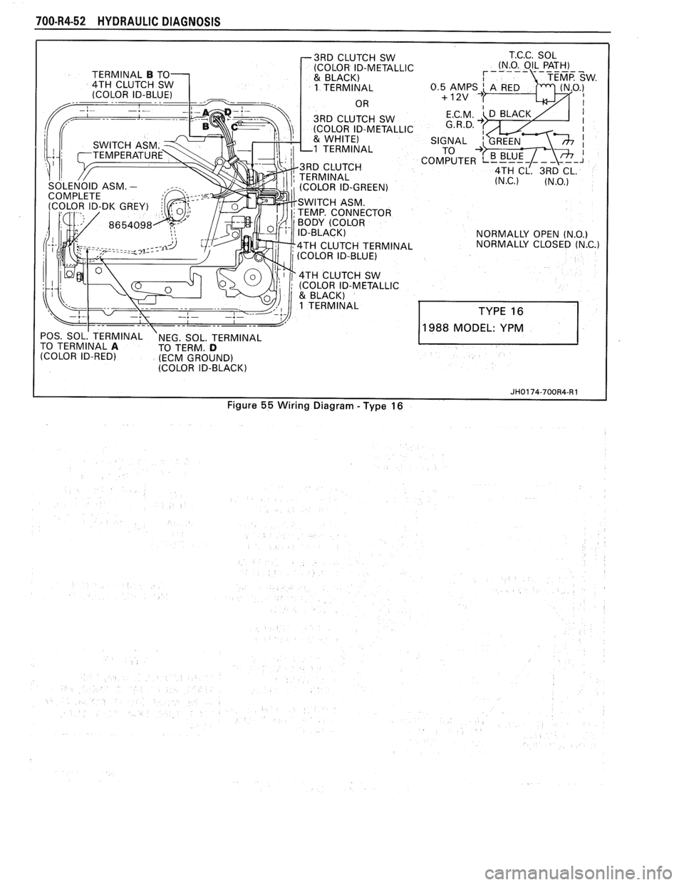
r3RD CLUTCH SW
POS. SOL.' TERMINAL NEG. SOL. TERMINAL
TO TERMINAL A TO TERM. D (COLOR ID-RED) (ECM GROUND)
(COLOR ID-BLACK) T.C.C.
SOL
(N.O. OIL PATH)
NORMALLY OPEN
(N.O.) NORMALLY CLOSED (N.C.)
988 MODEL: YPM
JH0174-700R4-R 1
Figure 55 Wiring Diagram - Type 16
Page 1050 of 1825
TORQUE CONVERTER CLUTCH (TCC)
DIAGNOSIS
To properly diagnose the Torque Converter
Clutch (TCC) system, perform all electrical
testing first and then the hydraulic testing. Refer
to the Torque Converter Section
6E2-C8 for
additional information.
The TCC is applied by fluid pressure which is
controlled by a solenoid located inside the Automatic
Transmission assembly. The solenoid is energized or
released by making or breaking an electrical circuit
through a combination of switches and sensors.
TCC Electrical Diagnosis
e For electrical diagnosis of TCC, refer to the
specific vehicle section in Section
8A, Electrical
Diagnosis.
e For diagnosis of emission control related
components of TCC, Refer to the specific section
of
6E, Driveability and Emissions.
e For the diagnosis of TCC Hydraulic Controls,
refer to the Procedure and Wiring Diagrams
provided in this section.
Functional Check Procedure
rn Inspect
1. Install a tachometer
2. Operate the vehicle until proper operating
temperature is reached
3. Drive vehicle at 50-55 mph (80-88 Km/h) with
light throttle (road load)
4. Maintaining throttle lightly touch the brake
pedal and check for a slight bump when the TCC
releases and a slight increase in engine RPM.
5. Release the brake, slowly accelerate and check for
a re-apply of the converter clutch and a slight
decrease in engine RPM.
Preliminary Checking Procedure
The purpose of the preliminary checking
procedure is to isolate external (electrical) problems
from internal (electrical or mechanical) ones.
Important
e Use only a scale type ohmmeter. High impedance
type ohmmeters and those with a digital readout
will not work.
e An ALCL scanner may be used to verify the
electrical circuit. Remember, a completed circuit
does not indicate that the solenoid will apply.
e Do not bench test using an automotive type
battery. Accidentally crossed wires will damage
the internal diodes of the TCC solenoid.
HYDRAULIC DIAGNOSIS 700-R4-61
External Controls
rn Inspect
e Connect voltmeter between transmission
connector and ground.
e Turn key "ON"
e If 0 or low voltage is found, refer to Sections 6E
and 8A for electrical diagnosis.
e If 12 volts are present at the connector, refer to
the TCC hydraulic diagnosis.
TORQUE CONVERTER EVALUATION
Torque Converter Stator
The Torque Converter Stator roller clutch can
have one of two different type malfunctions:
A. Stator Assembly freewheels in both
directions.
B. Stator Assembly remains locked up at all
times.
Condition A-Poor Acceleration Low Speed
The vehicle tends to have poor acceleration from
a standstill. At speeds above 30-35 mph (50-55
km/h),
the car may act normal. If poor acceleration is noted,
it should first be determined that the exhaust system
is not blocked, the engine timing is correct and the
transmission is in first
(1st) gear when starting out.
If the engine freely accelerates to high
r.p.m. in
"NEUTRAL" (N), it can be assumed that the engine
and exhaust system are normal. Checking for poor
performance in "Drive" and Reverse will help
determine if the stator is freewheeling at all times.
Condition B-Poor Acceleration High Speed
Engine r.p.m. and car speed limited or restricted
at high speeds. Performance when accelerating from a
standstill is normal. Engine may over-heat. Visual
examination of the converter may reveal a blue color
from over-heating.
If the converter has been removed, the stator
roller clutch can be checked by inserting a finger into
the splined inner race of the roller clutch and trying to
turn the race in both directions. The inner race should
turn freely clockwise, but not turn or be very difficult
to turn counterclockwise.
The Converter Should Be Replaced If:
e Leaks externally, such as at the hub weld area.
e Converter has an imbalance which cannot be
corrected. (Refer to Converter Vibration Test
Procedure).
e Converter is contaminated with engine coolant
containing antifreeze.
The Converter Should Not Be Replaced If:
e The oil has an odor, is discolored, and there is no
evidence of metal or clutch facing particles.
e The threads in one or more of the three converter
bolt holes are damaged.
- Correct with thread insert. (Refer to Section
6A).
Page 1056 of 1825
AUTOMA"PI&: TRANSMISSION 780-R4-5
5. Case extension bolts (37)
and case extension (36)
6. Extension seal ring (35)
7. Output
shaft sleeve (690) and output shaft o-ring
seal (691)
- Not all models use an output shaft sleeve
and seal
a Remove or Disconnect (Figures 75)
Models with Mechanical Speedometer
1. Speedometer drive gear
(689) and clip (688)
- push tab of retaining clip and tap
speedometer gear off the output shaft.
- use care not to damage the speedo gear
Valve Body and Wiring Harness
Remove or Disconnect (Figures 76, 77)
1. Screws (74), oil
pan (73), and gasket (72).
2. Oil filter
(71) and filter seal (70).
- Filter seal may be stuck in the case
3. Outside
electrical connector (33) and o-ring seal
(34).
4. Electrical connections from switches.
- refer to wiring diagrams in the Hydraulic
Diagnosis Section for specific model
applications
5. Solenoid bolts
(51) and solenoid assembly (50)
with o-ring seal (49) and wiring harness.
6. Accumulator cover bolts (63) and 1-2
accumulator cover and pin assembly (62).
7. 1-2 accumulator piston (61) and seal (60).
8. Spring (59).
Remove or Disconnect (Figures 78,99,88 and 81)
1. Bolt (75) and manual detent spring assembly
(709).
2. Electrical wire clips (66) and tube clamps (97).
3. Auxiliary valve tube (96).
4. Wiring harness retaining washer (A) and the
filter retainer clips
(87).
5. Bolts (69) and T.V. lever and bracket assembly
(65)
6. T.V. link (64)
Remove or Disconnect (Figures 78,88,8'1 and 82)
1. Remaining valve body bolts (69)
2. Manual valve link (705)
3. Control valve assembly (67)
4. Bolts
(374-376), auxiliary valve body (377), and
check
ball (55)
5. Spacer plate (56) and spacer plate gaskets (88 and
89)
6. Check balls (55 and 91) spring (54), piston (52),
sea1 (53) and pin
- Three checkballs are located under the
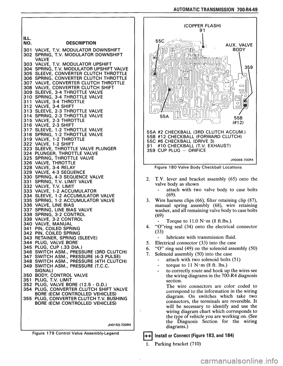
valve body, one in the auxiliary valve body
and four are located in the case. The large
copper flash colored ball is
# 10 check ball
(9 1)
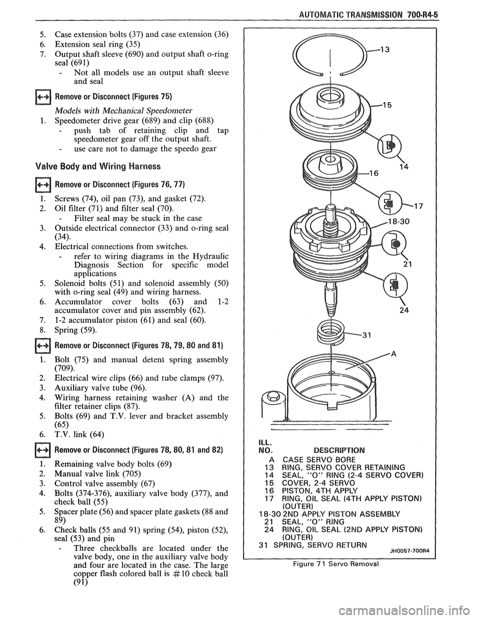
ILL.
NO.
A
13 14
15 16
17
DESCBPlPT!ON
CASE SERVO BORE
RING,
SERVO COVER RETAINING
SEAL, "0" RING (2-4 SERVO COVER)
COVER, 2-4 SERVO
PISTON, 4TH APPLY
RING,
OIL SEAL (4TH APPLY PISTON) (OUTER)
18-30 2ND AP'PLY PISTON ASSEMBLY 21 SEAL, "0" RlNG
24 RING, OIL SEAL (2ND APPLY
PISTON)
(OUTER) 31 SPRING, SERVO RETURN JH0057-700R4
Figure 7 1 Servo Removal
Page 1100 of 1825
AUTOMATIC TRANSMISSION 700-R4-49
--
NO. DESCRIPTION I 301 VALVE, T.V. MODULATOR DOWNSHIFT
302 SPRING, T.V. MODULATOR DOWNSHIFT
VALVE
303 VALVE, T.V. MODULATOR UPSHIFT
304 SPRING, T.V. MODULATOR UPSHIFT VALVE
305 SLEEVE, CONVERTER CLUTCH THROTTLE
306 SPRING, CONVERTER CLUTCH THROTTLE
307 VALVE, CONVERTER CLUTCH THROTTLE
308 VALVE, CONVERTER CLUTCH SHlFT
309 SLEEVE, 3-4 THROTTLE VALVE
3 10 SPRING, 3-4 THROTTLE VALVE
31 1 VALVE, 3-4 THROTTLE
312 VALVE, 3-4 SHlFT
31 3 SLEEVE, 2-3 THROTTLE VALVE
314 SPRING, 2-3 THROTTLE VALVE
31
5 VALVE, 2-3 THROTTLE
31 6 VALVE, 2-3 SHlFT
31 7 SLEEVE, 1-2 THROTTLE VALVE
31
8 SPRING, 1-2 THROTTLE VALVE
31 9 VALVE, 1-2 THROTTLE
322 VALVE, 1-2 SHlFT
323 SLEEVE, THROTTLE VALVE PLUNGER
324 PLUNGER, THROTTLE VALVE
325 SPRING, THROTTLE VALVE
326 VALVE, THROTTLE
328 VALVE, 3-4 RELAY
329 VALVE, 4-3 SEQUENCE
330 SPRING, 4-3 SEQUENCE VALVE
331 SPRING, T.V.
LIMIT VALVE
332 VALVE, T.V.
LIMIT
333 VALVE, 1-2 ACCUMULATOR
334 SLEEVE, 1-2 ACCUMULATOR VALVE
335 SPRING, 1-2 ACCUMULATOR VALVE
336 VALVE,
LlNE BlAS
337 SPRING, LlNE BlAS VALVE
338 SPRING, 3-2 CONTROL
339 VALVE, 3-2 CONTROL
340 VALVE, MANUAL
341 PIN, COILED SPRING
342 PIN, COILED SPRING
343 RETAINER, SPRING (SLEEVE)
344 PLUG, VALVE BORE
345 PLUG, CUP
(-33 DIA.)
346 SWITCH ASM., PRESSURE (3RD CLUTCH)
347 SWITCH ASM., PRESSURE (4-3 PULSE)
348 SWITCH ASM., PRESSURE
(4TH CLUTCH)
349 SWITCH ASM., PRESSURE
(T.C.C.
SIGNAL)
350 BODY, CONTROL VALVE
351 PLUG, T.V. LIMIT
352 PLUG, VALVE BORE (12.5
- O.D.)
354 PLUG, CONVERTER CLUTCH SHlFT VALVE
BORE
(ECM CONTROLLED VEHICLES)
355 PLUG, CONVERTER CLUTCH T.V. BUSHING
BORE
(ECM CONTROLLED VEHICLES)
Figure 179 Control Valve Assembly-Legend
(COPPER FLASH) 9 1
55A
#2 CHECKBALL (3RD CLUTCH ACCUM.)
558 #12 CHECKBALL (FORWARD CLUTCH)
55C #6 CHECKBALL (DRIVE 3) 91 #10 CHECKBALL (T.V. EXHAUST)
359 CUP PLUG - ORIFICE
Figure 180 Valve Body Checkball Locations
2. T.V. lever and bracket assembly (65) onto the
valve body as shown
- attach with two valve body to case bolts
(69).
3. Wire harness
clips (66), filter retaining clip (87),
manual spring assembly (68), wire retaining
washer, and all remaining valve body to case bolts
(69) - Torque to 11.0 Nam (8 ft.lbs.).
4. "0"ring seal (34) onto the electrical connector
(33)
- lubricate with transmission fluid.
5. Electrical connector
(33) into the case
6.
"0" ring seal (49) on the solenoid assembly (50)
7. Solenoid assembly (50) into the case
- attach with two solenoid bolts (51)
- torque to 11 N . m (8 ft. lbs.)
- to correctly route and hook up the wires see
the wiring diagrams in the 700-R4 diagnosis
section.
The wire connectors are color coded to
correspond to the information in the wiring
diagram. On switches which take two
connectors, the terminals are reversible.
It
will be necessary to identify and use the
wiring diagram chart which corresponds to
the type
of vehicle you are working on. (See
the Diagnosis Section for the wiring
diagrams.)
Install or Connect (Figure 183, and 184)
1. Parking bracket (710)
Page 1122 of 1825
AUTOMATIC TMNSMISSION ON-VEHICLE SERVICE 7A1-3
e Propeller shaft oil seal worn or damaged
o Governor cover
e Line pressure pipe plug loose
@ Porous casting
3. Leak at converter end:
Converter seal damaged
- Seal lip cut. (Check converter hub for
damage.)
- Bushing moved forward and damaged
- Garter spring missing from seal
o Converter leak in weld area. (Refer to
Torque Converter.)
Porous casting (Case or pump)
4. Fluid comes out vent pipe or fill tube:
Over-filled
Water or coolant in fluid. Fluid will appear
milky.
e Case porous
e Incorrect fluid level indicator
e Plugged vent
e Drain back holes plugged
Mispositioned oil pump to case gasket (if
equipped)
Case Porosity Repair
1. Clean the leak area with solvent and air dry.
CAUTION: Epoxy adhesive may cause
skin irritations and eye damage. Read
and follow all information on the
container label as provided by the
manufacturer.
2. Mix a sufficient amount of epoxy adhesive,
# 1052533, or equivalent, following the
manufacturer's recommendations.
3. While the transmission case is hot, apply epoxy
adhesive with a clean, dry soldering acid brush.
4. Allow the epoxy adhesive to cure for three hours
before starting the engine.
5. Repeat fluid leak diagnosis procedures.
TORQUE CONVERTER CLUTCH ELECTRICAL
CONTROLS
The Torque Converter Clutch (TCC) system uses
controls that are internal as well as external to the
transmission. For internal control components of the
TCC system, refer to the I-Iydraulic Diagnosis Section
for for wiring diagrams and switch locations.
The external control components of the TCC
system include:
1. Brake Release Switch - To avoid stalling the
engine when braking, the converter clutch is
released any time the brakes are applied.
2. Electronic Control ModuOe - Receives input
signals and grounds TCC solenoid to apply clutch
when proper operating conditions are met.
3. Throttle Position Sensor - Sends throttle
position information to Electronic Control
Module.
4. Vacuum Sensor - Sends engine vacuum (load)
information to Electronic Control Module.
5. Vehicie Speed Sensor - Sends vehicle speed
information to Electronic Control Module.
6. Coolant Temperature Sensor - Sends engine
coolant temperature information to Electronic
Control Module.
TORQUE CONVERTER CLUTCH DIAGNOSIS
To properly diagnose the Torque Converter
Clutch (TCC) system perform all electrical testing first
and then the hydraulic testing. Refer to the appropriate
Driveability and Emissions Section (6E) for additional
Torque Converter Clutch Information
ON-VEHICLE SERVICE
SI-IIFT CONTROL CABLE
Remove or Disconnect (Fig. 1)
1. Negative battery cable.
2. Raise car, see Section OA.
3. Cable attachments at transmission.
4. Lower car.
5. Console, see Section
8C.
6. Cable at control lever and base.
7. Cable from floor.
install or Connect
1. Cable to floor.
2. Cable at base and control lever.
3. Console, see Section 8C.
4. Place control lever in "NEUTRAL"
5. Raise car.
6. Cable attachments at transmission.
7. Adjust cable.
8. Lower car.
9. Negative battery cable.
Adjust (Fig. 1)
1. Place control lever in "N" (Neutral).
2. Raise car, see Section 0.4.
3. Loosen cable
attachment at shift lever.
4. Rotate shift lever "clockwise" to park detent and
then back to neutral.
5. Tighten cable attachment.
15
N-m (11 lbs. ft.)
Important
Levg must be held out of "PARK" when
torquing nut.
6. Lower car.
7. Check cable adjustment by rotating control lever
thru the detents.
Remove or Disconnect (Fig. 2)
1. Negative battery cable.
2. Console, see Section 8C.
3. Cable at control lever and base.
Page 1209 of 1825
POWER DISTRIBUTION
CIRCUIT OPERATION
Electrical power for the car is provided by the
Generator when the engine is running. The
schematic diagram shows how each circuit gets
its power. For more details about the Gener-
ator, and connections to the Battery and
Starter, see Starter and Charging System, Sec-
tion
8A-30.
The car's Power Distribution System con-
sists of Fusible Links, Fuses, Circuit Breakers,
the Light Switch and the Ignition Switch. Fusi-
ble Links are short pieces of wire to which they
supply power. They are covered with a special
high-temperature insulation. When conducting
a high current, the Fusible Link will melt and
stop current flow. They are designed to protect
the car's electrical system from electrical
shorts where it is not protected by the Circuit
Breakers and Fuses. See Fuse Block Details
and Light Switch Details for complete wiring to
the first component in each circuit.
The Ignition Switch has six positions, five of
which have detents. The BULB TEST position
is after the RUN position and just before the
START position. BULB TEST does not have a
detent. As shown in the schematic, circuits
which are supplied from the Ignition Switch are
On (Hot) for different switch positions. Indi-
vidual schematics show their fuses supplied
from headings such as "Not In Run. "The head-
ing corresponds to the Ignition Switch position
in which power is On.
Page 1602 of 1825
LIGHTING SYSTEMS AND HORNS 8B-3
HORNS the steering wheel sounds the horn by closing the horn
relay (in the convenience center behind the instrument
panel, to the right of the steering column). The horns
The holm(§) are mounted behind the front fascia use a solenoid-operated diaphragm to generate sound.
on the driver's side. $ushing the pad in the center of See Section 8A-40 for wiring and circuit information.
ON-CAR SERVICE
Wiring diagrams and other diagnosis information
is given in Section
8A. Information on properly
repairing wiring harnesses, connectors, etc., is on
8A-5.
Most lighting problems are caused by loose
connectors, open or shorted wiring, burned-out bulbs,
bad switches, inadequate ground or blown fuses. Many
of these require only replacement of a defective part.
When replacing a part that requires a special procedure
(such as a lens and housing assembly sealed together),
follow the instructions normally included in the
replacement parts package.
When removing a part that requires special
sealing items (such as sealing washers), be sure to
reinstall those items when replacing the part. Also, if
any body sealing items (grommets, etc.) are disturbed,
be sure to repair them so the passenger compartment
remains properly sealed.
EXTERlOR LIGHTS
BACK-UP LIGHTS
Fig. 8B-8
Replacement Bulb: Trade No. 1156, 32
Candlepower
To replace a back-up light bulb, see "Rear
Tail/Stop/Turn Signal Lights9' in this section. For
information on the back-up light switch on the
transmission, see Section
7.
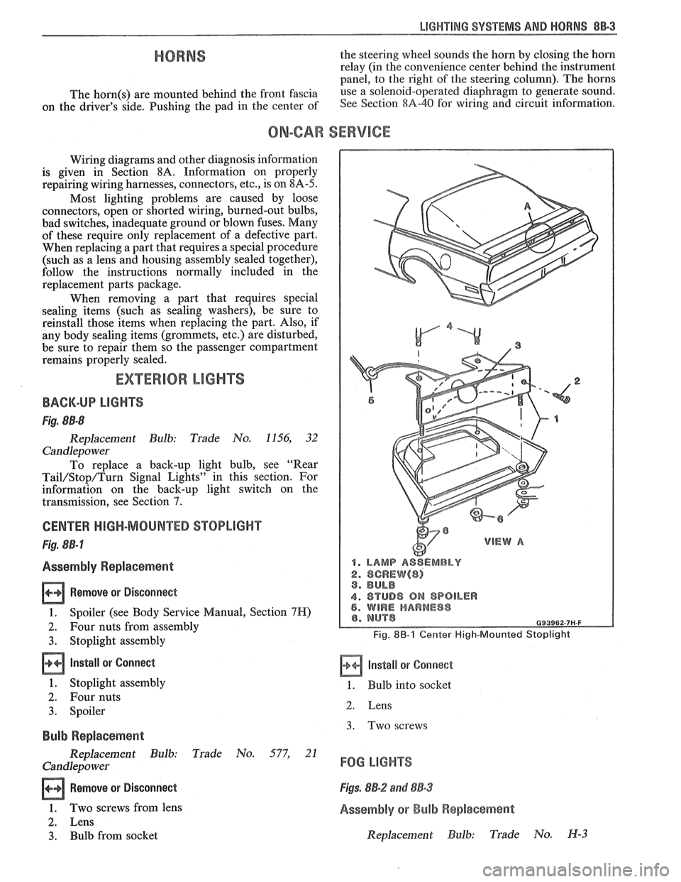
CENTER HIGH-MOUNTED STOPLIGHT
Fig. 8B-7
Assembly Replacement
Remove or Disconnect
1. Spoiler (see Body Service Manual, Section 7H)
2. Four nuts from assembly
3. Stoplight assembly
Install or Connect
1. Stoplight assembly
2. Four nuts
3. Spoiler
Bulb Replacement
Replacement Bulb: Trade No. 577, 21
Candlepo wer
Remove or Disconnect
1. Two screws from lens
2. Lens
3. Bulb from socket
1. LAMP ASSEMBLY
2. SCREW($) 3. BULB
4. STUD8 ON SPOILER 5. WIRE HARNESS
Fig. 8B-1 Center High-Mounted Stoplight
Install or Corrnect
1. Bulb into socket
2. Lens
3. Two screws
FOG LIGHTS
Figs. 8B-2 and 88-3
Assembly or Bulb Replacement
Replacement Bulb: Trade No. H-3