1988 PONTIAC FIERO wiring
[x] Cancel search: wiringPage 2 of 1825
1988
SER
This manual applies to the 1988 Pontiac Firebird Models.
It contains the latest product information available at the
time of publication approval. lnformation pertaining to
the operation of the vehicle is contained in the Owner's
Manual which accompanies each vehicle. The right is
reserved to make changes at any time without notice.
Any references to brand names in this manual is intended
merely as an example of the types of
lubricant% tools,
materials, etc, recommended for use in servicing 1988
Pontiac Models. In all cases, an equivalent may be used.
PONTIAC DIVISION
GENERAL
MOTORS CORPORATION
PONTIAC, MICHIGAN 48053
1987 General Motors Corp. All Rights Reserved.
No part of this publication may be reproduced, stored in any
retrieval system or transmitted in any form or by any means,
including but not limited to electronic, mechanical,
photocopying, recording or otherwise, without the prior written
permission of General Motors Corp. This includes all text,
illustrations, tables and charts.
S-881 OF 9-87 Printed in Canada
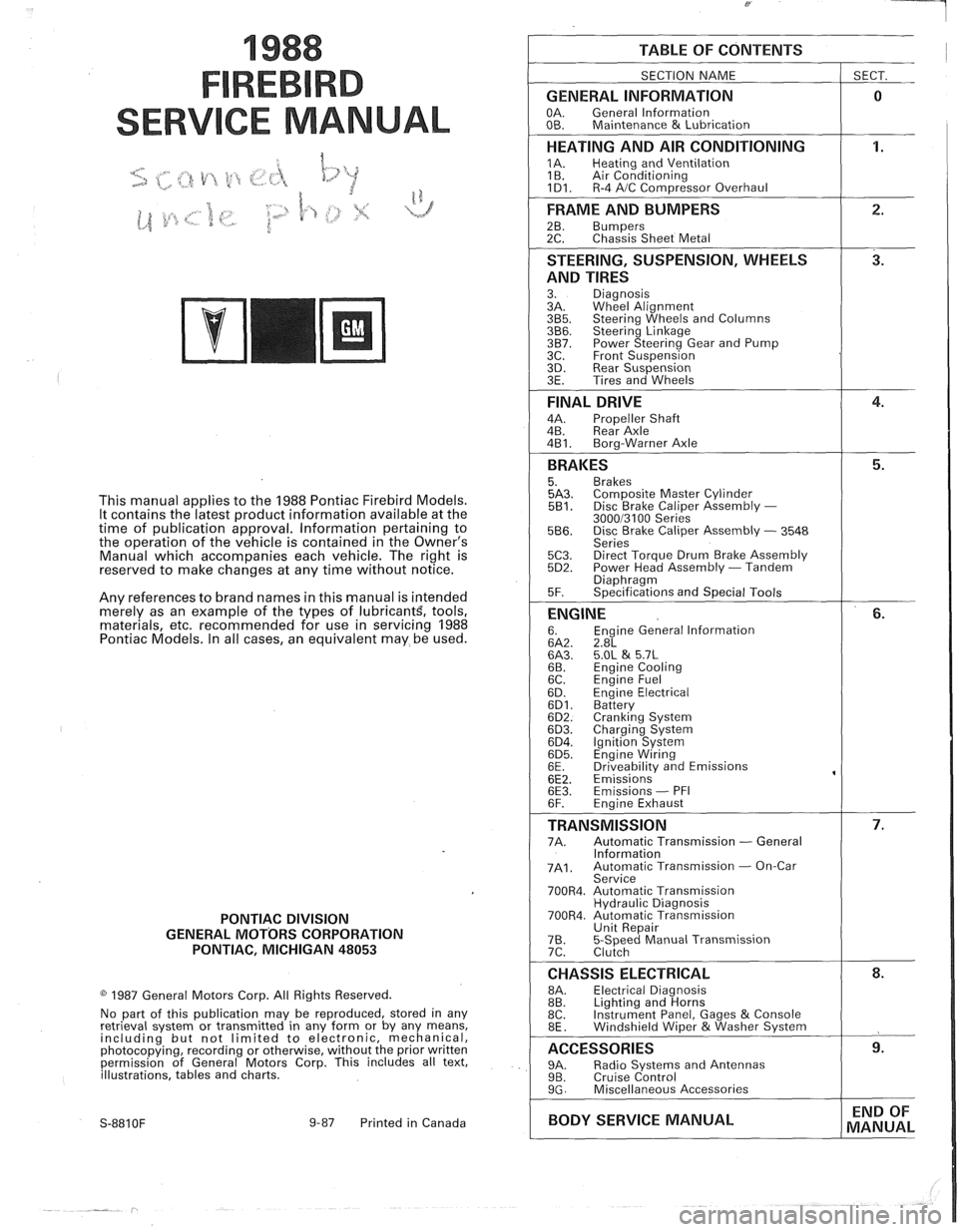
TABLE OF CONTENTS
SECTION NAME
GENERAL INFORMATION
OA. General lnformation
OB. Maintenance & Lubrication
1 SECT.
HEATING AND AIR CONDITIONING
1A. Heating and Ventilation
1 B. Air Conditioning
1D1. R-4 AIC Com~ressor Overhaul
FRAME AND BUMPERS
2B. Bumpers 2C. Chassis Sheet Metal
STEERING, SUSPENSION, WHEELS
AND TIRES
3. Diagnosis
3A. Wheel Alignment
3B5. Steering Wheels and Columns 3B6. Steering Linkage 3B7. Power Steering Gear and Pump
3C. Front Suspension
3D. Rear Suspension
3E. Tires and Wheels
FINAL DRIVE
4A. Propeller Shaft
4B. Rear Axle
4B1. Bora-Warner Axle
BRAKES 5. Brakes 5A3. Comoosite Master Cvlinder 5B1. Disc r rake Caliper ~ssembly - 300013100 Series 5B6. Disc Brake Caliper Assembly - 3548
Series
5C3. Direct Torque Drum Brake Assembly 5D2. Power Head Assembly - Tandem Diaohraam 5F. ~~ecifications and Special Tools
ENGINE 6. Engine General lnformation 6A2. 2.8L 6A3. 5.OL & 5.7L 6B. Engine Cooling
6C. En~ine Fuel
6D. ~ngine Electrical 6D1. Battery 6D2. Cranking System 6D3. Charging System 6D4. Ignition System 6D5. Engine Wiring
6E. Driveabilitv and Emissions
6E2. ~missions' 6E3. Emissions - PFI
6F. Engine Exhaust
TRANSMISSION 7A. Automatic Transmission - General
lnformation
7A1. Automatic Transmission - On-Car
Service
700R4. Automatic Transmission Hydraulic Diagnosis
700R4. Automatic Transmission Unit Repair
76. 5-Speed Manual Transmission
7C. Clutch
CHASSIS ELECTRICAL 8A. Electrical Diagnosis
8B. Lighting and Horns
8C. Instrument
Panel, Gages
& Console
8E. Windshield Wiper &Washer System
ACCESSORIES 9A. Radio Systems and Antennas 9B. Cruise Control 9G. Miscellaneous Accessories
I BODY SERVICE MANUAL END
OF
MANUAL
Page 33 of 1825
----
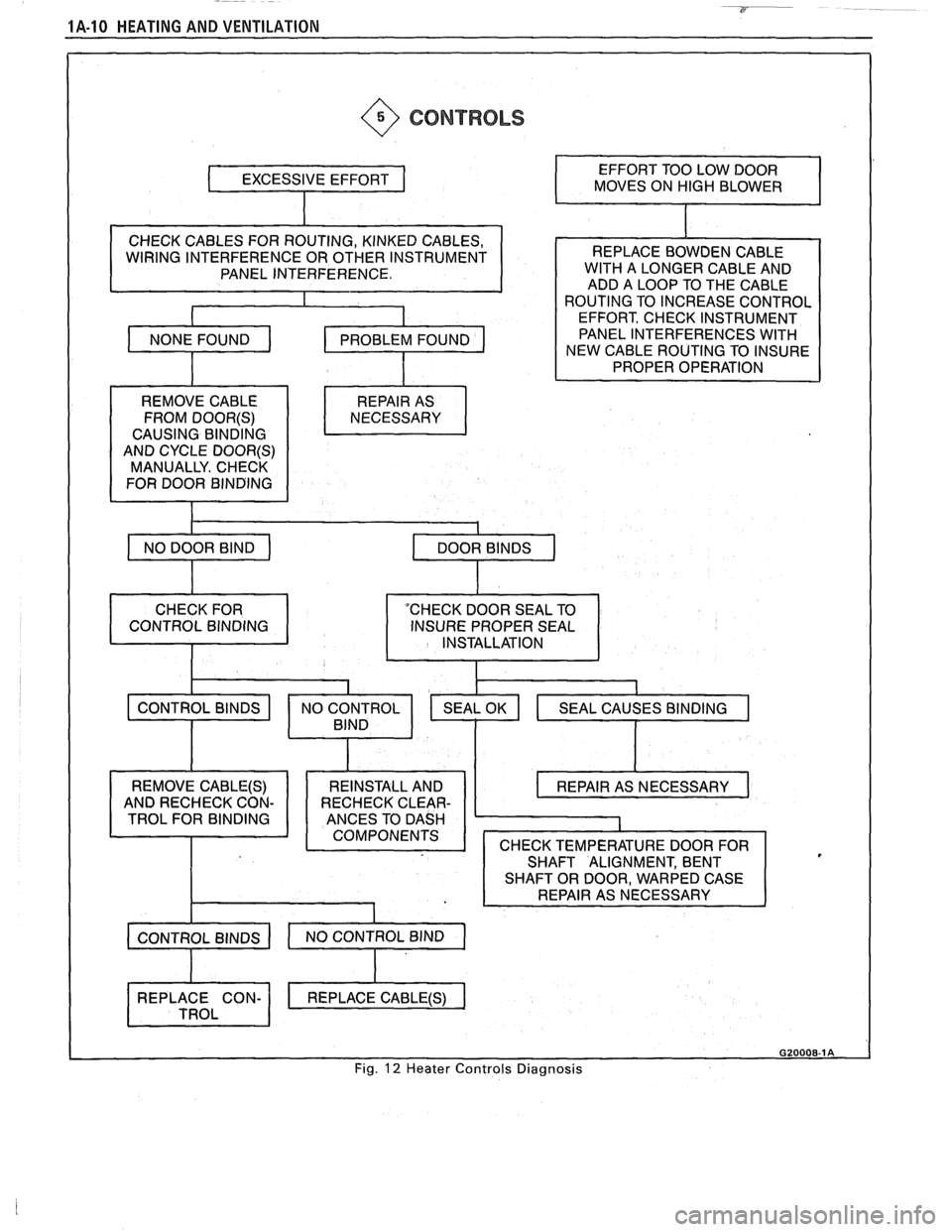
1A-10 HEATING AND VENTILATION
@ CONTROLS
CHECK CABLES FOR ROUTING, KINKEC CABLES,
WIRING INTERFERENCE OR OTHER INSTRUMENT
PANEL INTERFERENCE.
REMOVE CABLE FROM
DOOR(S)
CAUSING BINDING
AND CYCLE
DOOR(§)
MANUALLY. CHECK
FOR DOOR BINDING MOVES
ON
HIGH BLOWER
WlTH A LONGER CABLE AND
ADD A LOOP TO THE CABLE
ROUTING TO INCREASE CONTROL
EFFORT, CHECK INSTRUMENT
PANEL INTERFERENCES
WlTH
NEW CABLE ROUTING TO INSURE
PROPER
OPERATI
INSTALLATION
I
SEAL OK
SHAFT ALIGNMENT, BENT
Fig. 12 Heater Controls Diagnosis
Page 36 of 1825
HEATING AND VENTILATION 1.4-1 3
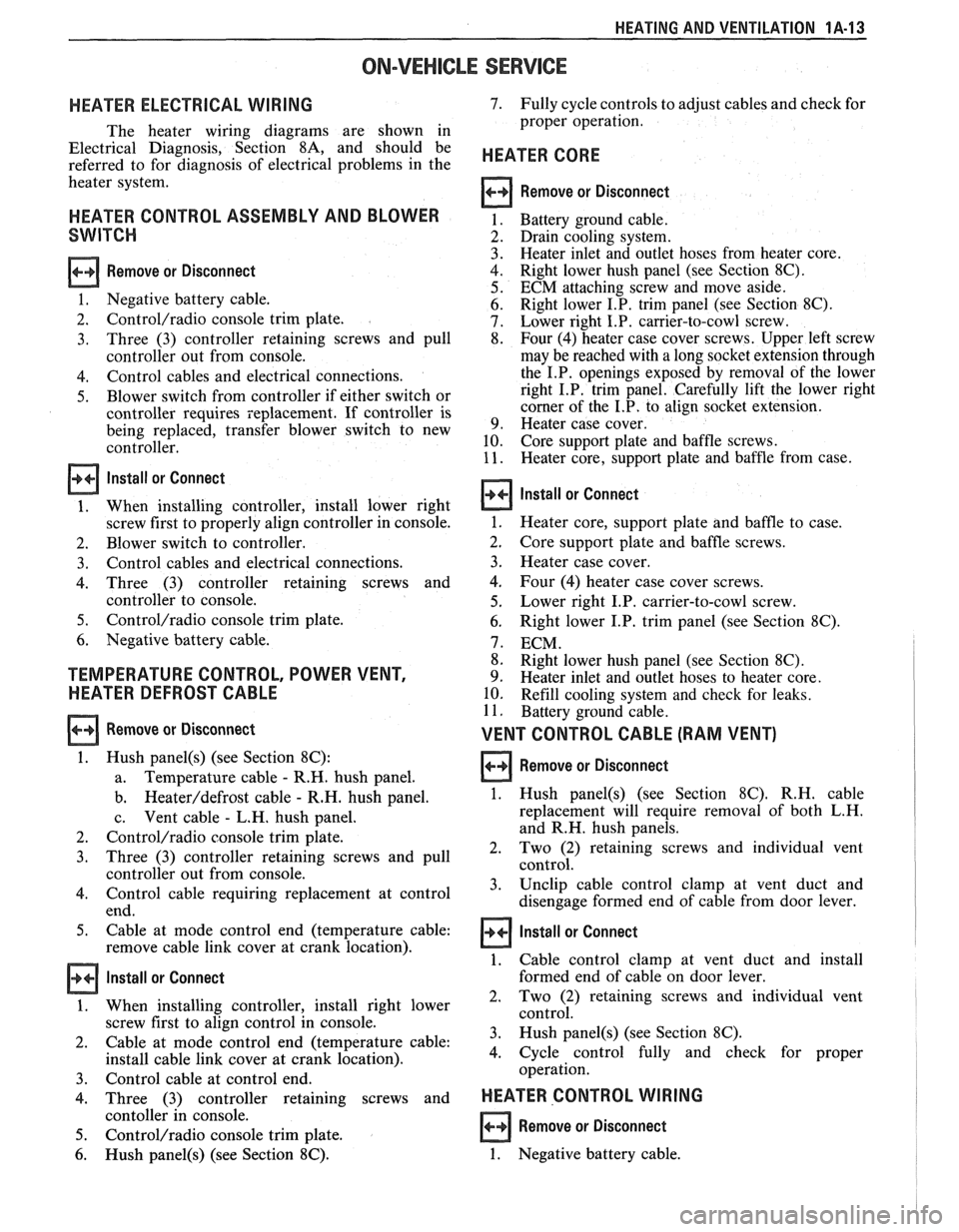
ON-VEHICLE SERVICE
HEATER ELECTRICAL WIRING
The heater wiring diagrams are shown in
Electrical Diagnosis, Section
8A, and should be
referred to for diagnosis of electrical problems in the
heater system.
HEATER CONTROL ASSEMBLY AND BLOWER
SWITCH
Remove or Disconnect
1. Negative battery cable.
2.
Control/radio console trim plate.
3. Three
(3) controller retaining screws and pull
controller out from console.
4. Control cables and electrical connections.
5. Blower switch from controller if either switch or
controller requires replacement. If controller is
being replaced, transfer blower switch to new
controller.
Install or Connect
1. When installing controller, install lower right
screw first to properly align controller in console.
2. Blower switch to controller.
3. Control cables and electrical connections.
4. Three (3) controller retaining screws and
controller to console.
5. Control/radio console trim plate.
6. Negative battery cable.
TEMPERATURE CONTROL, POWER VENT,
HEATER DEFROST CABLE
Remove or Disconnect
1. Hush panel(s) (see Section 8C):
a. Temperature
cable - R.H. hush panel.
b.
Heateddefrost cable - R.H. hush panel.
c. Vent
cable
- L.H. hush panel.
2.
Control/radio console trim plate.
3. Three (3) controller retaining screws and pull
controller out from console.
4. Control cable requiring replacement at control
end.
5. Cable at mode control end (temperature cable:
remove cable link cover at crank location).
Install or Connect
1. When installing controller, install right lower
screw first to align control in console.
2. Cable
at mode control end (temperature cable:
install cable link cover at crank location).
3. Control cable at control end.
4. Three (3) controller retaining screws and
contoller in console.
5. Control/radio console trim plate.
6. Hush panel(s) (see Section 8C).
7. Fully cycle controls to adjust cables and check for
proper operation.
HEATER CORE
Remove or Disconnect
Battery ground cable.
Drain cooling system.
Heater inlet and outlet hoses from heater core.
Right lower hush panel (see Section
8C).
ECM attaching screw and move aside.
Right lower I.P. trim panel (see Section
8C).
Lower right I.P. carrier-to-cowl screw.
Four (4) heater case cover screws. Upper left screw
may be reached with a long socket extension through
the I.P. openings exposed by removal of the lower
right I.P. trim panel. Carefully lift the lower right
corner of the I.P. to align socket extension.
Heater case cover.
Core support plate and baffle screws.
Heater core, support plate and baffle from case.
Install or Connect
1. Heater core, support plate and baffle to case.
2. Core support
plate and baffle screws.
3. Heater case cover.
4. Four (4) heater case cover screws.
5. Lower right I.P. carrier-to-cowl screw.
6. Right lower I.P. trim panel (see Section 8C).
7. ECM.
8. Right lower hush panel (see Section
8C).
9. Heater inlet and outlet hoses to heater core.
10. Refill cooling system and check for leaks.
11. Battery ground cable.
VENT CONTROL CABLE (RAM VENT)
Remove or Disconnect 1
1. Hush panel(s) (see Section 8C). R.H. cable
replacement will require removal of both L.H.
and R.H. hush panels.
2. Two
(2) retaining screws and individual vent
control.
3. Unclip
cable control clamp at vent duct and
disengage formed end of cable from door lever.
1 Install or Connect
1. Cable control clamp at vent duct and install
formed end of cable on door lever.
2, Two (2) retaining screws and individual vent
control.
3. Hush
panel@) (see Section 8C).
4. Cycle
control fully and check for proper
operation.
HEATER CONTROL WIRING I
Remove or Disconnect
1. Negative battery cable.
Page 37 of 1825
1A-14 HEATING AND VENTILATION
2. Control/radio console trim plate and hush
panels.
3. Three (3) screws holding controller in console
and pull controller out far enough to disconnect
electrical connectors.
4. Blower motor and blower resistor electrical
connections.
5. Carefully pull cowl grommet from cowl and pull
wiring harness through cowl hole into engine
compartment.
Install or Connect
1. When reinstalling controller, install lower right
screw first to align controller.
2. Cowl grommet on cowl and wiring harness.
3. Blower motor and blower resistor electrical
connections.
4. Three (3) screws holding controller in console
and connect electrical connectors.
5. Control/radio console trim plate and hush
panels.
6. Negative battery cable.
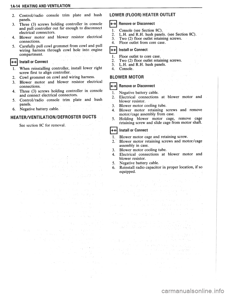
HEATER/VENTILATION/DEFROSTER DUCTS
See section 8C for removal.
LOWER (FLOOR) HEATER OUTLET
Remove or Disconnect
1. Console (see Section 8C).
2. L.H. and R.H. hush panels. (see Section 8C).
3. Two (2) floor outlet retaining screws.
4. Floor outlet from core case.
Install or Connect
1. Floor outlet to core case.
2. Two (2) floor outlet retaining screws.
3. L.H. and R.H. hush panels.
4. Console.
BLOWER MOTOR
Remove or Disconnect
1. Negative battery cable.
2. Electrical connections at blower motor and
blower resistor.
3. Blower motor cooling tube.
4. Blower motor retaining screws and remove
motor/cage assembly from case.
5. Holding blower motor cage, remove cage
retaining screw and slide cage from motor shaft.
Install or Connect
1. Blower motor cage and retaining screw.
2. Blower
motor retaining screws and
motor/cage
assembly in case.
3. Blower motor cooling tube.
4. Electrical connections at blower motor and
blower resistor.
5. Negative battery cable.
6. Reinstall radio capacitor in proper location, if so
equipped.
Page 44 of 1825
AIR CONDITIONING 1B-1
SECTION 1B
R COND
When performing air conditioning diagnosis on vehicles equipped with a catalytic converter, it will be necessary to
WARM the engine to a NORMAL operating temperature BEFORE attempting to idle the engine for periods greater
than five
(5) minutes. Once the engine attains normal idle, diagnosis and adjustments can be made.
CONTENTS
.................. General Description .................................. 1B-1 Accumulator Assembly Service .1B-19
.......................... C.C.O.T. A!C System ................................ 1B-1 On-Vehicle Sewice ..... 1B-20
....................................... System Components - Functional ................. 1B-2 Blower Motor .1B-20
..................................... System Components - Control ..................... 1B-3 Hi-Blower Relay 1B-20
...................................... Relays and Switches ................................... 1B-3 Blower Resistor 1B-20
Diagnosis ................................................. 1B-5 Controller, Blower Switch or Vacuum
................................................ Testing the Refrigerant System ...................... 1B-5 Valve .lB-20
Insufficient Cooling "Quick-Check Temperature Control Cable ....................... .1B-20
.................................... Procedure.. ............................................. 1B-5 Vacuum
Harness .lB-20
C.C.O.T. A/C System Diagnostic Control Wiring Harness ........................... .1B-20
..... ................................. Procedure.. ............................................. 1B-8 Heater
Core .. .lB-21
................................ Leak Testing ........................................... 1B-12 Lower Heater Outlet 1B-21
............................... Service Procedures ................................. .1B-12 Heater Module Case .lB-21
.......................... O-Ring Replacement ................................ .1B- 12 Pressure Cycling Switch .1B-21
....................................... Handling Refrigerant- 12 ............................ .1B- 13 Vacuum Tank .lB-21
Discharging, Adding Oil, Evacuating Liquid Line .......................................... .1B-23
and
Charging Procedures - AIC Accumulator ......................................... .1B-23
.................................... Systems .............................................. .1B-14 Evaporator Core .1B-24
In-Line Air Conditioning Evaporator Case .................................... .1B-24
.......................................... Filter
Installation.. .................................. .1B- 18 Compressor .lB-24
.............................................
................ Expansion Tube (Orifice) Service .1 B- 19 Condenser IB-24
GENERAL DESCRIPTION
All engines are equipped with a fixed displace- evaporator temperature. The pressure cycling switch
ment (R-4) air conditioning compressor. This
com- is the freeze protection device in the system and
pressor may cycle on and off under normal air
senses refrigerant pressure on the suction side of the
conditioning demand. system. This switch is located on a standard
Schrader- -
All air conditioning systems that use the fixed
displacement R-4 compressor are referred to as
C. C.O.T. (Cycling Clutch, Orifice Tube) type sys-
tems. This is the same system that has been used on
all General Motors vehicles in the past several years.
The C.C.O.T. NG System
The Cycling Clutch Orifice Tube (C.C.O.T.)
refrigeration system is designed to cycle a compressor
on and off to maintain desired cooling and to prevent
evaporator freeze. Passenger compartment comfort is
maintained by the temperature lever on the controller.
Control of the refrigeration cycle (on and off
operation of the compressor) is done with a switch
which senses low-side pressure as an indicator of type
valve low-side fitting. During air temperatures
over 10°C
(50°F), the equalized pressures within the
charged
A/C system will close the contacts of the
pressure switch. When an air conditioning mode
(max, norm, bi-level, defrost) is selected, electrical
energy is supplied to the compressor clutch coil. AS
the compressor reduces the evaporator pressure
to
approximately 175 kPa (25 psi), the pressure switch
will open, de-energizing the compressor clutch.
As
the system equalizes and the pressure reaches approxl-
mately 315 kPa (46 psi), the pressure switch contacts
close, re-energizing the clutch coil. This cycling
coy
tinues and maintains average evaporator discharge air
temperature at approximately 1°C (33°F). Because of
this cycling, some slight increases and decreases of
engine speedlpower may be noticed under certain con-
ditions. This is normal as the system is designed
to
cycle to maintain desired cooling, thus preventing
evaporator freeze-up.
Page 46 of 1825
AIR CONDITIONING 1 B-3
A low-side pressure Schrader valve service fit-
ting is located near the top of the accumulator. A
similar Schrader fitting may be provided for mounting
the pressure cycling switch. It is not necessary to dis-
charge the system to replace the switch. The accumu-
lator is serviced only as a replacement assembly.
Heater Core
The heater core heats the air before it enters the
car. Engine coolant is circulated through the core to
heat the outside air passing over the fins of the core.
The core is functional at all times (no water valve) and
may be used to temper conditioned air in
A/C mode,
as well as heat or vent mode.
SYSTEM COMPONENTS --- CON"FOL
Controller
The operation of the A/C system is controlled by
the switches and the lever on the control head. The
compressor clutch and blower are connected electri-
cally to the control head by a wiring harness. The
blower circuit is open in the off mode and air flow is
provided by the four blower speeds available in the
remaining modes. Cooled and dehumidified air is
available in the max, normal, bi-level and defrost
modes.
Temperature is controlled by the position of the
temperature lever on the control head. A cable con-
nects this lever to the temperature door which controls
air flow through the heater core. As the temperature
lever is moved through its range of travel, a sliding
clip on the cable at the temperature valve connection
should assume a position assuring that the temperature
door will seat in both extreme positions. Temperature
door position is independent of mode selection. The
temperature cable attaches to the right side of the air
conditioning module. The temperature door on some
models is controlled electrically, thereby eliminating
the need for the temperature cable.
The electric engine cooling fan on some cars is
not part of the
A/C system; however, the fan is
operational any time the
A/C control is in Max.,
Norm, or Bi-Level modes. Some models provide for
engine cooling fan operation when the controller is in
the defrost mode. This added feature is part of the
A/C
controller function and is aimed at preventing exces-
sive compressor head temperatures. It also allows the
A/C system to function more efficiently. On some
models during road speed (above
35 mph) conditions
when air flow through the condenser coil is adequate
for efficient cooling, the engine cooling fan will be
turned off. The operation of the cooling fan is con-
trolled by the ECM through the cooling fan relay.
Complete wiring diagrams and diagnosis for the
AIC Electrical System are in Section 8A. Section 8A
also contains additional diagnostic information
regarding air flows and vacuum logic.
Vacuum Lines
Vacuum lines are molded to a connector which
is attached to a vacuum control switch on the control
head assembly.
In case of leakage or hose collapse, it will not be
necessary to replace the entire harness assembly.
Replacement can be made by cutting the hose and
inserting a plastic connector. If an entire hose must be
replaced, cut all hoses off at the connector and then
attach hoses directly to the control head vacuum
switch. (NOTE: The Fiero uses an electric motor to
control mode selection. Therefore, it will not have a
vacuum harness.
)
Vacuum Tank
During heavy acceleration, the vacuum supply
from the carburetor drops. A check valve in the vac-
uum tank maintains vacuum so that, under load condi-
tions, vacuum will be available for continuous use.
REWVS AND SWITCHES
High-Pressure Compresssr Gut-OFF Switch
The high-side, high-pressure cut-off switch in
the rear head of the compressor is a protective device
intended to prevent excessive compressor head pres-
sures and reduce the chance of refrigerant escape
through a safety relief valve. Normally closed, this
switch will open the circuit at a high-side pressure of
approximately 2700
kPa (430 psi 9 20 psi) and
reclose the circuit at approximately 1379 kPa (200 psi
9 50 psi).
Lsw-Pressure Cut-On Switch
Compressor protection is provided on some cars
by a low-pressure cut-off switch which will open in
the event of a low-charge condition. This switch can
be located in the liquid line or in the rear head of the
compressor. This switch will also keep the compres-
sor from running during cold weather.
Pressure eyesing Switch
The refrigeration cycle (on and off operation of
the compressor) is controlled by a switch which
senses the low-side pressure as an indicator of evapo-
rator temperature. The pressure cycling switch is the
freeze protection device in the system and senses
refrigerant pressure on the suction side of the system.
This switch is located on a standard Schrader-type
valve low-side fitting. This switch also provides com-
pressor cut-off during cold weather.
Additional compressor protection results from
the operating characteristics of the low-side pressure
cycling system. If a massive discharge occurs or the
orifice tube becomes plugged, low-side pressures
could be insufficient to close the contacts of the pres-
sure switch. In the event of a low charge, insufficient
cooling accompanied by rapid compressor clutch
cycling will be noticed at high air temperatures.
Page 64 of 1825
AIR CONDITIONING 18-21
8. Disconnect blower motor
and blower resistor
electrical connection.
9. Remove hi-blower relay connector from evapo-
rator case.
10. Carefully pull
cowl grommet from cowl and pull
wiring
hmess into engine compartment.
Install or Connect
1. Reverse removal procedure to
reinstall. When
reinstalling controller, install lower right screw
first to align controller.
ACNENTILATIONIDEFROSVER DUCTS
See section 8C for removal.
HEATER CORE
Remove or Disconnect
1. Negative battery cable.
2. Drain cooling system.
3. Remove heater inlet and outlet hoses
from
heater core.
4. Remove right lower hush panel (see Section
8C).
5. Remove right
lower I.P. trim panel (see Section
8C) .
6. Remove lower right I.P. carrier to cowl screw.
7. Remove ECM attaching screws and move to the
side.
8. Remove four
(4) heater case cover screws.
Upper left screw may be reached with a long
318 ' socket extension through the I.P. openings
exposed by removal of the lower right I.P. trim
panel. Carefully lift the lower right corner of the
I.P. to align socket extension.
9. Remove heater case cover.
10. Remove core support plate
and baffle screws.
- -
11. Remove
heater core, support plate and baffle
from case.
Install or Conned
1. Reverse removal procedure to reinstall. Restore
all seals
and/or sealant disturbed during removal
procedure.
2. Refill cooling system and check for leaks.
LOWER (FLOOR) )-IEA"FEB$OU"fET
Remove or Disconnect
1. Console. (See Section 8C.)
2. L.H. and R.H. hush panels.
3. Two (2) floor outlet retaining screws.
4. Floor outlet from core case.
lnstall or Connect
1. Floor outlet to core case.
2. Two (2) floor outlet retaining screws.
3. L.H. and R.H. hush panels.
4. Console.
HEATER MODULE (CASE)
Remove or Disconnect
1. Disconnect negative battery cable.
2. Drain cooling system.
3. Remove hush panels and instrument panel car-
rier (see Section
8C).
4. Remove lower heater outlets.
5. Disconnect control cables and vacuum hoses at
module and controller.
6. Remove heater core.
7. Remove two (2) interior screws and one (I)
exterior nut holding case to cowl.
8. Remove evaporator core.
9. Remove screw holding case to cowl from engine
compartment side.
10. Remove case (module).
11. Transfer usable parts to new case (module).
lnstall or Conned
1. Reverse removal procedure to reinstall.
2. Refill coolant system.
3. Recharge
A/C system.
4. Inspect A/C and cooling system for leaks.
NC PRESSURE CYCLING SWITCH
Do not discharge A/C system. Pressure cycling
switch is mounted on
a Schrader-type valve.
Remove or Disconnect
1. Disconnect switch electrical connection.
2. Remove switch.
Install or Connect
1. Reverse removal procedure to reinstall. Tighten
switch to
4-5.5 N*m (35-49 in. lb.).
Ale CONTROL VACUUM TANK
Remove or Disconnect
1 . Disconnect vacuum hoses.
2. Remove vacuum
tank attaching screws, remove
tank.
lndall or Connect
1. Reverse removal procedure to
reinstall.
Page 67 of 1825
1B-24 AIR CONDPTIBNING
EVAPORATOR CORE
Remove QP Disconnect
1. Discharge A/C system.
2. Remove accumulator.
3. Remove two (2) screws and remove hi-blower
relay terminal.
4. Remove upper case screws.
5. Relocate wiring harness and remove dipstick.
6. Disconnect liquid line fitting.
7. Remove upper case and lift evaporator core out
of case (retain foam wedge).
Install or Connect
1. Reverse removal procedure to reinstall.
2. Recharge and test system for proper operation.
EVAPBRAWORCASE
Remove or Disconnect
1. Remove accumulator.
2. Remove blower motor.
3. Remove evaporator core.
Remove lower case to cowl screws (three driven from engine compartment, three driven from
interior).
Remove case from cowl.
Install or Connect
Reverse removal procedure to reinstall. Rein-
stall or replace gaskets, seal and sealant
removed during disassembly.
Recharge and test system for proper operation.
NG COMPRESSOR (TYPICAL)
Remove or Disconnect
1. Discharge A/C system.
2. Remove fitting block (coupled hose assembly)
bolt at rear of compressor.
3. Remove mounting bracket bolt(s) .
4. Remove drive belt (route lower loop behind har-
monic balancer to gain additional slack if
required).
5. Remove compressor. If complete compressor is
to be replaced, transfer usable switches, etc. to
new compressor.
Install or Connect
1. Reverse removal
procedure to reinstall. Use
new O-rings lubricated with
525 viscosity
refrigerant oil. Refer to Section
6B for drive belt
tension.
2. Evacuate and recharge system.
CONDENSER
a Remove or Disconnect
1. Discharge A/C system.
2. Disconnect coupled hose and liquid line fittings.
3, Remove screws retaining top radiator shield.
4. Remove top condenser retaining screws.
5. Carefully move (tilt) radiator rearward and lift
condenser out of radiator support.
6. Transfer brackets and mounts to new condenser
if replacement is necessary.
Install or Connect
1. Reverse removal procedure to reinstall. Use
new O-rings lubricated with
525 viscosity
refrigerant oil.
2. Recharge and test system for proper operation.
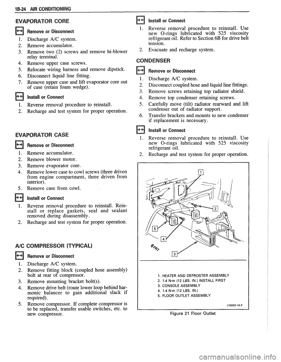
1. HEATER AND DEFROSTER ASSEMBLY
2. 1.4
N.m (12 LBS. IN.) INSTALL FIRST
3. CONSOLE ASSEMBLY
4.
1.4 Narn (12 LBS. IN.)
5. FLOOR OUTLET ASSEMBLY
Figure 21 Floor Outlet