1988 PONTIAC FIERO wiring
[x] Cancel search: wiringPage 478 of 1825
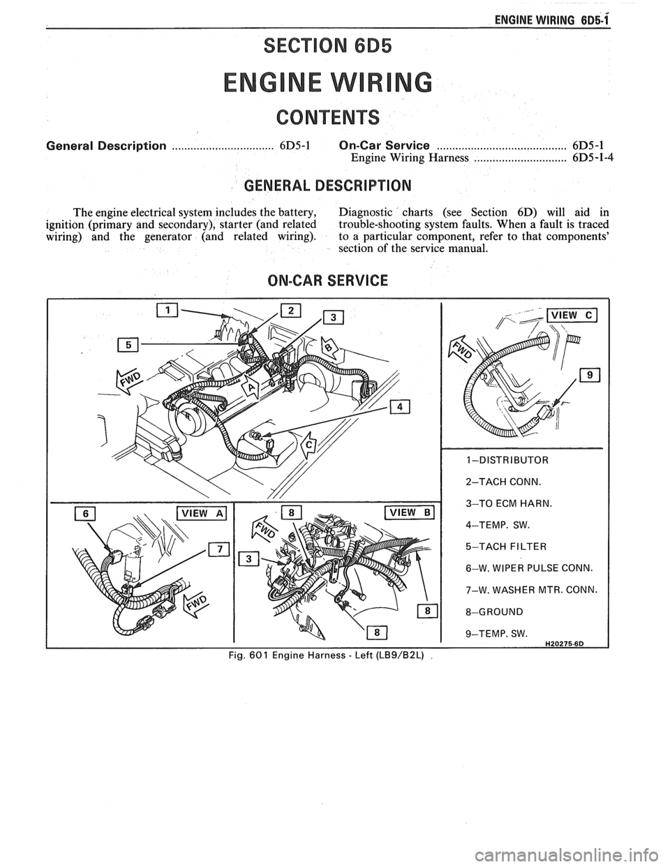
ENGINE WIRING 6~5-1x
SECTION 6B5
General Description ................................. 6D5-1 On-Car Service ........................................ 6D5 -1
Engine Wiring Harness ..................... .. .. 6D5 -1-4
GENERAL DESCRIPTION
The engine electrical system includes the battery, Diagnostic charts (see Section 6D) will aid in
ignition (primary and secondary), starter (and related trouble-shooting system faults. When
a fault is traced
wiring) and the generator (and related wiring). to a particular component, refer to that components'
section of the service manual.
ON-CAR SERVICE
Page 479 of 1825
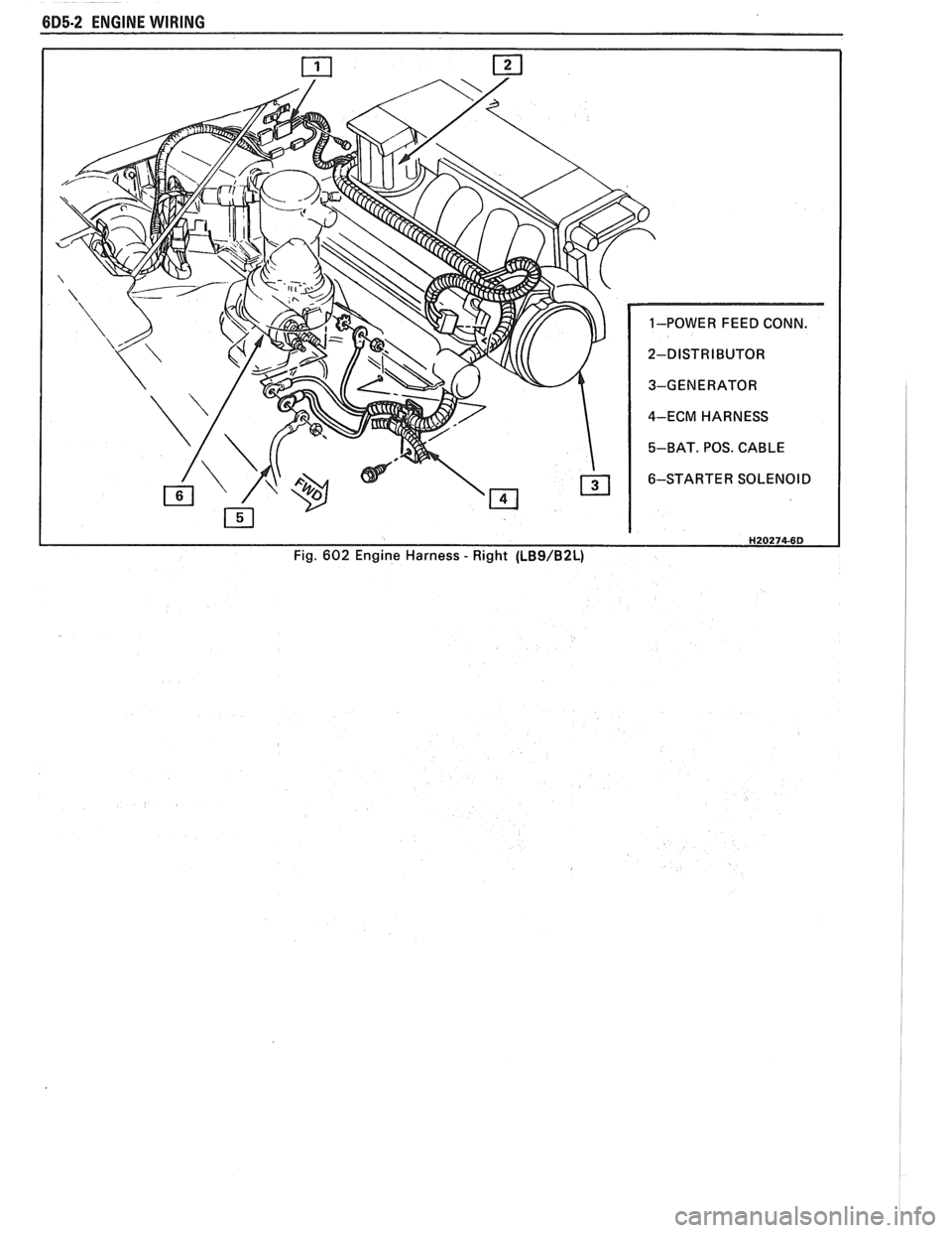
685-2 ENGINE WIRING
H20274-6D Fig. 602 Engine Harness - Right (LBS/B2L)
Page 480 of 1825
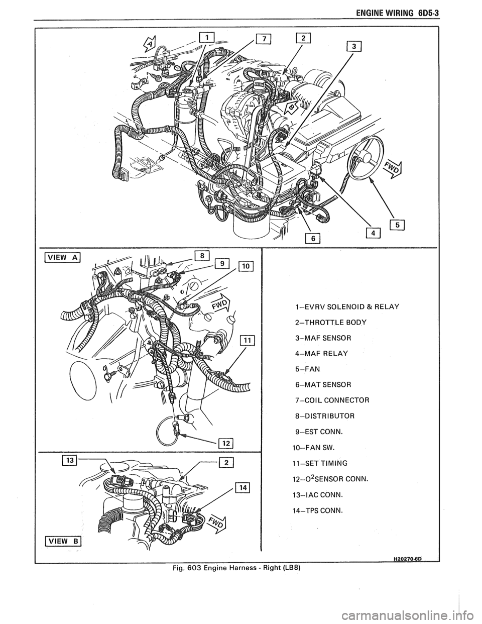
ENGINE WIRING 605.3
1-EVRV SOLENOID & RELAY
2-THROTTLE BODY
3-MAF SENSOR
4-MAF RELAY
6-MAT SENSOR
7-COIL CONNECTOR
8-DISTRIBUTOR 9-EST CONN.
10-FAN SW.
11-SET
TIMING
I~-O~SENSOR CONN.
13-IAC CONN.
14-TPS CONN.
Fig. 603 Engine Harness
- Right (LB8)
Page 481 of 1825
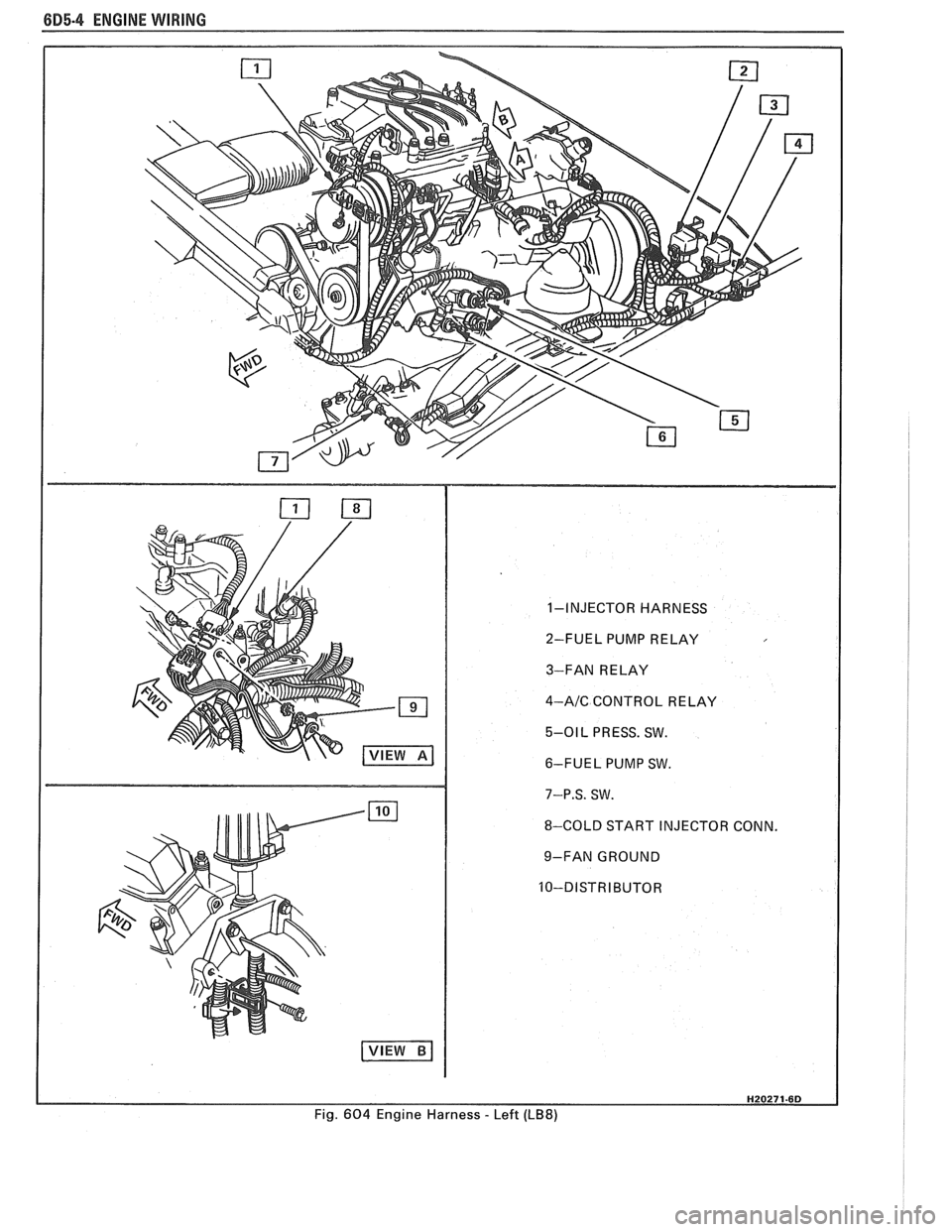
6D5-4 ENGINE WIRING
1-INJECTOR HARNESS
2-FUEL PUMP RELAY
3-FAN RELAY
4-AIC CONTROL RELAY
5-01 L PRESS. SW.
6-FUEL PUMP SW.
7-P.S. SW.
8-COLD START INJECTOR CONN.
9-FAN GROUND
Fig.
604 Engine Harness - Left (LB8)
Page 482 of 1825
ENGINE ELECTRICAL 6B.l
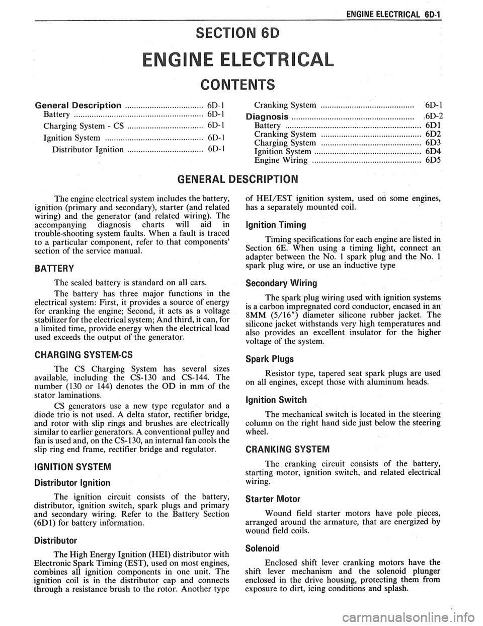
SECTION 6D
NE ELECTR
General Description ................................... 6D- 1 Cranking System ..................................... 6D- 1
Battery .................... ... .............................. 6D- 1 ....................................................... Diagnosis ,6D-2
.................................. Charging System - CS 6D- 1 Battery ................... .. ..................................... 6D1
......................................... Ignition System ............................................ 6D- 1 Cranking System 6D2
Charging System .......................... .. ............... 6D3 .................................. Distributor Ignition 6D- 1 Ignition Svstem .......................................... 6D4 - Engine Wiring ................................................ 6D5
GENERAL DESCRIPTION
The engine electrical system includes the battery,
ignition (primary and secondary), starter (and related
wiring) and the generator (and related wiring). The
accompanying diagnosis charts will aid in
trouble-shooting system faults. When a fault is traced
to a particular component, refer to that components'
section of the service manual.
BATTERY
The sealed battery is standard on all cars.
The battery has three major functions in the
electrical system: First, it provides a source of energy
for
cranking the engine; Second, it acts as a voltage
stabilizer for the electrical system; And third, it can, for
a limited time, provide energy when the electrical load
used exceeds the output of the generator.
CHARGING SYSTEM-CS
The CS Charging System has several sizes
available, including the CS-130 and CS-144. The
number (130 or 144) denotes the
OD in mm of the
stator laminations.
CS generators use a new type regulator and a
diode trio is not used. A delta stator, rectifier bridge,
and rotor with slip rings and brushes are electrically
similar to earlier generators. A conventional pulley and
fan is used and, on the CS-130, an internal fan cools the
slip ring end frame, rectifier bridge and regulator.
IGNITION SYSTEM
Distributor Ignition
The ignition circuit consists of the battery,
distributor, ignition switch, spark plugs and primary
and secondary wiring. Refer to the Battery Section
(6D 1) for battery information.
Distri but~r
The High Energy Ignition (HEI) distributor with
Electronic Spark Timing (EST), used on most engines,
combines all ignition components in one unit. The
ignition coil is in the distributor cap and connects
through a resistance brush to the rotor. Another type of
HEVEST ignition system,
used on some engines,
has a separately mounted coil.
Ignition Timing
Timing specifications for each engine are listed in
Section 6E. When using a timing light, connect an
adapter between the No. 1 spark plug and the No. 1
spark plug wire, or use an inductive type
Secondary Wiring
The spark plug wiring used with ignition systems
is a carbon impregnated cord conductor, encased in an
8MM (5/16") diameter silicone rubber jacket. The
silicone jacket withstands very high temperatures and
also provides an excellent insulator for the higher
voltage of the system.
Spark Plugs
Resistor type, tapered seat spark plugs are used
on all engines, except those with aluminum heads.
lgnition Switch
The mechanical switch is located in the steering
column on the right hand side just below the steering
wheel.
CRANKING SYSTEM
The cranking circuit consists of the battery,
starting motor, ignition switch, and related electrical
wiring.
Starter Motor
Wound field starter motors have pole pieces,
arranged around the armature, that are energized by
wound field coils.
Solenoid
Enclosed shift lever cranking motors have the
shift lever mechanism and the solenoid plunger
enclosed in the drive housing, protecting them from
exposure to dirt, icing conditions and splash.
Page 483 of 1825
8B-2 ENGINE ELECTRICAL
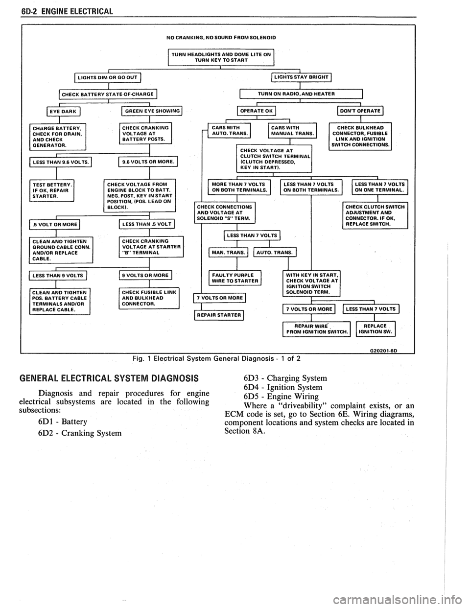
NO CRANKING, NO SOUND FROM SOLENOID
I TURN HEADLIGHTS AND DME LITE ON
TURN KEY TO START I
TEST BETTERY.
IF OK. REPAIR
.5 VOLT OR MORE a
OSITION, (POS. LEAD 0
GROUND CABLE CONN. ANDlOR REPLACE
CABLE.
CLEAN AND TIGHTEN
POS. BATTERY CABLE
TERMINALS
ANDlOR REPLACE CABLE. CONNECTOR.
FUSIBLE
CHECK CONNECTIONS
AND VOLTAGE AT
SOLENOID
"S' TERM.
LESS THAN
7 VOLTS b
FAULTY PURPLE WITH KEY IN START,
WIRE TO STARTER CHECK
VOLTAGE AT
G20201-6D
Fig. 1 Electrical System General Diagnosis - 1 of 2
GENERAL ELECTRICAL SYSTEM DIAGNOSIS 6D3 - Charging System
6D4
- ~~nitcon-§~stem Diagnosis and repair procedures for engine
6D5 - Engine Wiring
electrical subsystems are located in the following
subsections: Where a
"driveability" complaint
exists, or an
ECM code is set, go to Section
6E. Wiring diagrams,
6D
1 - Battery component locations and system checks are located in
6D2
- Cranking System Section 8A.
Page 486 of 1825
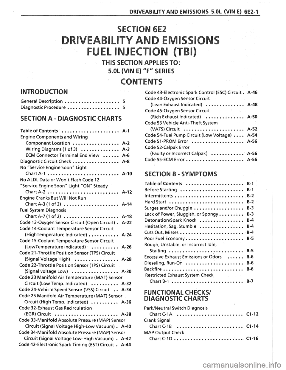
SECTION 6E2
TY AND EM
THIS SECTION APPLIES TO:
5.OL (VIN E) ""FYSERIES
CONTENTS
General Description .................... 5
Diagnostic Procedure ................... 5
SECTION A . DIAGNOSIIC CHARTS
Table of Contents ..................... A-1
Engine Components and Wiring
Component Location
................. A-2
Wiring Diagrams (1 of 3) .............. A-3
ECM Connector Terminal End View ...... A-6
Diagnostic Circuit Check ................. A-8
No "Service Eng~ne Soon" Light
Chart
A-1 .......................... A-10
No ALDL Data or Won't Flash Code 12
"Service Engine Soon" Light "ON" Steady
Chart A-2
.......................... A-1 2
Engine Cranks But Will Not Run
ChartA-3
(1 of 2) .................... A-14
Fuel System Diagnosis
ChartA-7(1 of 2) .................... A-18
Code 13-Oxygen Sensor Circuit (Open Circuit) . A-22
Code 14-Coolant Temperature Sensor Circuit
(HighTemperature Indicated) ........... A-24
Code 15-Coolant Temperature Sensor Circuit
(LowTemperature Indicated) .......... A-26
Code 21-Throttle Position Sensor (TPS) C~rcuit
(Signal Voltage High) ................ A-28
Code 22-Throttle Position Sensor (TPS) C~rcuit
(Signal voltage Low) ................. A-30
Code 23 Manifold Air Temperature (MAT) Sensor
. Circuit (Low Temp Indicated) .......... A-32
Code 43-Electronic Spark Control (ESC) Circuit . A46
Code 44-Oxygen Sensor Circu~t
(Lean Exhaust Indicated) .............. A-48
Code 45-Oxygen Sensor Circu~t
(Rich Exhaust Indicated) .............. A-50
Code 53 Vehicle Anti-Theft System
(VATS)
Circu~t ...................... A-52
Code 54-Fuel Pump Circuit (Low Voltage) .... A-54
Code 51 -PROM Error ................... A-56
Code 52-Calpak Error
(Faulty or Incorrect
Calpak) ............ A-56
Code 55-ECM Error ..................... A-56
SECTION B . SYMPTOMS
Table of Contents ..................... B-1
Before Starting ....................... B-1
Intermittents ......................... B-2
Hard Start ........................... 8-2
.................. Surges and/or Chuggle B-3
Lack of Power. Sluggish. or Spongy ......... 8-3
DetonationISpark Knock ................ 8-4
................ Hesitation. Sag. Stumble B-4
Cuts Out. Misses ....................... B-4
Poor Fuel Economy ..................... B-5
Rough. Unstable. or Incorrect Idle.
. Stalling ....................... ... B-5
Excessive Exhaust Emtss~ons or Odors ...... 8-6
Dieseling. Run-on ..................... 8-6
Backfire ............................. B-6
Restricted Exhaust System Check
Chart
B-1 .......................... 8-7
Code 24-Vehicle Speed Sensor (VSS) Circuit . . A-34
Code 25 Manifold Air Temperature (MAT) Sensor FUNCTIONAL CHECKS/
Circuit (High Temp . Indicated) .......... A-36 DIAGNOSqIC CHARTS
Code 32-Exhaust Gas Recirculat~on ParkINeutral Switch Diagnosis
........................ (EGR) Circuit ....................... A-38 Chart C- 1 A C1-12
Code 33-Manifold Absolute Pressure (MAP) Sensor Crank Signal
Circuit (Signal Voltage High-Low Vacuum)
. A-40 Chart C-1 B ........................ C1-14
Code %&Manifold Absolute Pressure (MAP) Sensor MAP
Output Check
......................... Circuit (Signal Voltage Low-High Vacuum) . A-42 ChartC-ID C1-16
Code 42-Electronic Spark Timing (EST) Circuit . A-44
Page 492 of 1825
DRIVEABILITY AND EMISSIONS S.OL (VIN E) 6EZ-A-1
5.OL ENGINE
DIAGNOS"FC CIRCUIT CHECK Cold Oxygen Sensor
The "Diagnostic Circuit Check" verifies the On some engines. the oxygen sensor will cool off
system is functioning correctly
. Some special after only a short period of operation at idle . This will
considerations to keep in mind while making the
put the system into "Open Loop"
. To restore "Closed
"Diagnostic Circuit Check" are:
Loop" operation. run the engine at part throttle
several minutes and accelerate from idle to part
Blocking Drive Wheels throttle a few times .
The vehicle drive wheels should always be blocked BASIC PROCEDURE
while checking the system .
If you have not reviewed the basic information on
how to use the diagnostic procedures. go to the
introduction of this section
.
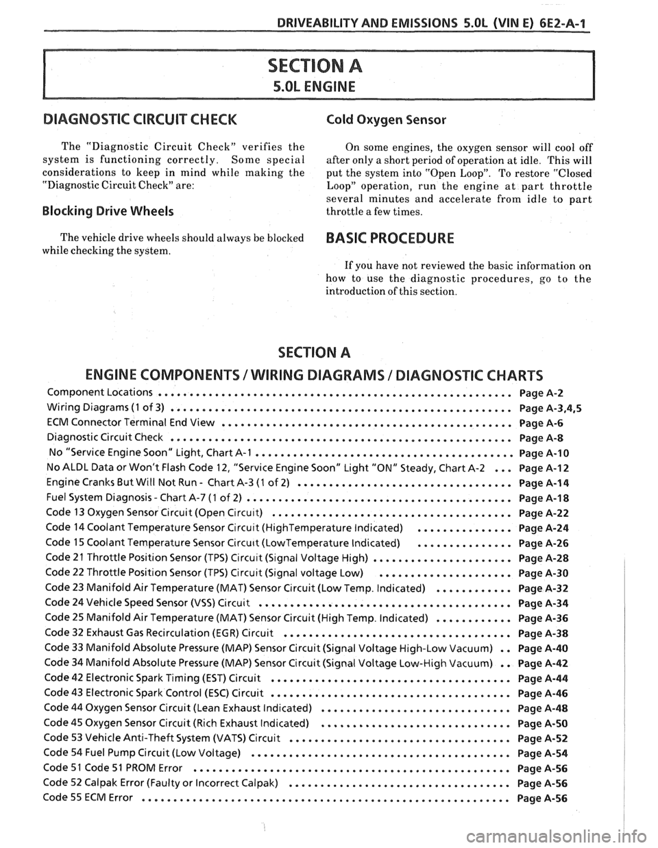
SECTION A
ENGINE COMPONENTS
/ WlRlNG DIAGRAMS 1 DIAGNOSTIC CHARTS
Component Locations ........................................................ Page A-2
Wiring Diagrams (1 of 3) ...................................................... Page A.3.4.5
ECM Connector Terminal End View .............................................. Page A-6
Diagnostic Circuit Check ...................................................... Page A-8
No "Service Engine Soon" Light. Chart A-1 ......................................... Page 14-10
No ALDL Data or Won't Flash Code 12. "Service Engine Soon" Light "ON" Steady. Chart A-2 ... Page A-I 2
Engine Cranks But Will Not Run . Chart A-3 (1 of 2) .................................. Page A-1 4
. Fuel System Diagnosis Chart A-7 (1 of 2) .......................................... Page A-1 8
Code 13 Oxygen Sensor Circuit (Open C~rcu~t) ...................................... Page A-22
Code 14 Coolant Temperature Sensor Circu~t (HighTemperature Indicated) ............... Page A-24
Code 15 Coolant Temperature Sensor Circu~t (LowTemperature Indicated) ............... Page A-26
Code 21 Throttle Position Sensor (TPS) Circu~t (S~gnal Voltage High) ...................... Page A-28
Code 22 Throttle Position Sensor (TPS) Circuit (Signal voltage Low) ..................... Page A-30
Code 23 Manifold Air Temperature (MAT) Sensor Circuit (Low Temp . Indicated) ............ Page A-32
Code 24 Vehicle Speed Sensor (VSS) Circuit ........................................ Page A-34
Code 25 Manifold Air Temperature (MAT) Sensor Circuit (High Temp . Indicated) ............ Page A-36
Code 32 Exhaust Gas Recirculation (EGR) Circuit .................................... Page A-38
Code 33 Manifold Absolute Pressure (MAP) Sensor Circuit (Signal Voltage High-Low Vacuum) . . Page A-40
Code 34 Manifold Absolute Pressure (MAP) Sensor Circuit (Signal Voltage Low-High Vacuum) . . Page A-42
Code 42 Electronic Spark Timing (EST) Circuit ...................................... Page A-44
Code 43 Electronic Spark Control (ESC) Circuit ...................................... Page A-46
Code 44 Oxygen Sensor Circuit (Lean Exhaust Indicated) .............................. Page A-48
Code 45 Oxygen Sensor Circuit (Rich Exhaust Indicated) .............................. Page A-50
Code 53 Vehicle Anti-Theft System (VATS) Circuit ................................... Page A-52
Code 54 Fuel Pump Circuit (Low Voltage) ......................................... Page A-54
Code 51 Code 51 PROM Error .................................................. Page A-56
Code 52 Calpak Error (Faulty or Incorrect Calpak) ................................... Page A-56
.......................................................... Code55ECMError PageA-56