1988 PONTIAC FIERO wiring
[x] Cancel search: wiringPage 557 of 1825
6EZ-C1-2 5.OL (VIN E) DRIVEABILITY AND EMISSIONS
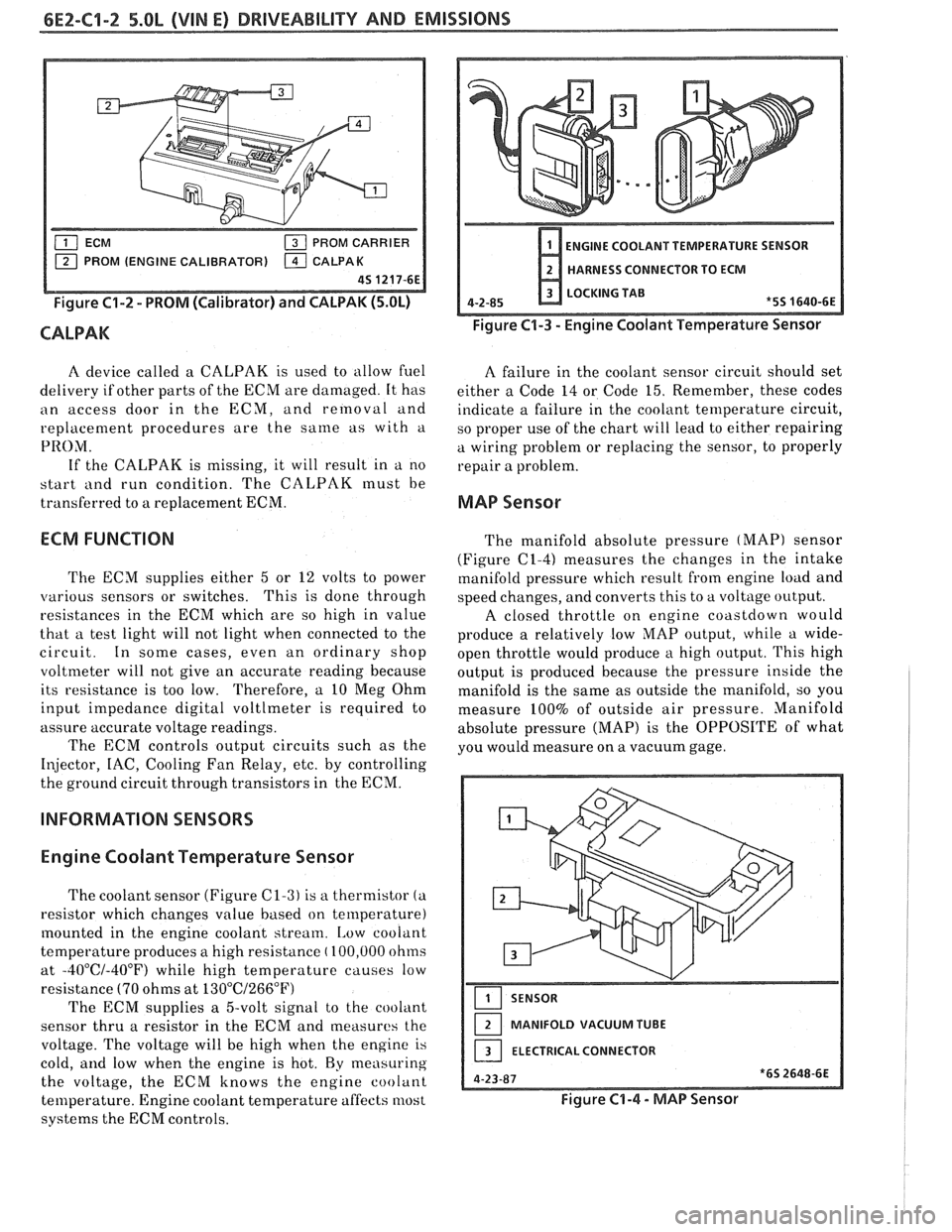
PROM CARRIER
PROM (ENGINE CALIBRATOR)
Figure C1-2 - PROM (Calibrator) and CALPAK (5.OL)
CALPAK
ENGINE COOLANT TEMPERATURE SENSOR
HARNESS CONNECTOR TO ECM
LOCKING TAB
4-2-85
*5S 1640-6E
Figure C1-3 - Engine Coolant Temperature Sensor
A device called a CALPAK is used to allow fuel
A failure in the coolant sensor circuit should set
delivery if other parts of the ECM are damaged. It has
either a Code 14 or Code 15. Remember, these codes
an access door in the ECM, and removal and
indicate a failure in the coolant temperature circuit,
replacement procedures are the
same as with a
so proper use of the chart will lead to either repairing
PRO;\/I. a wiring problem or replacing the sensor, to properly
If the CALPAK is missing, it will result in a no
repair a problem.
start
i111d run condition. The CALPAK must be
transferred to a replacement ECM.
MAP Sensor
ECM FUNCTION
The ECM supplies either 5 or 12 volts to power
various sensors or switches. This
is done through
resistances in the ECM which are so high in value
that a test light will not light when connected to the
circuit. In some cases, even an ordinary shop
voltmeter will not give an accurate reading because
its resistance is too low. Therefore, a 10 Meg Ohm
input impedance digital voltlmeter is required to
assure accurate voltage readings.
The ECM controls output circuits such as the
Injector, IAC, Cooling Fan Relay, etc. by controlling
the ground circuit through transistors in the ECM.
INFORMATION SENSORS
Engine Coolant Temperature Sensor
The coolant sensor (Figure C1-3) is a thermistor (a
resistor which changes value based on temperature)
mounted in the engine coolant stream.
[,ow coolant
temperature produces a high resistance
( 100,000 ohms
at
-40°C/-40°F) while high temperature causes low
resistance
(70 ohms at 13O0C/266"F)
The ECM supplies a 5-volt signal to the cooliint
sensor thru a resistor in the ECM and measures the
voltage. The voltage will be high when the engine is
cold,
and low when the engine is hot. By measuring
the voltage, the ECM knows the engine coolant
temperature. Engine coolant temperature affects most
systems the ECM controls. The
manifold absolute pressure
(MAP) sensor
(Figure
(21-4) measures the changes in the intake
manifold pressure which result from engine load and
speed changes, and converts this to a voltage output.
A closed throttle on engine coastdown would
produce a relatively low
MAP output, while a wide-
open throttle would produce a high output. This high
output is produced because the pressure inside the
manifold is the same as outside the manifold, so you
measure 100% of outside air pressure. Manifold
absolute pressure (MAP) is the OPPOSITE of what
you would measure on a vacuum gage.
SENSOR
MANIFOLD VACUUM TUBE
ELECTRICAL CONNECTOR
Figure C1-4 - MAP Sensor
Page 606 of 1825
DRIVEABILITY AND EMISSIONS 5.OL (VIN E) 6E2-C5-1
ELECmONIC SPARK CONTROL (ESC) SYSTEM
CONTENTS
GENERAL DESCRIPTION ................ C5-1 ON-CAR SERVICE ..................... C5-1
PURPOSE
......................... C5-1 ESC KNOCK SENSOR ................ C5-1
OPERATION
....................... C5-1 ESC MODULE ...........e..e.e..... C5-1
DIAGNOSIS
......................... C5-1 PARTS INFORMATION ................. C5-2
RESULTS OF INCORRECT ESC OPERATION
. C5-1
GENERAL DESCRIPTION
PURPOSE
To control spark knock, an electronic spark control
(ESC) system has been added. This system is designed
to retard spark timing up to
20°, to reduce spark knock
in the engine. This allows the engine to use maximum
spark advance to
improve driveability and fuel
economy. Varying octane levels in today's gasoline can
cause detonation in high performance engines.
Detonation is called spark knock. Loss
of the ESC signal to the ECM would cause the
ECM to constantly retard EST. This could result in
sluggish performance and cause a Code
43 to set.
A "Scan" tool will read knock signal in
AID
counts. When detonation is detected, knock signal
counts will increment,
as long as knock is present.
"Scan" tools will indicate knock being present either
by showing
AID counts, or displaying Yes (knock
present), or No (knock not present). If Code
43 is
present, use that chart to diagnose system. If no code
is present and ESC system is suspected, use CHART
C-5.
ON-CAR SERVICE
OPERATION
ESC KNOCK SENSOR
'I'he ESC system has two major components:
e ESC Module
@ ESC Knock Sensor
The sensor is mounted in the engine block near
the cylinders, or in the intake manifold at the rear of
the engine. When the ESC knock sensor detects
abnormal vibration (spark knocking) in the engine, it
produced
a voltage that is received by the ESC
module. As long as the ESC module sees no voltage
from the knock sensor (knock not present), it sends a
signal voltage
(8 to 10 volts) to the ECM and the ECM
provides normal spark advance.
When the module
d'etects voltage from the knock
sensor (knock present), it turns "OFF" the signal to
the ECM and the voltage at terminal
B7 goes to 0
volts: The ECM then retards EST to reduce spark
knock.
DIAGNOSIS
See Figure C5-1.
Remove or Disconnect
1. Negative battery cable.
2. ESC wiring harness connector from ESC sensor.
3. ESC sensor from engine block.
Install or Connect
I. ESC sensor into engine block. Apply thread
sealer, such as soft tape, to the ESC sensor
threads.
2. ESC wiring harness connector to the ESC sensor.
3. Negative battery cable.
ESC MODULE
RESULTS OF INCORRECT ESC OPERATION
Refer to Figure C5- 1
Loss of the ESC knock sensor signal or loss of
ground at ESC module would cause the signal to the a Remove or Disconnect
ECM to remain hiph. This condition would cause the 1. ESC module connector. L. ECM to control EST, as if no spark knocking were 2. Attachingscrews.
happening. No retard would occur, and spark 3. p;SCmodule.
knocking could become severe under heavy engine
load conditions.
Page 617 of 1825
6E2-C6-6 DRIVEABILITY AND EMISSIONS - 5.OL (VIN E)
A.I.W. CONVERTER SOL.
CONNECTORS
429 BLWPNK
CONNECTOR CONNECTOR
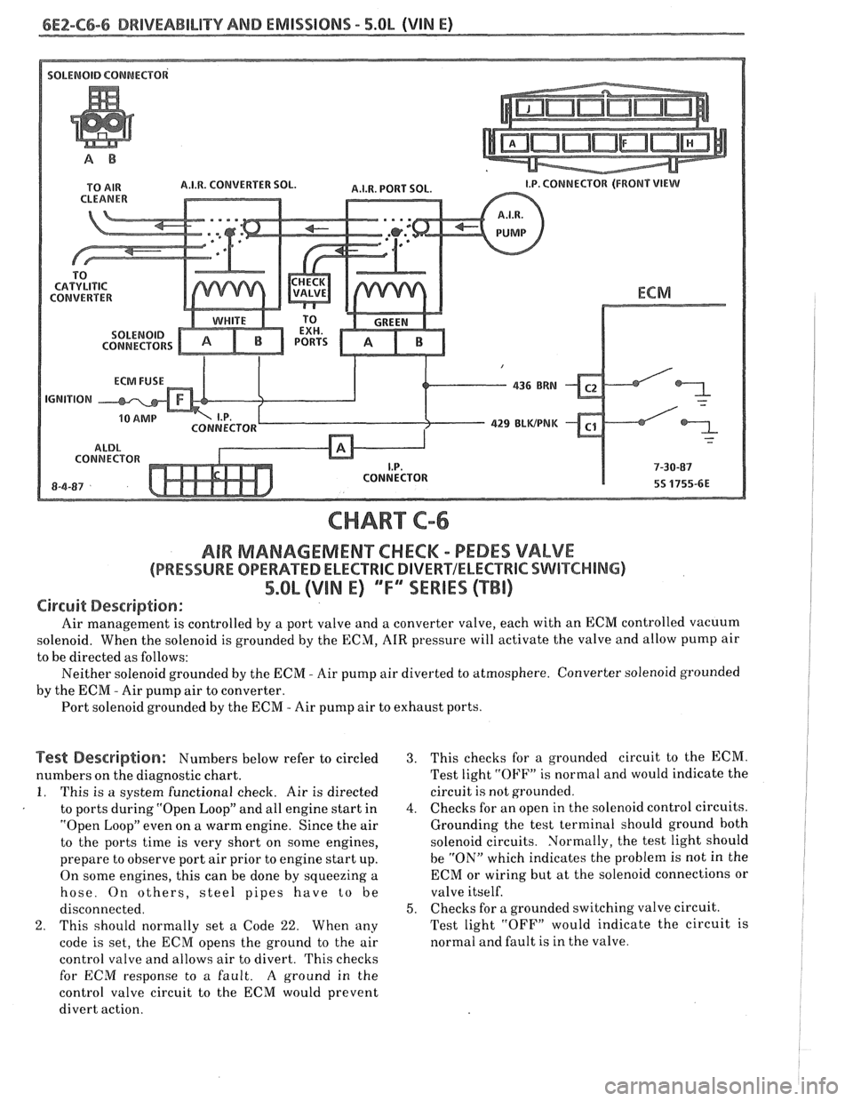
CHART C-6
AIR MAMAGEMENKHECM - PEDES VALVE
(PRESSURE OPERATED ELECTRlC DIVERVELECTRIC SWITCHING)
5.Qb (VIN E) ""FYSERIES (TBI)
Circuit Description:
Air management is controlled by a port valve and a converter valve, each with an ECM controlled vacuum
solenoid. When the solenoid is grounded by the ECM,
AIR pressure will activate the valve and allow pump air
to be directed as follows:
Neither solenoid grounded by the
ECM - Air pump air diverted to atmosphere. Converter solenoid grounded
by the
ECIM - Air pump air to converter.
Port solenoid grounded by the ECM
- Air pump air to exhaust ports.
Test Description: Numbers below refer to circled
numbers on the diagnostic chart.
I. This is a system functional check. Air is directed
to ports during "Open Loop" and all engine start in
"Open Loop" even on a warm engine. Since the air
to the ports time is very short on some engines,
prepare to observe port air prior to engine start up.
On some engines, this can be done by squeezing a
hose. On others, steel pipes have
to be
disconnected.
2. This should normally set a Code 22. When any
code is set, the
ECM opens the ground to the air
control valve and allows air to divert. This checks
for
ECM response to a fault. A ground in the
control valve circuit to the ECM would prevent
divert action.
3. This checks for a grounded circuit to the ECM.
Test light
"OFF" is normal and would indicate the
circuit
is not grounded.
4. Checks for an open in the solenoid control circuits.
Grounding the test terminal should ground both
solenoid circuits. Normally, the test light should
be "ON" which indicates the problem is not in the
ECM or wiring but at the solenoid connections or
valve itself.
5. Checks for a grounded switching valve circuit.
Test light "OFF" would indicate the circuit is
normal and fault is in the valve.
Page 631 of 1825
6E2-C8-6 DRIVEABILITY AND EMISSIONS - 5.OL (VIN E)
I.P. HARNESS CONNECTOR 15 WAY (FRONT VIEW)
ECM
VEHICLE SPEED SIGNAL
SPEED INPUT
4TH GEAR SIGNAL
422 TANIBLK
ALDL CONNECTOR
* 85 4435-66 6-8-87
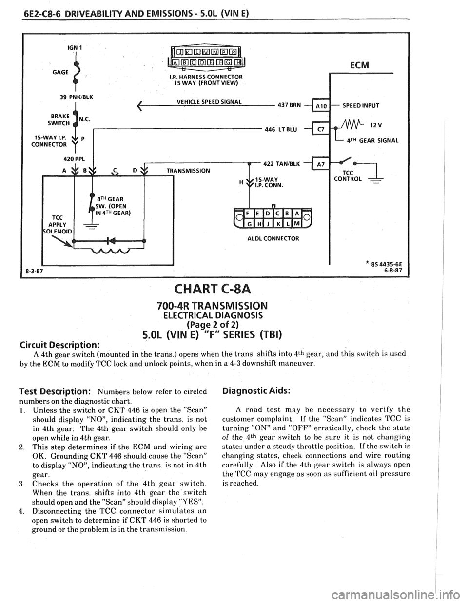
CHART C-8A
700-4R TRANSMISSION
ELECTRICAL DIAGNOSIS
(Page 2 of 2)
5.0L (VIN E) "F" "SERIES (TBI)
Circuit Description:
A 4th gear switch (mounted in the trans.) opens when the trans. shifts into 4th gear, and this switch is used
by the ECM to modify TCC lock and unlock points, when in a 4-3 downshift maneuver.
Test Description: Numbers below refer to circled
numbers on the diagnostic chart.
1. Unless the switch or CKT 446 is open the "Scan"
should display "NO", indicating the trans. is not
in 4th gear.
The 4th gear switch should only he
open whiie in 4th gear.
2. This step determines if the ECM and wiring are
OK. Grounding CKT 446 should cause the "Scan"
to display "NO", indicating the trans. is not in 4th
gear.
3. Checks the operation of the 4th gear switch.
When the trans. shifts into 4th
geir the switch
should open and the "Scan" should display
"YES".
4. Disconnecting the TCC connector simulates an
open switch to determine if CKT
446 is shorted to
ground or the problem is in the transmission.
Diagnostic Aids:
A road test may be necessary to verify the
customer complaint. If the "Scan" indicates TCC is
turning
"ON" and "OFF" erratically, check the state
of the 4th gear switch to he sure it is not changing
states under a steady throttle position.
If the switch is
changing states, check connections and wire routing
carefully. Also if the 4th gear switch is always open
the
TCC may engage as soon as sufficient oil pressure
is reached.
Page 633 of 1825
6E2-C8-8 DRIVEABILITY AND EMISSIONS - 5.OL (VIN E)
I.P. HARNESS CONNECTOR
INTRUMENT 15 WAY. (FRONT VIEW)
CHART C-8B
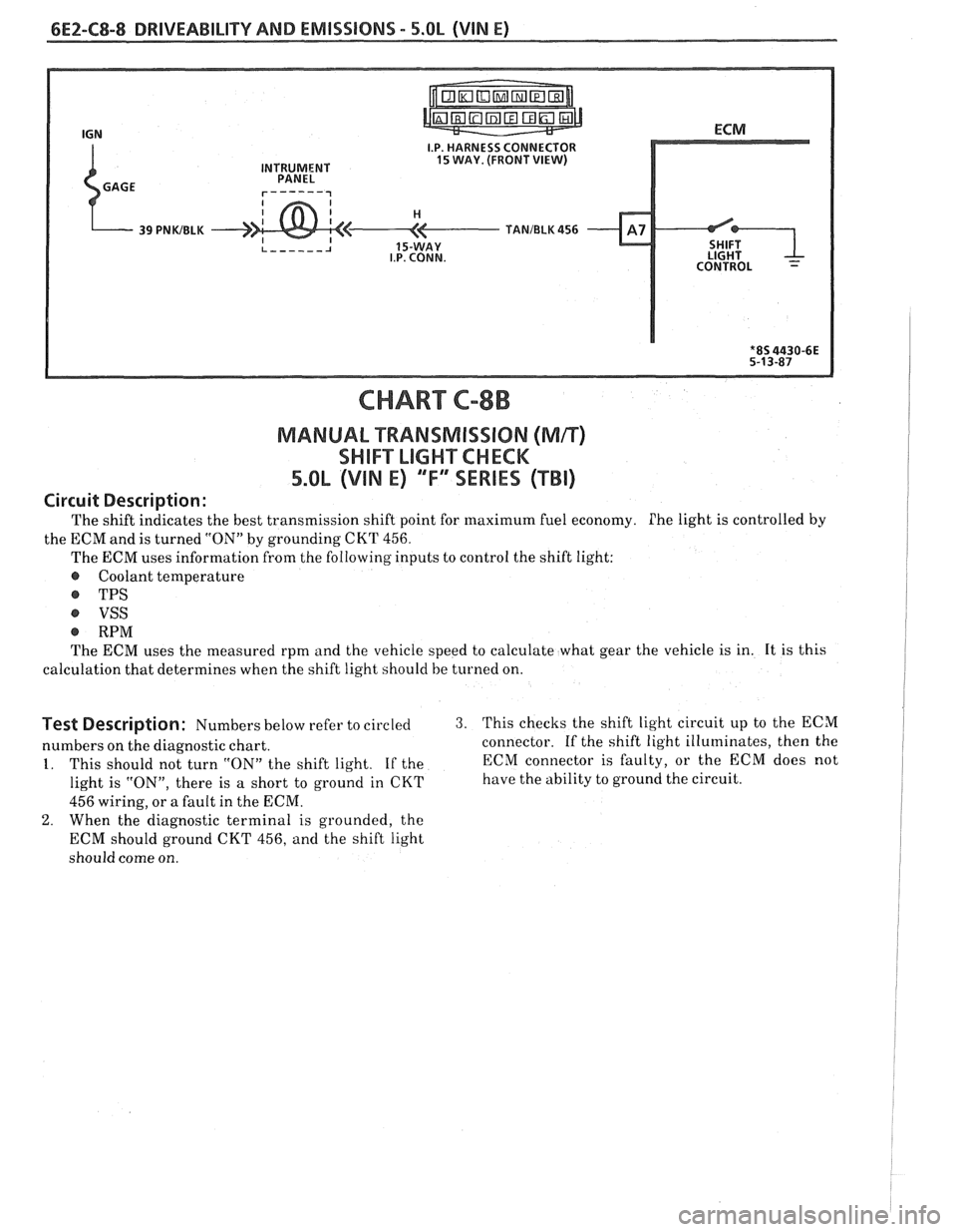
MANUAL "TRANSMISSION (Mn)
SWIFT LIGHXCHCK
5.OL (VIN E) "F" "SERIES ("Ti)
Circuit Description:
The shift indicates the best transmission shift point for maximum fuel economy. Phe light is controlled by
the ECM and is turned "ON" by grounding
CKT 456.
The ECM uses information from the following inputs to control the shift light:
@ Coolant temperature
@ TPS
VSS
@ RPM
The ECM uses the measured rpm and the vehicle speed to calculate what gear the vehicle is in. It is this
calculation that determines when the shift light should be
turned on.
Test Description: Numbers below refer to circled 3. This checks the shift light circuit up to the ECM
numbers on the diagnostic chart. connector.
If the shift light illuminates, then the
1. This should not turn "ON" the shift light. If the ECM
connector is faulty, or the ECM does not
light is "ON", there is
a short to ground in CKT have the ability to ground the circuit.
456 wiring, or a fault in the ECM.
2. When the diagnostic terminal is grounded, the
ECM should ground CKT 456, and the shift light
should come on.
Page 643 of 1825
INDEX
SECTION PACE
....................... Detonation... B-4
.................. Diagnostic Procedure 2-5
................ Diagnostic Circuit Check A-8
..................... Dieseling. Run On B-6
Distributor Reference Signal
................. General Description C1-4
......................... Diagnosis C1-5
E
.................... ECM Terminals ... A-6
.................. ECM Wiring Diagram A3-A6
..................... EGR Control Valve C7-1
................. Valve Identification C7-2
................... Diagnosis. Service C7-2
EGR Control Solenoid
.................. C7-3
Parts Information
................... C7-3
......................... EGR Check C7-4
Electronic Control Module
................. General Description C1-I
......................... Diagnosis C1-5
............................ Service C1-6
..................... Function Check C1-6
Electronic Spark Control (ESC) System
................. General Description C5-1
................... Diagnosis. Service C5-I
Engine Coolant Temperature Sensor
................. General Description C1-2
......................... Diagnosis C1-5
Engine Cranks But Won't Run
............ A-14
........................ Engine Knock C5-4
.......................... ESC Module C5-1
.......................... ESC Sensor C5-1
..................... ESC System Check C5-4
ESTIlgnition System ................... C4-1
Evaporative Emission
Conirol System
General Description
................. C3-1
.......................... Diagnosis C3-2
Exhaust Emissions Excessive (Odors)
....... B-7
Exhaust Gas Recirculation (EGR) System
..... C7-1
Exhaust System Check Restricted
......... B-8
Fuel Control System
General Description
................. C2-1
Diagnosis. Parts Information
........... C2-6
Fuel Cutoff Mode
.................... C2-2
Fuel Meter Body Assembly
.............. C2- 1 I
Fuel Injectors ........................ C2-3
Fuel Meter Cover Assembly
.............. C2-8
Fuel Pressure Connection Assy
............ C2- 10
SECTION PAGE
........... Fuel Pressure Relief Procedure C2-6
.............. Fuel Pump Electrical Circuit C2-5
...................... Fuel Pump Relay C2-15
.................. Fuel System Diagnosis A- 18
............... Fuel System Pressure Test C2-7
......... Fuel Tank Pressure Control Valve C3-3
................... Fuel
Vapor Canister C3-3
G
.................. General Information 2-5
H
.......................... Hard Start B-2
.......... HE1 High Energy Ignition System C4-1
.......................... Hesitation
B-4
............ ldle Air Control System Check
.................. ldle Air Control Valve
......................... Diagnosis
....................... Service (EST)
Ignition System
................. General Descr~ption
......................... Diagnosis
Check
............................
........................ Incorrect ldle
.................. lnformation Sensors
................... Injector Balance Test
........................ Intermittents
......................... Introduction
Knock Sensor
................. General Description C1-4
......................... Diagnosis C1-6
....................... Lack Of Power B-3
Light. Manual Transmission Shift
......... C8-8
Light. Service Engine Soon
.............. A-10
Manual Transmission Electrical Diagnosis
... C8-10
Manual Transmission Overdrive Relay ..... C8-3
MAP Sensor
General Description
................. C1-2
Page 644 of 1825
INDEX
SECT ION PAGE
Diagnosis ......................... C1.5. 16
Service
........................... C1-8
MAT Sensor
General Description
.................. C1-2
Diagnosis
......................... C1-5
Service
........................... C1-7
Minimum
Idle Speed Adjustment ......... C2-14
Misses
.............................. B-4
Negative Backpressure Valve
............ C7-1
Non-Adjustable TPS Output Check
........ C2-14
Oil Pressure Switch
.................... C2-16
Oxygen Sensor
(02)
General Description ................. C1-3
Diagnosis ......................... C1-5
Service
........................... C1-9
Open Loop
.......................... C2-2
Park Neutral Switch
General Description
................. C1-4
Diagnosis
.......................... C1-5
C1-12
Service. Parts Information
............. C1-9
Poor Fuel Economy
.................... B.5.
C5- 1
Poor Performance
.................... C5-1
Positive Crankcase Ventilation (PCV)
General Description. Diagnosis
......... C13-1
Service. Parts Information
............. C13-2
Pressure Regulator
.................... C2-3
PROM General Description
................. C1-1
Diagnosis ......................... C1-5
Service
........................... C1-6
....................... Quad Drivers. C1-4
Reference Signal
...................... C1-5
Rough
Idle .......................... B-5
RunMode ........................... C2-2
SECTION PAGE
S
Sag ................................ B-4
"Scan" Data
......................... A-8
Sensor Information
.................... C1-2-9
Setting Timing
....................... C4-2
Shift Light
........................... C8-8
Sluggish
............................ B-3
Spark Knock
......................... B-4
Spongy
............................. 8-3
Stalling ............................. B-5
Starting Mode
........................ C2-1
Stumble
............................ B-4
Surges
............................. B-3
Table Of Contents
.................... A-1
Tank Pressure Control Valve
General Description
................. C3-2
Diagnosis
......................... C3-3
Throttle Body Injection Unit
General Description
................. C2-3
Service
........................... C2-7
C2- 14
Throttle Position Sensor
................ C2-5
General Description
................. C1-3
Diagnosis
......................... C1-5
Service
........................... C1-9
C2- 12
Transmission Converter Clutch TCC System
General Description
................. C8-1
Diagnosis
......................... C8-2
C8-4 C8-6
Parts Information
................... C8-2
Unstable
Idle ........................ B-5
....................... Vapor Canister C3-1
Vehicle Speed Sensor (VSS)
.................. General Description C1-4
Diagnosis
......................... 4.5
..................... Wiring Diagrams 8-3
Page 646 of 1825
DRIVEABILITY AND EMISSIONS 2.8L (VIN 5). 5.OL (VIN F) & 5.7L (VIN 8) 6E3-1
SECTION 6E3
TY AND EM
THIS SEC"T0N APPLIES TO:
2.8L LB8 (VlN S) "F" SERIES
5.OL LB9 (VIN F ) "F'" SERIES
5.7L L98 (VIN 8) ""F3"lES
CONTENTS
INTRODUCTION
2.8L (VIN 5). 5.OL (VIN F) & 5.7L (WIN 8)
General Description ................... 8
Diagnosis Procedure ................... 8
SECTION A . DIAGNOSTIC CHARTS
2.8L (VIN S)
Table of Contents .................... A-1
Engine Components and Wiring
Component Locations
............... A-2
Wiring Diagrams (1 of 3) ............. A.3.4. 5
ECM Terminal End View .............. A-6
Diagnostic Circuit Check ................ A-8
No "Service Engine Soon" Light
Chart A-I
......................... A-10
No ALDL Data . "Service Engine Soon"
Light "ON" Steady (Won't Flash Code 12)
Chart A-2
......................... A-12
Engine Cranks But Won't
.... Chart A-3 (1 of 2)
Fuel System Diagnosis Run ................ A-14
. ChartA-7(1 of
2) ................... A-18
Cold Start Valve
Chart A-9
......................... 8-22
. .... Code 13 Oxygen Sensor Circuit (Open) A-24
Code 14 . Coolant Temperature Sensor Circuit
. (High Temp Indicated) .............. A-26
Code 15 . Coolant Temperature Sensor Circuit
(Low Temp
. Indicated) .............. A-28
Code 2 1 . Throttle Position Sensor (TPS) Circuit
(Signal Voltage High)
........ , ...... A-30
Code 22 . Throttle Position Sensor (TPS) Circuit
(Signal Voltage Low)
......... , ...... A-32
Code 23 . Manifold Air Temperature (MAT) Sensor
. Circuit (Low Temp Indicated) .......... A-34
Code 24 . Vehicle Speed Sensor
(VSS) Circuit ....................... A-36
Code 25 . Manifold Air Temperature (MAT)
Sensor Circuit (High Temp
. Indicated) .... A-38
Code 32 . EGRSystem Failure ............ A-40
Code 33 . Mass Air Flow (MAF) Sensor Circuit
(GMISEC High) .................... A-42
Code 34 . Mass Air Flow (MAF) Sensor Circuit
(GMISEC Low) .................... A-44
Code 41 . Cylinder Select Error ........... A-46
Code 42 . Electronic Spark Timing Fault .... A-48
Code 44 . Oxygen Sensor Circuit
(Lean Exhaust Indicated)
............. A-50
Code 45 . Oxygen Sensor Circuit
(Rich Exhaust Indicated)
.............. A-52
Code 54 . Fuel Pump Circuit (Lowvoltage) . . A-54
Code 5 1 . PROM Error
(Faulty or Incorrect PROM)
............ A-56
Code 52 . CALPAK Error
(Faulty or Incorrect CALPAK)
.......... A-56
Code 53 . System Over Voltage ........... A-56
Code 55 . ECM Error ................... A-56
SECTION B . SYMPTOMS
2.8L (WIN 5)
Table of Contents .................... B-1
Before Starting ...................... B-1
Intermittents ........................ B-2
Hard Start .......................... 8-2
Hesitation. Sag. Stumble ............... 8-3
Surges and/or Chuggle ................. 8-3
Lack of Power. Sluggish. or Spongy ........ B-4
DetonationJSpark Knock ............... 6-4
Cuts Out. Misses ...................... 8-5
Backfire ............................ 8-5
Poor Fuel Economy .................... B-6
Dieseling. Run.On ..................... 8-6
Rough. Unstable. or lncorrect Idle. Stalling . . €3-6
Excess~ve Exhaust Emissions or Odors ...... 8-7
Restr~cted Exhaust System Check
Chart
B-I ......................... 8-63