1988 PONTIAC FIERO wiring
[x] Cancel search: wiringPage 789 of 1825
6E3-C8-4 2.8L (VIN 5) DRIVEABILITY AND EMISSIONS
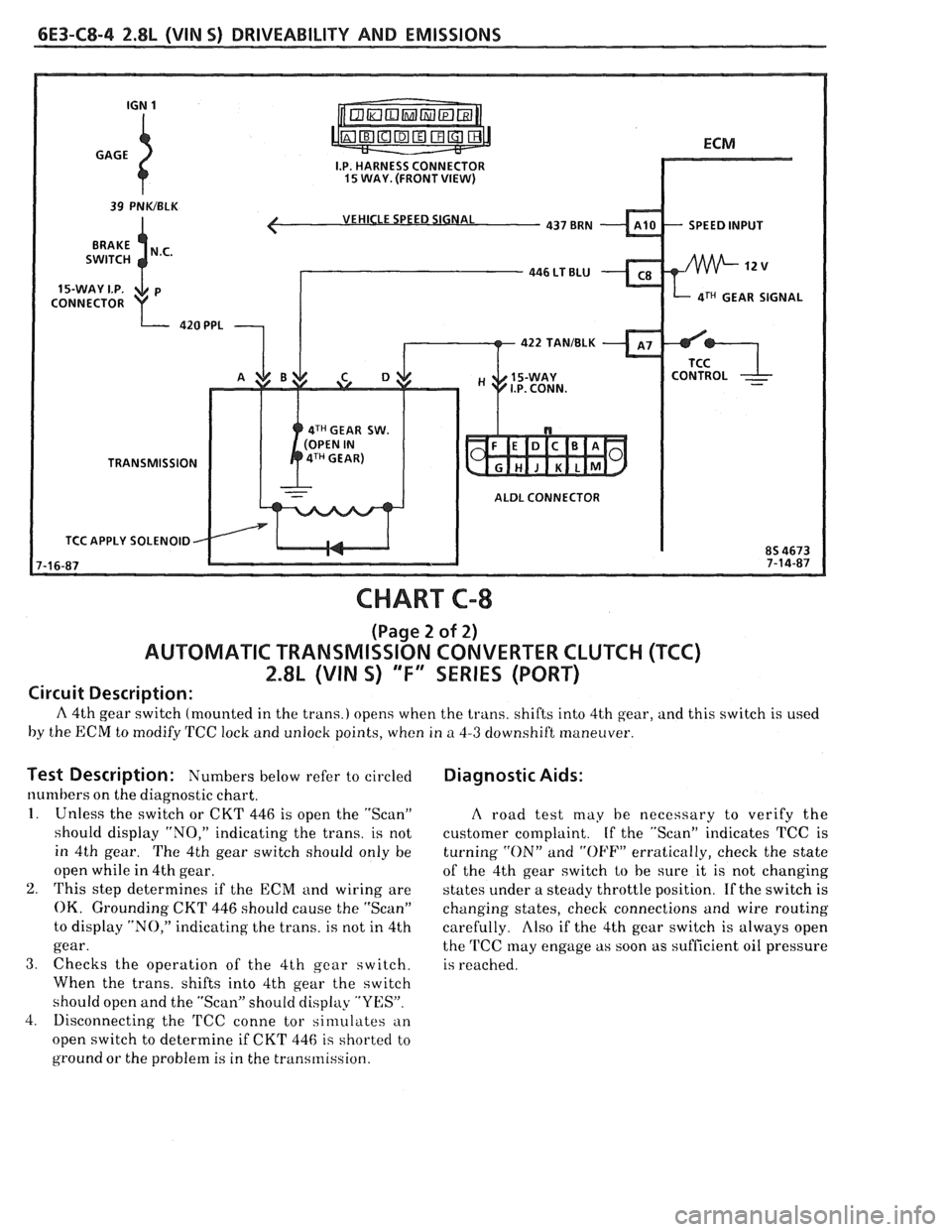
VEHICLE SPEED SIGNAL
4TH GEAR SIGNAL
422 TANIBLK
4TH GEAR SW.
TRANSMISSION
ALDL CONNECTOR
TCC APPLY SOLENOID
CHART C-8
(Page 2 of 2)
AUTOMATIC TRANSMISSION CONVERTER CLUTCH (TCC)
2.8L (VIN S) "F" SERIES (PORT)
Circuit Description:
A 4th gear switch (mounted in the trans.) opens when the trans. shifts into 4th gear, and this switch is used
by the ECM to modify TCC lock and unlock points, when in
a 4-3 downshift maneuver.
Test Description: Numbers I~elow refer to circled
numbers on the diagnostic chart.
1. Unless the switch or CKT 446 is open the "Scan"
should display "NO," indicating the trans. is not
in 4th gear. The 4th gear switch should only be
open while in 4th gear.
2. This step determines if the ECM and wiring are
OK. Grounding CKT 446 should cause the "Scan"
to display "NO," indicating the trans. is not in 4th
gear.
3. Checks the operation of the 4th gear switch.
When the trans. shifts into 4th gear the switch
should open and the "Scan" should display "YES".
4. Disconnecting the
'FCC conne tor sinlulates an
open switch to determine if CKT 446
is shorted to
ground or the problem is in the transmission.
Diagnostic Aids:
A road test may he necessary to verify the
customer complaint. If the "Scan" indicates TCC is
turning
"ON" and "OFF" erratically, check the state
of the 4th gear switch
to be sure it is not changing
states under a steady throttle position. If the switch is
changing states, check connections and wire routing
carefully.
Also if the 4th gear switch is always open
the
'FCC may engage as soon as sufficient oil pressure
is reached.
Page 792 of 1825
DRIVEABILITY AND EMISSIONS 2.8L (VIN S) 6E3-C40-1
SECTION CIO
ECM CONTROLLED AIR CONDlTlOlUlNG
CONXENTS
GENERAL DESCRIPTION ................ C10-1 DIAGNOSIS ......................... C10-1
OPERATION ....................... C10-1 ON-CARSERVICE ..................... C10-1
GENERAL DESCRIPmON
In order to improve idle quality and wide open
throttle performance, the
NC compressor is controlled
by the ECM.
There are two different types of
AJC systems used
in
GM vehicles. One is referred to as C.C.O.T. (cycling
clutch orifice tube), which uses a fixed displacement
compressor. The other type of system uses a
compressor with
a variable displacement, and is
referred to as the V-5 type system. The V-5 type meets
A/C requirements without cycling. For descriptions of
both types, and an explanation of the components
used, refer to Section
"IB" of the service manual.
OPERATION
The 2.8L engine uses the C.C.O.T. type A/C
system, and is controlled by the ECM. When
NC is
requested, 12V power is supplied to the pressure
cycling switch and to the
NC power relay. The ECM
controls the
A/C clutch by energizing the A/C control
relay. This allows the
EChI to incrctlse idle speed
before turning on
NC to improve idle quality. The
high pressure cut-out switch (normally
closed) opens when head pressure gets too high. This
disables the
A/C clutch, before damage can occur to
the system. This switch opens, when pressure is
greater than about 440 psi (3034
kPa).
See CHART C-10 for diagnosis and wiring
diagram of the electrical portion of the
NC circuit.
DIAGNOSIS
CHART C-10 should be used for diagnosing the
electrical portion of the
A/C circuit. Section "1R"
should
be used for diagnosing the refrigerant portion
of the system.
The "Scan" tool will be used in diagnosing the
system, as it has the ability to read the
A/C request
input to the ECM, as well as displaying when the
ECM has commanded the
A/C clutch "ON".
ON-CAR SERVICE
For removal and replacement procedures of NC
components, refer to Section
" 1" of the service manual.
Page 804 of 1825
DRIVEABILITY AND EMISSIONS 5.OL (VIM F) & 5.7L(VIN 8) 6E3-A-1
DIAGNOSIC CIRCUIT CHECK Cold Oxygen Sensor
The "Diagnostic Circuit Check" verifies the On some engines. the Oxygen Sensor will cool off
system is functioning correctly
. Some special after only a short period of operation at idle . This will
considerations to keep in mind while making the put the system into "Open Loop"
. To restore "Closed
"Diagnostic Circuit Check" are:
I. oop" operation. run the engine at part throttle
several minutes and accelerate from idle to part
Blocking Drive Wheels throttle a few times .
The vehicle drive wheels must be blocked while Basic Procedure
checking the system .
If you have not reviewed the Basic Information on
how to use the Diagnostic Procedures. go to the
Introduction of this section
.
SECTION A
ENGINE COMPONENTS
/WIRING DIAGRAMS 1 DIAGNOSTIC CHARTS
........................................................ Component Locations Page A-2
...................................................... Wiring Diagrams. (1 of 4) Page
A-3
ECMTerminal EndView ...................................................... PageA-7
.................................................. Scan Diagnostic Circuit Check Page
A-8
........................................ . No "Service Engine Soon" Light Chart A-I Page A-10
No ALDL Data
. "Service Engine Soon" Light On Steady (Won't Flash Code 12) . Chart A-2 ..... Page A-12
................................... . Engine Cranks But Won't Run Chart A.3, (1 of 2) Page A-14
......................................... Fuel System Diagnosis . Chart A.7, (1 of 2) Page
A-18
.................................................... . Cold Start Valve Chart A-9 Page A-22
..................................................... Code 13 O2 Sensor Circuit Page
A-24
.................................. Code 14 Coolant Temperature Sensor Circuit (High) Page
A-26
.................................. Code 15 Coolant Temperature Sensor Circuit (Low) Page
A-28
................................. Code 2 I Throttle Position Sensor (TPS) Circuit (High) Page
A-30
.................................. Code 22 Throttle Position Sensor (TPS) Circuit (Low) Page
A-32
......................... Code 23 Manifold Air Temperature (MAT) Sensor Circuit (Low) Page
A-34
........................................ Code 24 Vehicle Speed Sensor (VSS) Circuit Page
A-36
......................... Code 25 Manifold Air Temperature (MAT) Sensor Circuit (High) Page
A-38
..................................... Code 32 Exhaust Gas Recirculation (EGR) Circuit Page
A-40
................................... Code 33 Mass Air Flow (MAF) Sensor Circuit (High) Page
A-42
................................... Code 34 Mass Air Flow (MAF) Sensor Circuit (Low) Page
A-44
................................. Code 36 Mass Air Flow (MAF) Sensor Burn-Off Circuit Page
A-46
................................................... Code 41 Cylinder Select Error Page
A-48
...................................... Code 42 Electronic Spark Timing (EST) Circuit Page
A-50
...................................... Code 43 Electronic Spark Control (ESC) Circuit Page
A-52
............................................ Code 44 Oxygen Sensor Circuit (Lean) Page
A-54
............................................. Code 45 Oxygen Sensor Circu~t (Rich) Page
A-56
......................................... Code 46 Vehicle Anti Theft System (VATS) Page
A-58
Code51
MEM.CAL ........................................................... PageA-62
........................................................ Code52CALPAKError PageA-62
................................................... Code 53 System Over Voltage Page
A-62
................................................ Code 54 Fuel Pump Circu~t (Low) Page
2-60
Page 807 of 1825
6E3-A-4 5.OL (VIN F) & 5.7L (VIN 8) DRIVEABILITY AND EMISSIONS
I
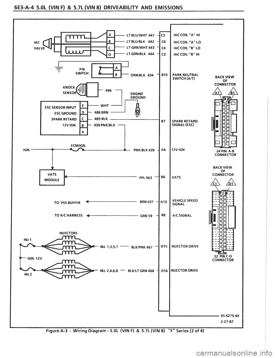
LT BLUNVHT 441 IAC COIL "A" HI
SPARK
RETARD
TO
VSS BUFFER
TO
A/C HARNESS 4
INJ. 1,3,5,7 -
BACK VlEW OF
CONNECTOR
24 PIN A-B
CONNECTOR
BACK
VlEW OF
CONNECTOR
32 PIN C-D
CONNECTOR
2-27-87
Figure A-3 - Wiring Diagram - 5.OL (VIN F) & 5.7L (VIN 8) "F" Series (2 of 4)
Page 808 of 1825
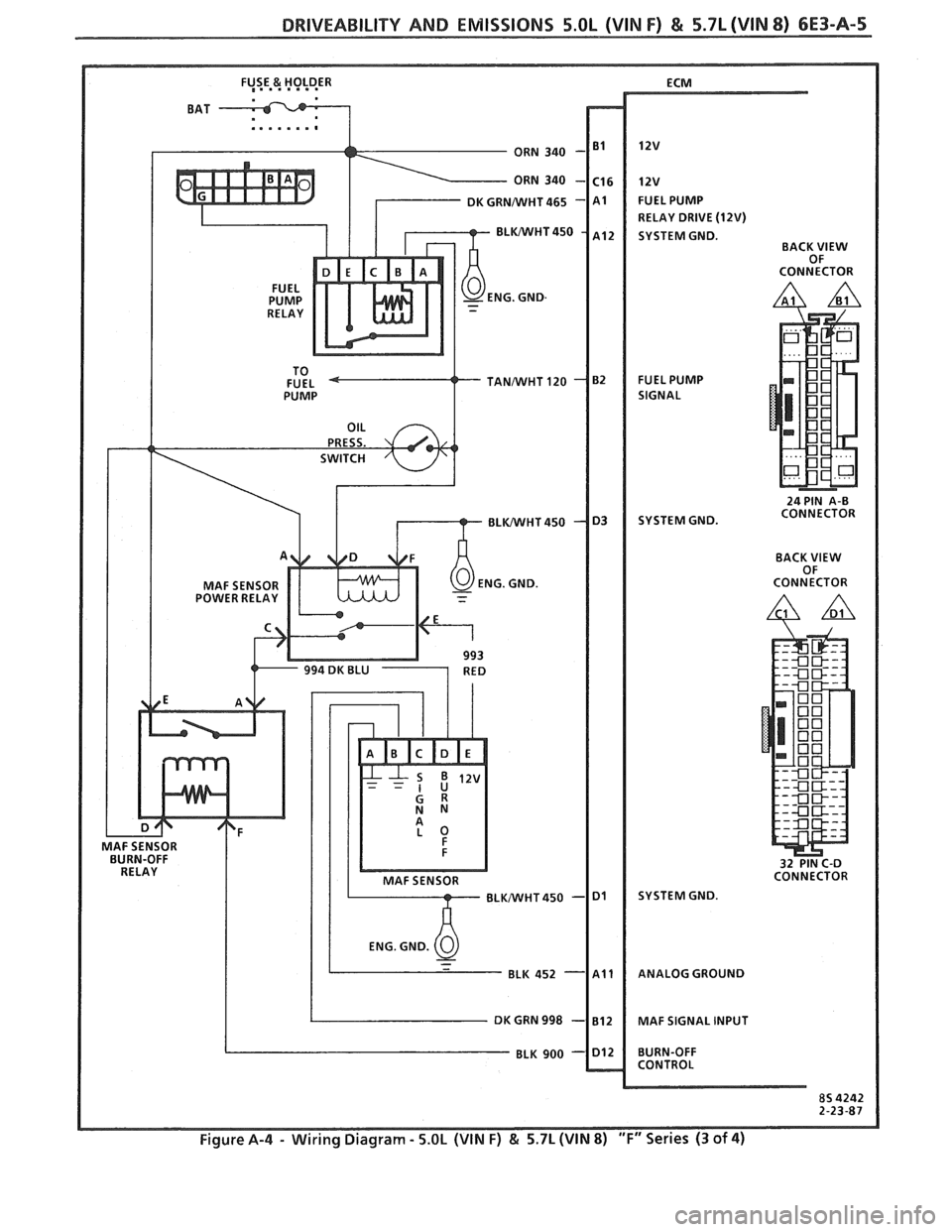
DRIVEABILITY AND EMISSIONS 5.OL (VIN F) & 5.7L(VIN 8) 6E3-A-5
MAF SENSOR
POWER RELAY ECM
12v
FUEL
PUMP
RELAY DRIVE
(12W)
SYSTEM GND.
BACK VlEW
OF
CONNECTOR
FUEL PUMP
SIGNAL
24 PIN A-B
SYSTEM GND. CONNECTOR
BACK
VlEW OF
CONNECTOR
32 PIN C-D
CONNECTOR
SYSTEM GND.
ANALOG GROUND
MAF SIGNAL INPUT
BURN-OFF
CONTROL
Figure A-4 - Wiring Diagram - 5.OL (VIN F) & 5.7L (VIN 8) "F" Series (3 of 4)
Page 815 of 1825
6E3-A-12 5.OL (VIN F) & 5.7L (VIN 8) DRIVEABILITY AND EMISSIONS
TO MAF SENSOR
POWER & BURN-OFF
, . . . . .
439 PNWBLK
419 BRNNVHT
SERIAL DATA
451
WHTIBLK
450 BLKIWHT
ALDL CONNECTOR
CHART A-2
NO ALDL DATA OR WON'T FLASH CODE 12
""SERVICE ENGINE SOON" LIGHT '"ON" STEADY
5.OL (VIN F) & 5.7L (VIN 8) ""FYEERIES (PORT)
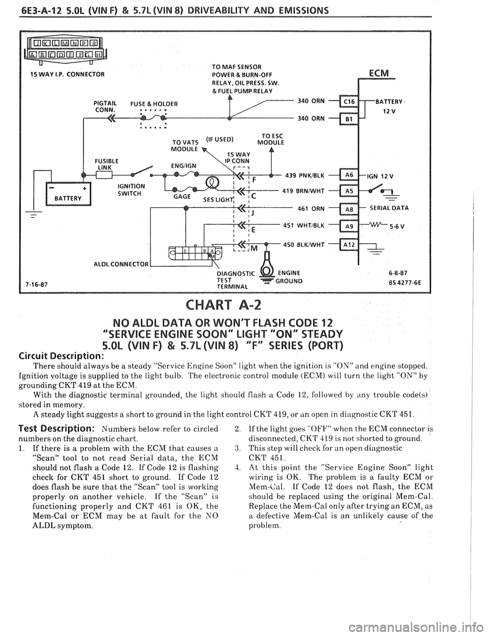
Circuit Description:
'I'here should always be a steady "Service Engine Soon" light when the ignition is "ON" and engine stopped.
Ignition voltage is supplied to the light bulb.
'I'he electronic control module (ECM) will turn the light "ON" by
grounding CKT 419 at the ECM.
With the diagnostic terminal grounded, the light should flash
a Code 12, followed by any trouble code(s)
stored in memory.
A steady light suggests a short to ground in the light control CKT 419, or tin open in cliagnostic CKT 451.
Test Description: Numbers below refer to circled
numbers on the diagnostic chart.
1. If there is a problem with the ECM that causes
a
"Scan" tool to not read Serial data, the ECM
should not flash a Code 12. If Code 12 is flashing
check for CKT 451 short to ground. If Code 12
does flash be sure that the "Scan" tool is working
properly on another vehicle. If the "Scan" is
functioning properly and CKT 461 is OK, the
Mem-Cal or ECM may be at fault for the NO
ALDL symptom. 2.
If
the light goes
"OFF" when the ECM connector is
disconnected,
CK'r 419 is not shorted to ground.
3. This step will check for an open diagnostic
CKT 451.
-2. At this point the "Service Engine Soon" light
wiring is OK. The problem is a faulty ECM or
Mem-Cal. If Code 12 does not flash, the ECM
should be replaced using the original Mem-Cal.
Replace the Mem-Cal only after trying an ECM, as
a defective Mem-Cal is an unlikely cause of the
problem.
Page 827 of 1825
6E3-A-24 5.OL (VIN F) & 5.71 (VIN 8) DRIVEABILITY AND EMISSIONS
OXYGEN ( 02) SENSOR
CODE 13
OXYGEN SENSOR CIRCUIT
(OPEN CIRCUIT)
5.OL (VIN F) & 5.7L (VIN 8) 'T" SERIES (PORT)
Circuit Description:
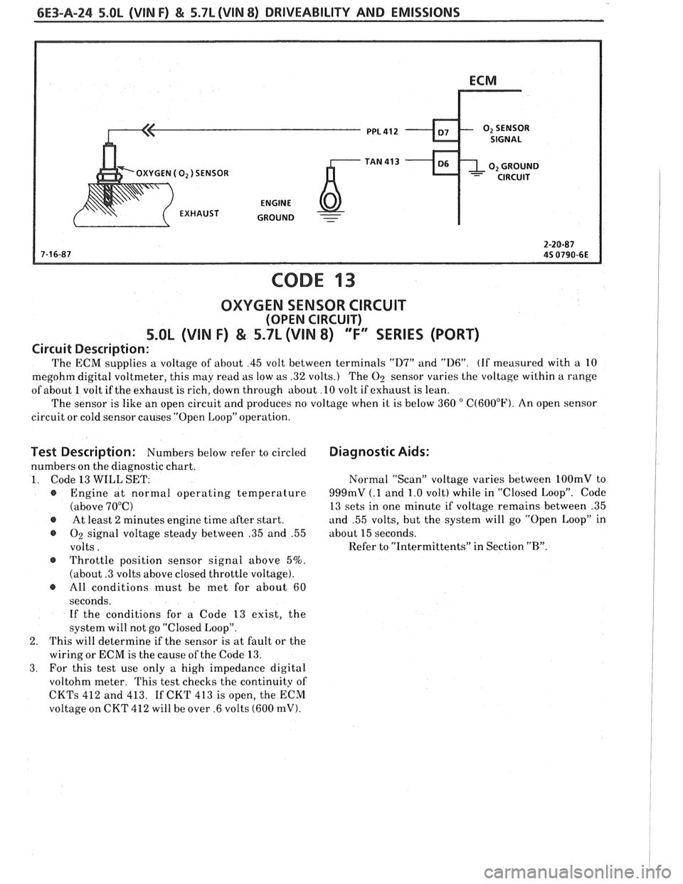
The ECM supplies a voltage of about .45 volt between terminals "D7" and "D6". (If measured with a 10
megohm digital voltmeter, this may read as low as .32 volts.) The
O2 sensor varies the voltage within a range
of about 1 volt if the exhaust is rich, down through about
.l0 volt if exhaust is lean.
The sensor is like an open circuit and produces no voltage when it is below 360
" C(60OoF). An open sensor
circuit or cold sensor causes "Open Loop" operation.
Test Description: Numbers below refer to circled
numbers on the diagnostic chart.
1. Code 13
WILL SET:
@ Engine at normal operating temperature
(above 70°C)
@ At least 2 minutes engine time after start.
@ O2 signal voltage steady between .35 and .55
volts.
@ Throttle position sensor signal above 5%.
(about
.3 volts above closed throttle voltage).
@ All conditions must be met for about 60
seconds. If the conditions for
a Code 13 exist, the
system will not go "Closed Loop".
2. This will determine if the sensor is at fault or the
wiring or ECM is the cause of the Code 13.
3. For this test use only a high impedance digital
voltohm meter. This test checks the continuity of
CKTs 412 and 413. If CKT 413 is open, the ECM
voltage on CKT 412 will be over .6 volts (600 mV).
Diagnostic Aids:
Normal "Scan" voltage varies between 1OOmV to
999mV (.1 and 1.0 volt) while in "Closed Loop". Code
13 sets in one minute if voltage remains between .35
and .55 volts, but the system will go
"Open Loop" in
about
15 seconds.
Refer to "Intermittents" in Section
"B".
Page 831 of 1825
6E3-A-28 S.OL (VIN F) & 5.7L (VIN 8) DRIVEABILITY AND EMISSIONS
COOLANT SENSOR SIGNAL
CODE 15
COOLANT TEMPERATURE SENSOR CIRCUIT
(LOW TEMPERATURE INDICATED)
5.OL (VIN F) & 5.7L (VIN 8) 'Ti' SERIES (PORT)
Circuit Description:
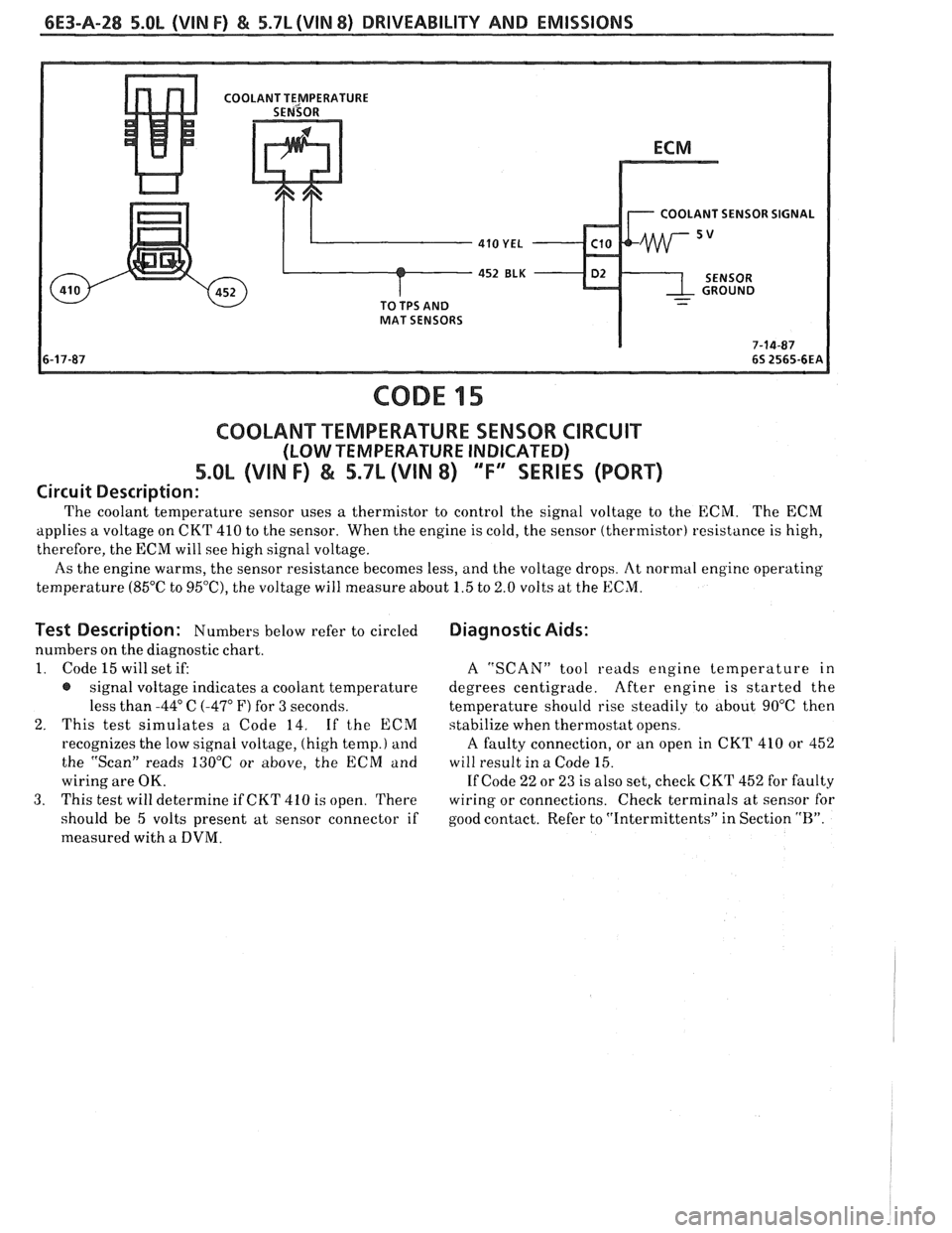
The coolant temperature sensor uses a thermistor to control the signal voltage to the ECM. The ECM
applies a voltage on CKT 410 to the sensor. When the engine is cold, the sensor (thermistor) resistance is high,
therefore, the ECM will see high signal voltage.
As the engine warms, the sensor resistance becomes less, and the voltage drops. At normal engine operating
temperature (85°C to
95'0, the voltage will measure about 1.5 to 2.0 volts at the ECM.
Test Description: Numbers below refer to circled
numbers on the diagnostic chart.
1. Code 15 will set if:
@ signal voltage indicates a coolant temperature
less than
-44" C (-47" F) for 3 seconds.
2. This test simulates a Code 14. If the ECM
recognizes the low signal voltage, (high temp.)
and
the "Scan" reads 130°C or above, the ECM and
wiring are OK.
3. This test will determine if CKT 410 is open. There
should be 5 volts present at sensor connector if
measured with
a DVM.
Diagnostic Aids:
A "SCAN" tool reads engine temperature in
degrees centigrade. After engine is started the
temperature should rise steadily
to about 90°C then
stabilize when thermostat opens.
A faulty connection, or an open in CKT 410 or 452
will result in a Code 15.
If Code 22 or 23 is also set, check CKT 452 for faulty
wiring or connections. Check terminals at sensor for
good contact. Refer to "Intermittents" in Section
"R".