1988 PONTIAC FIERO wiring
[x] Cancel search: wiringPage 923 of 1825
Install or Connect
1. ESC sensor into engine block.
e Tighten to 14 ft. lbs. (19 Nsm).
2. ESC
wiring harness connector to the ESC sensor.
3. Lower car.
4. Negative battery cable.
ESC MODULE AND BRACKET
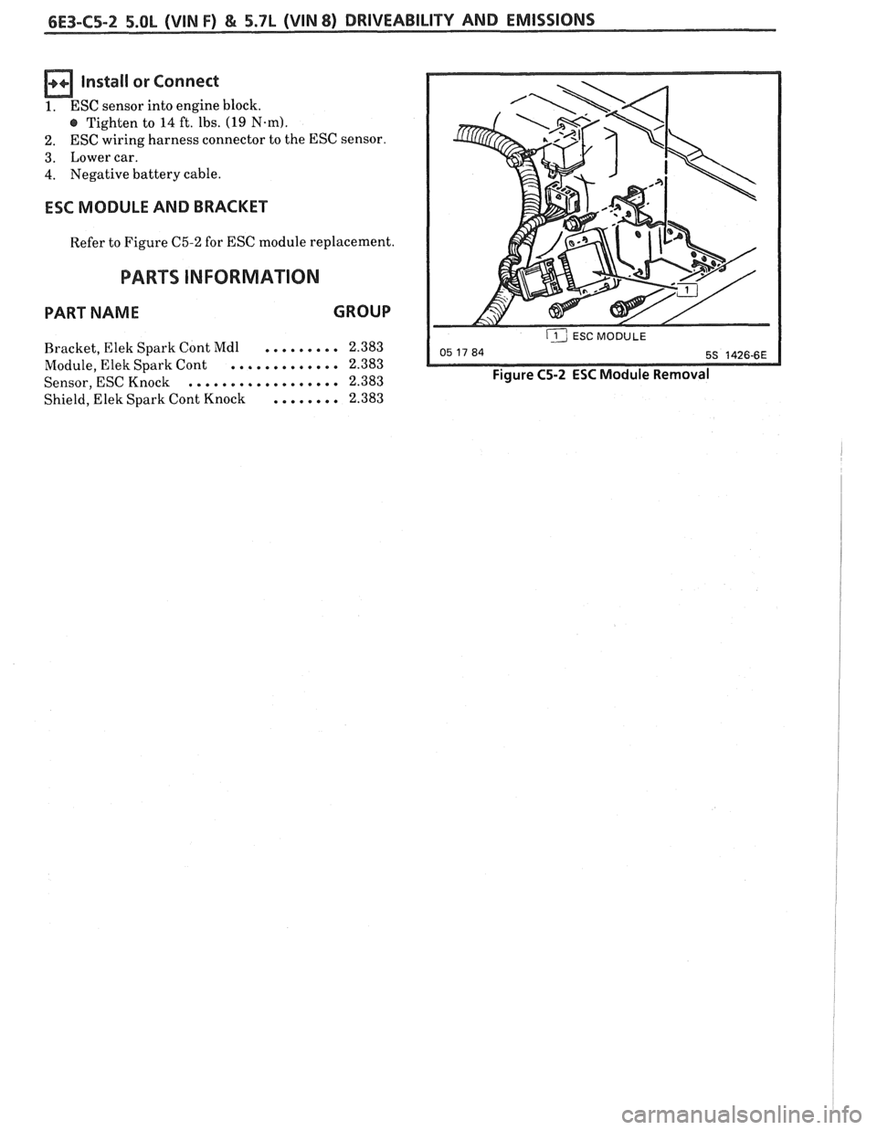
Refer to Figure C5-2 for ESC module replacement.
PARTS INFORMATION
PART NAME GROUP
......... Bracket, Elek Spark Cont Mdl 2.383
............. Module,
Elek Spark Cont 2.383
.................. Sensor, ESC Knock 2.383
Shield, Elek Spark Cont Knock
........ 2.383
ij ESC MODULE --
Figure C5-2 ESC Module Removal
Page 933 of 1825
6E3-C6-6 5.OL (VIN F) & 5.7L (VIN 8) DRIVEABILITY AND EMISSIONS
AIR MANAGEMENT CHECK (PEDES)
5.OL (VIN F) & 5.7L (VIN 8) "F" SERIES (PORT)
Circuit Description:
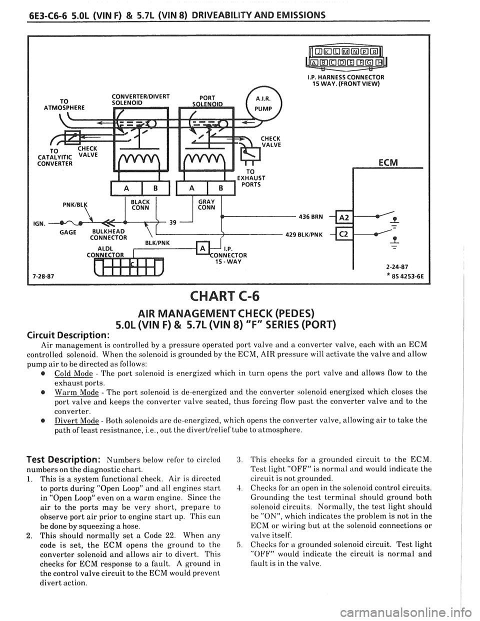
Air management is controlled by a pressure operated port valve and a converter valve, each with an ECM
controlled solenoid. When the solenoid is grounded by the ECM, AIR pressure will activate the valve and allow
pump air to be directed as follows:
@ Cold Mode - The port solenoid is energized which in turn opens the port valve and allows flow to the
exhaust ports.
@ Warm Mode - The port solenoid is de-energized and the converter solenoid energized which closes the
port valve and keeps the converter valve seated, thus forcing flow past the converter valve and to the
converter.
@ Divert Mode - Both solenoids are de-energized, which opens the converter valve, allowing air to take the
path of least resistnance,
i.e., out the di~ertl~elief tube to atmosphere.
Test Description: Numbers below refer to circled
numbers on the diagnostic chart.
1. This is a system functional check. Air is directed
to ports during "Open Loop" and all engines start
in "Open Loop" even on a warm engine. Since the
air to the ports may be very short, prepare to
observe port air prior to engine start up. This can
be done by squeezing a hose.
2. This should normally set a Code 22. When any
code is set, the ECM opens the ground to the
converter solenoid and allows air to divert. This
checks for ECM response to a fault. A ground in
the control valve circuit to the ECM would prevent
divert action.
3. This checks for a grounded circuit to the ECM.
Test light
"OFF" is normal and would indicate the
circuit is not grounded.
4. Checks for an open in the solenoid control circuits.
Grounding the test terminal should ground both
solenoid circuits. Normally, the test light should
be
"ON", which indicates the problem is not in the
ECM or wiring but at the solenoid connections or
valve itself.
5, Checks for a grounded solenoid circuit. Test light
"OFF" would indicate the circuit is normal and
fault is in the valve.
Page 942 of 1825
DWlVEABlLlTV AND EMISSIONS 5.01, QVIN F) & 5.71 (VIN 8) 6E3-C8-1
TRANSMISSION CONVERTER CLUTCH (KC) SYSTEM
AND MANUAL "TRANSMISSION SHlFT LBGH"O"=Ob ONLY
CONTENTS
................ GENERAL DESCRIPTION C8-1 DIAGNOSIS ....................... .. C8-1
........ PURPOSE ......................... CS-1 SHIFT LIGHT (MIT) DESCRIPTION C8-1
....................... OPERATION C8-1 DIAGNOSIS ......................... CS-1
OM-CAR SERVICE ..................... C8-1
GENERAL DESCRIPTION
PURPOSE
The transmission converter clutch (TCC) system
uses
a solenoid operated valve in the automatic
transmission to couple the engine flywheel to the
output shaft of the transmission thru the torque
converter. This reduces the slippage losses in the
converter, which increases fuel economy.
OPERATION
For the converter clutch to apply, two conditions
must be met:
e Internal transmission fluid pressure must be
correct. For information on internal transmission
operation, see Section
"7A". This section will
cover only the electrical operation of the TCC
system.
@ The ECM grounds a switch internally to turn
"ON" a solenoid in the transmission. This moves a
check ball, which will allow the converter clutch
to apply, if the hydraulic pressure is correct, as
described above.
The ECM controls the TCC apply solenoid by
looking at several sensors:
@ Speedo Buffer Sensor (also called Vehicle Speed
Sensor
(VSS) Speed must be above a certain value
before the clutch can apply.
@ Coolant Temperature Sensor Engine must be
warmed
LIP before clutch can apply about 65" C
(149°F).
Throttle Position Sensor (TPS) After the
converter clutch applies, the ECM uses the
information
from the TPS to release the clutch
when the car is accelerating or decelerating at
a
certain rate.
The brake switch
is also part of the 'I'CC circuit as
it will remove battery voltage to the
'FCC solenoid
when the brake pedal is depressed.
@ Gear Select Switch The 4th gear switch is used to
send a signal to the ECM telling it when the
transmission is in 4th
gear
The ECM uses this information to vary the conditions
under which the clutch applies or releases. However,
the transmission does not have to be in fourth gear in
order for the ECM to turn the clutch "ON".
If the converter clutch is applied at all times, the
engine will stall immediately, just as in a manual
transmission with the clutch applied.
If the converter
clutch does not apply, fuel
ecomony may be lower than expected. If the vehicle
speed sensor fails, the TCC will not apply. If the 4th
gear switch does not operate, the TCC may not apply
at the right time.
DIAGNOSIS
The diagnosis of the TCC system is covered in
CHART C-$A. If the ECM detects a problem in the
system, a Code 24 should set. In this case, see Code 24
CHART.
SHIFT LIGHT (MR) DESCRIPTION
The purpose of the shift light is to provide a
display which indicates the optimum fuel economy
point for up shifting the manual transmission based
on engine speed and load. The display is
a lamp on the
instrument panel. Activation
of the ECM driver turns
the lamp "ON".
DIAGNOSIS
The shift light circuit can be checked using
CEIAR'I' C-8B.
ON-CAR SERVICE
See Section "8B" if the shift light bulb needs
replacement.
See Section
"GE" to repair wiring problem.
@ See Section "C- 1" if ECM is to be replaced.
Page 945 of 1825
6E3-C8-4 5.OL (\/IN F) & 5.7b (VIN 8) DRIVEABILITY AND EMISSIONS
15-WAY I.P. CONNECTOR
SPEED INPUT
4TH GEAR SIGNAL
4TH GEAR SW.
TRANSMISSION
ALDL CONNECTOR
APPLY SOLENOID
CHART C-8A
(Page 2 of 2)
TRANSMISSION CONVERTER CLUTCH (TCC) ELECTRICAL DIAGNOSIS
5.OL (VIN F) & 5.7L (VIN 8) "F" XRlES (PORT)
Circuit Description:
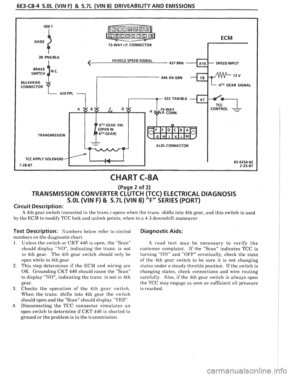
A 4th gear switch (mounted in the trans.) opens when the trans. shifts into 4th gear, and this switch is used
by the ECM to modify TCC lock and unlock points, when in a 4-3 downshift maneuver.
Test Description: Numbers below refer to circled
numbers on the diagnostic chart.
1. Unless the switch or CKT 446 is open, the "Scan"
should display "NOJ', indicating the trans. is not
in 4th gear. The 4th gear switch should only he
open while in 4th gear.
2. This step determines if the ECM and wiring are
OK. Grounding CKT 446 should cause the "Scan"
to display "NO", indicating the trans. is not in 4th
gear.
3. Checks the operation of the 4th gear switch.
When the trans, shifts into 4th gear the switch
should open and the "Scan" should display "YES".
4. Disconnecting the TCC connector sin~ulates an
open switch to determine if CKT 446 is shorted to
ground or the problem is in the transmission.
Diagnostic Aids:
A road test may be necessary to verify the
customer complaint.
If the "Scan" indicates TCC is
turning
"ON" and "OFF" erratically, check the state
of the 4th gear switch to be sure it is not changing
states under a steady throttle position. If the switch is
changing states, check connections and wire routing
carefully. Also, if the 4th gear switch is always open
the
'l'CC may engage as soon as sufficient oil pressure
is reached.
Page 947 of 1825
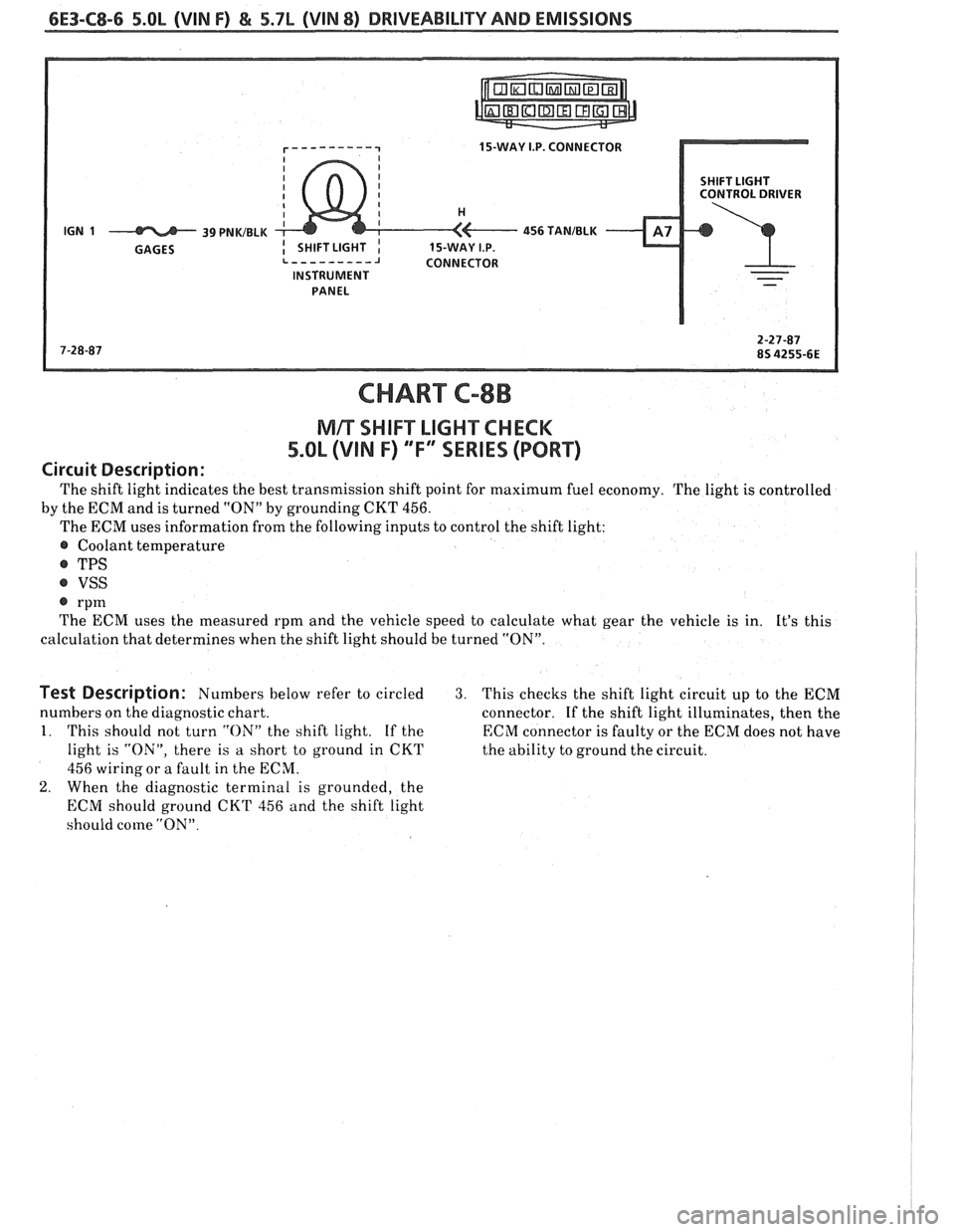
6E3-C8-6 5.OL (VIN F) & 5.7L (WIN 8) DRIVEABILITY AND EMISSIONS
15-WAY I.P. CONNECTOR
SHIFT LIGHT
CONTROL DRIVER
INSTRUMENT PANEL
CHART C-8B
NlR SI-IIFT LIGHT CHECK
5.OL (VIN F) "F" "SERIES (PORT)
Circuit Description:
The shift light indicates the best transmission shift point for maximum fuel economy. The light is controlled
by the ECM and is turned
"ON" by grounding CKT 456.
The ECM uses information from the following inputs to control the shift light:
@ Coolant temperature
@ TPS
@ VSS
@ rpm
The ECM uses the measured rpm and the vehicle speed to calculate what gear the vehicle is in. It's this
calculation that determines when the shift light should be turned "ON".
Test Description: Numbers below refer to circled 3. This checks the shift light circuit up to the ECM
numbers on the diagnostic chart.
connector.
If the shift light illuminates, then the
1. This should not turn "ON" the shift light. If the ECM connector is faulty or the ECM does not have
light is "ON", there is a short to ground in CKT
the ability to ground the circuit.
456 wiring or a fault in the ECM.
2. When the diagnostic terminal is grounded, the
ECM should ground
CKT 456 and the shift light
should come
"ON".
Page 959 of 1825
INDEX
SECTION PAGE
Cooling Fan Control
................. General Description C12-1
........................ Diagnosis C12-2
........................... Cuts Out B-5
................... Cylinder Select Error A-48
.................... Deceleration Mode C2-3
......................... Detonation B-4
..................... Dieseling. Run On B-6
............. Distributor Reference Signal C1-4
...................... ECM Terminals A-7
.................. ECM Wiring Diagram A3-A6
EGR Control Valve
................. General Description C7-1
................. Valve Identification C7-2
................... Diagnosis. Service C7-2
A-40
.................. EGR Control Solenoid C7-3
......................... EGR Check C7-4
Electronic Control Module
................. General Description C1-1
......................... Diagnosis C1-4
............................ Service C1-5
..................... Function Check C1-7
Electronic Spark Control (ESC) System
................. General Description C5-1
................... Diagnosis. Service C5-4
Electronic Spark Timing EST
............. A-50
A-52
Engine Cranks But Won't Run
............ A-14
........................ Engine Knock C5-4
.......................... ESC Module C5-2
.......................... ESC Sensor C5-1
.................... ESC System Check C5-4
................... ESTllgnition System C4-1
Evaporative Emission Control System
................. General Description C3-1
.......................... Diagnosis C3-2
Exhaust Emissions Excessive (Odors)
....... B-7
Exhaust Gas Recirculation (EGR) System
.... C7-1
Exhaust System Check Restricted
......... B-8
Fuel Control System
................. General Description C2- 1
......................... Diagnosis C2-5
..................... Fuel Cutoff Mode C2-3
SECTION PAGE
Fuel Injectors ........................
Fuel Pressure Connection Assy ............
Fuel Pressure Relief Procedure ...........
Fuel Pump Electrical Circuit .............
Fuel Pump Relay ......................
Fuel Rail
General Description
.................
........................... Service
Fuel System Diagnosis
..................
Fuel System Pressure Test ...............
Fuel Tank Pressure Control Valve .........
.......................... Hard Start B-2
.......... HE1 High Energy Ignition System C4-1
.......................... Hesitation
B-3
............ Idle Air Control System Check C2-20
.................. Idle Air
Control Valve C2-4
......................... Diagnosis C2-5
.................... Ignition System EST C4-1
........ Ignition System Check Integral Coil C4-4
........................ Incorrect Idle B-6
.................. Information Sensors C1.2. 9
.................. Injector
Balance Test C2-18
........................ lntermittents B-2
........................ Knock Sensor C1-3
........................ Lack Of Power B-4
......... Light. Manual Transmission Shift C8-6
.............. Light. Service Engine Soon A-10
MAF Sensor
.................. General Description C1-2
.......................... Diagnosis C1-5
A.42.44. 46
............................ Service C1-8
... Manual Transmission Electrical Diagnosis C8-10
MAT Sensor
.................. General Description C1-2
......................... Diagnosis C1-5
A.34. 38
Page 960 of 1825
INDEX
SECTION
PAGE
MEM -Cal
General Description ................. C1-I
Diagnosis ......................... C1-4
A-60
Service
........................... C1-6
Functional Check
................... C1-7
Minimum
Idle Speed Adjustment ......... C2-12
Misses ............................. 8-5
Negative Backpressure Valve ............ C7-2
No ALDL Data
....................... A- 12
No "Service Engine Soon" Light
.......... A-10
.................... Oil Pressure Switch C2-16
Oxygen Sensor
General Description
.................. C1-3
......................... Diagnosis C1-5
A.24.54. 56
........................... Service C1-8
Park Neutral Switch
General Description
................. C1-3
Diagnosis
.......................... C1-10
C1-5
Service
........................... C1-9
Poor Fuel Economy
.................... B.6.
C5-4
Poor Performance
.................... C5-4
Positive Crankcase Ventilation (PCV)
General Description. Diagnosis
......... C13-1
Service
............................ C13-2
Pressure Regulator
.................... C2-4
........................ Quad Drivers C 1-4
..................... Reference Signal C1-5
.......................... Rough Idle B-6
RunMode .......................... C2-2
RunOn ............................. B-6
SECTION PAGE
................... Sensor Information C1-2-9
"Service Engine Soon" Light On Steady .... A- 12
................... Setting Timing ... . C4-2
.......................... Shift Light C8-6
Sluggish
............................ B-4
......................... Spark Knock B-4
........................ Speed Sensor C8-2
.................. Speedo Buffer Sensor C8-4
Spongy
............................. B-4
............................ Stalling B-6
........................ Starting Mode C2-2
........................... Stumble B-3
Surges
............................. B-3
.................. System Over Voltage A-60
Throttle Body Unit
................. General Description C2-3
........................... Service C2-11
Throttle Position Sensor
................. General Description C1-3
......................... Diagnosis C1-5
A-30
....................... Adjustments C2-12
........................... Service C1-8
Transmission Converter Clutch TCC System
.................. General Description C8-1
......................... Diagnosis C8.2. 4
U
........................ Unstable Idle B-6
V
...................... Vapor Canister C3-1
Vehicle Speed Sensor
.................. General Description C1-3
.......................... Diagnosis C1-5
A-36
Vehicle Anti-Theft System (VATS)
................. General Description A-58
......................... Diagnosis A-59
W
...................... Wiring Diagrams A-3
................... Won't Flash Code 12 A-
12
Sag
.................+............. B-3
......................... "Scan" Data A-8
Page 962 of 1825
DRIVEABILITY AND EMISSIONS . FUEL INJECIION 6E-1
DRBVEABILIW AND EMISSIONS
CONEENTS
General Information . Section 6E
Driveability and Emissions . Fuel Injected (TBI) . Section 6EZ
Driveability and Emissions . Fuel injected (PORT) . Section 6E3
..................... DRIVEABILITY 6E-1
........................ EMISSIONS 6E-1
MAINTENANCE SCHEDULE ............ 6E-1
VEHICLE EMISSIONS CONTROL
............. INFORMATION UBEL 6E-3
.................... INTRODUCTION 6E-3
.......... Electronic Engine Control 6E-3
What This Section Contains .......*. 6E-3
............. Blocking Drive Wheels 6E-3
.............. Cold Oxygen Sensor 6E-3
VISUAUPHYSICAL UNDERWOOD
..................... INSPECTION 6E-3
BASIC KNOWLEDGE REQUIRED ........ 6E-3
.............. Basic Electric Circuits 6E-3
Use of Circuit Testing Tools ......... 6E-4
Use of Digital Volt-Ohm Meter (DVM) . . 6E-4
DIAGNOSTIC INFORMATION .......... 6E-4
"Service Engine Soon" Light ........ 6E-4
Intermit . "Service Engine Soon" Light . . 6E-4
................... Trouble Codes 6E-4
.................. ALDL Connector 6E-4
Diagnostic Mode ................. 6E-4
Field Service Mode ................ 6E-5
............ Clearing Trouble Codes 6E-5
............. ECM Learning Ability 6E-5
DRIVEABILITY AND EMISSIONS ......... 6E-5
SECTIONS 6E2 and 6E3 SUMMARY ...... 6E-5
SECTION A ....................... 6E-6
Diagnostic Procedure Summary ...... 6E-6
ALDL "SCAN" TOOLS ................ 6E-6
Normal (Open) Mode ............. 6E-6
ALDL (1 OK. or Special) Mode ......... 6E-7
Factory Test (Backup or 3.9K) Mode .... 6E-7
DRIVEABILITY
The driveability diagnosis procedures apply to
various systems in current GM vehicles
. The
procedures assume that the vehicle worked right at
one time and the problem is due to time, wear. dirt or
other causes
. Start with the introduction that follows .
This will describe a systematic diagnostic procedure .
Any system disconnected during diagnosis should
be reconnected
. This includes wires, hoses. linkage.
etc . When removing air cleaner. plug hose fittings
that could cause an air leak
.
"SCAN" TOOLS LIMITATIONS AND USE ... 6E-7
Intermittent Conditions ........... 6E-7
"SCAN" TOOL POSITIONS ............ 6E-7
SECTION B . DRIVEABILITY SYMPTOMS . . 6E-10
SECTION C- COMPONENT SYSTEMS ..... 6E-10
Electronic Control Module (ECM) ..... 6E-10
Fuel Control System ............... 6E-10
Electric Fuel Pump (In-tank) ........ 6E-10
....... Evaporative Emission Control 6E-10
Electronic Spark Timing (EST) ....... 6E-10
....... Electronic Spark Control (ESC) 6E-10
Air Injection Reaction (A.I.R.). ........ 6E-10
......... Early Fuel Evaporation (EFE) 6E-10
Exhaust Gas Recirculation (EGR) ...... 6E-11
Transmission Convefler Clutch (TCC) . . 6E-11
.............. Shift Light Control ; . 6E-I I
................ NC Clutch Control 6E-11
........ Electric Cooling Fan Control 6E-11
Positive Crankcase Ventilation (PCV)
...... or Crankcase Ventilation (CV) 6E-11
Thermostatic Air Cleaner (THERMAC) . . 6E-11
ABBREVIATIONS & GLOSSARY OF TERMS .. 6E-1 1
............ WIRING HARNESS SERVICE 6E-14
......................... GENERAL 6E-14
WIREHARNESS.... ............*.... 6E-15
CONNECTORS .....e..e..ee...~.e.. 6E-15
................... Weather-Pack 6E-15
.................. Compact Three 6E-16
Metri-Pack Series 150 . Terrn'l Removal 6E-16
...................... Micro-Pack 6E-16
...... TOOLS NEED TO SERVICE SYSTEM 6E-17
GENERAL SPECIFICATIONS ............. 6E-23
EMISSIONS
The exhaust emission control systems used on
General Motors engines perform a specific function to
lower exhaust emissions while maintaining good fuel
economy and driveability
.
MAINTENANCE SCHEDULE
Refer to the General Motors Maintenance
Schedule in Section
"OB" of the Chassis Service
Manual for the maintenance service that should be
performed to retain emission control performance
.