1988 PONTIAC FIERO wiring
[x] Cancel search: wiringPage 1185 of 1825
TROUBLESHOOTING TESTS
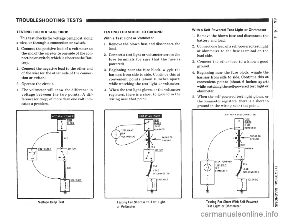
TESTING FOR VOLTAGE DROP
This test checks for voltage being lost along
a wire, or through a connection or switch.
1. Connect the positive lead of a voltmeter to
the end of the wire (or to one side of the con-
nection or switch) which
is closer to the Bat-
tery.
2. Connect the negative lead to the other end
of the wire (or the other side of the connec-
tion or switch).
3. Operate the circuit.
4. The voltmeter will show the difference in
voltage between the two points.
A dif-
ference (or drop) of more than one volt indi-
cates a problem.
Voltage Drop Test
TESTING FOR SHORT TO GROUND
With
a Test Light or Voltmeter
1. Remove the blown fuse and disconnect the
load.
2. Connect a test light or voltmeter across the
fuse terminals (be sure that the fuse is
powered).
3. Beginning near the fuse block, wiggle the
harness from side to side. Continue this at
convenient points (about
6 inches apart)
while watching the test light or voltmeter.
4. When the test light glows, or the \voltmeter
registers. there is a short to ground in the
wiring near that point.
Testing For Short With Test Light
or Voltmeter
With a Self-Powered Test Light or Ohmmeter
1. Remove the blown fuse and disconnect the
battery and load.
2. Connect one lead of a self-powered test light
or ohmmeter to the fuse terminal on the
load side.
3. Connect the other lead to a known good
ground.
4. Beginning near the fuse block, wiggle the
harness from side to side. Continue
this at
convenient points (about
6 inches apart)
while watching the self-powered test light or
ohmmeter.
,5. M'hen the self-powered test light glows, or
the ohmmeter registers. there is a short to
ground in the wiring near that point.
SELF POWERED
DISCONNECTED
Testing For Short With Self-Powered
Test Light or Ohmmeter
Page 1186 of 1825
TROUBLESHOOTING TESTS m r rn 0
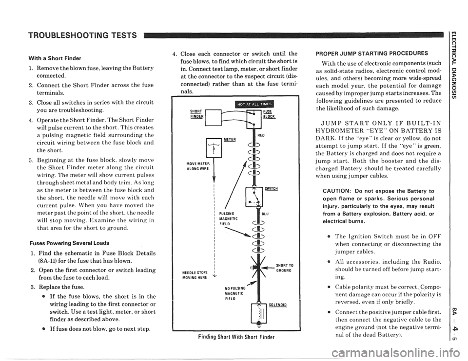
With a Short Finder
1. Remove the blown fuse, leaving the Battery
connected.
2. Connect the Short Finder across the fuse
terminals.
3. Close all switches in series with the circuit
you are troubleshooting.
4. Operate the Short Finder. The Short Finder
will pulse current to the short. This creates
a pulsing magnetic field surrounding the
circuit wiring between the fuse block and
the short.
5. Beginning at the fuse block. slowly move
the Short Finder meter along the circuit
wiring. The meter will show current pulses
through sheet
inetal and body trim. As long
as the meter is between the fuse block and
the short, the needle will move with each
current pulse. When you have
moved the
meter past the point of the short. the needle
will stop
moving. Examine the wiring in
that area for the short to ground.
Fuses Powering Several Loads
1. Find the schematic in Fuse Block Details
(8A-11) for the fuse that has blown.
2. Open the first connector or switch leading
from the fuse to each load.
3. Replace the fuse.
@ If the fuse blows, the short is in the
wiring leading to the first connector or
switch. Use a test light, meter, or short
finder as described above.
@ If fuse does not blow, go to next step.
4. Close each connector or switch until the PROPER JUMP STARTING PROCEDURES
fuse blows, to find which circuit the short is
With the use of electronic components (such
in. Connect test lamp, meter, or short finder
as solid-state radios, electronic control
mod- at the connector to the suspect circuit (dis- ules, and others) becoming more wide-spread
connected) rather than at the fuse termi- each model year, the potential for damage nals. caused by improper jump starts increases. The
SHORT FUSE FINDER - BLOCK -
MOVE METER
NEEDLE STOPS
MOVING HERE
NO PULSING
MAGNETIC
FIELD
Cb
SHORT TO
GROUND
w-
Finding Short With Short Finder
following guidelines are presented to reduce
the likelihood of such damage.
JUMP START ONLY IF BUILT-IN
HYDROMETER "EYE" ON BATTERY IS
DARK. If the "eye" is clear or yellow, do not
attempt to jump start. If the "eye" is green,
the Battery is charged and does not require a
jump start. Both the booster and the dis-
charged Battery should be treated carefully
when using jumper cables.
CAUTION: Do not expose the Battery to
open flame or sparks. Serious personal
injury, particularly
to the eyes, may result
from
a Battery explosion, Battery acid, or
electrical burns.
The Ignition Switch must be in OFF
when connecting or disconnecting the
jumper cables.
All accessories. including the Radio.
should be turned off before jump start-
ing.
Cable polarity must be correct. Compo-
nent damage can occur
if the polarity is
re~~ersed. even if only briefly.
a Connect the positive jumper cable first.
then connect the negative cable to the
engine ground (not the negative termi-
nal of the dead Battery).
Page 1187 of 1825
REPAIR PROCEDURES 0) B
ELECTRICAL REPAIRS
This section provides instruction in the fol-
lowing repairs:
- Circuit Protection
- Typical Electrical Repairs
- Splicing Copper Wire
- Splicing Aluminum \l.ire
- Splicing Txisted Shielded Cable
- Repairing Connectors (Except Weather
Pack
V and
- Repairing breather I'ack * (Environmen-
tal) Connectors
Note: After any electrical repair is made, always
test the circuit by operating the devices in the
circuit. This confirms not only that the repair is
correct, but also that the cause of the complaint
was correctly identified.
CIRCUIT PROTECTION
All electrical circuits are protected against
excessive loads which might occur because of
shorts or overloads in the wiring system. Such
protection is
prolrided by a fuse. circuit
breaker. or fusible link.
Fuses
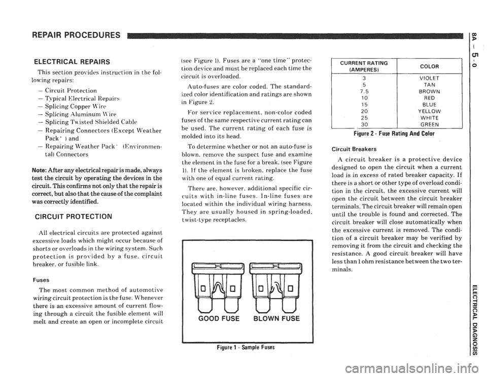
The most common method of automotive
wiring circuit protection is the fuse. Whenever
there is an excessive amount of current flow-
ing through a circuit the fusible element will
melt and create an open or incomplete circuit (see
Figure
1). Fuses are a "one time" protec-
tion device and must be replaced each time the
circuit is overloaded.
Auto-fuses are color coded. The standard-
ized color identification and ratings are shown
in Figure
2.
For senrice replacement. non-color coded
fuses of the same respective current rating can
be used. The current rating of each fuse is
molded into its head.
To determine whether or not an auto-fuse is
blown, remove the suspect fuse and examine
the element in the fuse for a break, (see Figure
1). If the element is broken, replace the fuse
with one of equal current rating.
There are, however. additional specific cir-
cuits with in-line fuses. In-line fuses are
located within the individual wiring harness.
They are usually housed in spring-loaded,
twist-type receptacles.
GOOD FUSE BLOWN FUSE
Figure 1 - Sample Fuses Figure
2 - Fuse Rating And Galor
CURRENT
RATING
(AMPERES)
3
5
7.5
10
15
20
2
5
30
Circuit Breakers
COLOR
VIOLET
TA N
BROWN RED
BLUE
YELLOW
WHITE
GREEN
A circuit breaker is a protective device
designed to open the circuit when a current
load is in excess of rated breaker capacity. If
there is a short or other type of overload condi-
tion in the circuit, the excessive current will
open the circuit between the circuit breaker
terminals. The circuit breaker will remain open
until the trouble is found and corrected. The
circuit breaker will close automatically when
the excessive current is removed. The condi-
tion of a circuit breaker may be verified by
removing it from the circuit and checking the
resistance.
A good circuit breaker will have
less than
1 ohm resistance between the two ter-
minals.
Page 1188 of 1825
REPAIR PROCEDURES
Fusible Links
In addition to circuit breakers and fuses,
some circuits use fusible links to protect the
wiring. Like fuses, fusible links are "one time
"
protection devices that will melt and create an
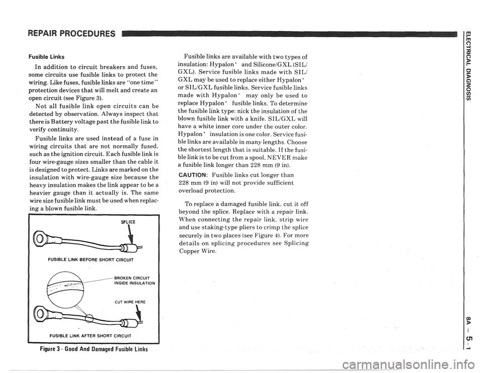
open circuit (see Figure
3).
Not all fusible link open circuits can be
detected by observation. Always inspect that
there is Battery voltage past the fusible link to
verify continuity.
Fusible links are used instead of a fuse in
wiring circuits that are not normally fused,
such as the ignition circuit. Each fusible link is
four wire-gauge sizes smaller than the cable it
is designed to protect. Links are marked on the
insulation with wire-gauge size because the
heavy insulation makes the link appear to be a
heavier gauge than it actually is. The same
wire size fusible link must be used when replac-
ing a blown fusible link.
FUSIBLE LINK BEFORE SHORT CIRCUIT
, BROKEN CIRCUIT INSIDE INSULATION
Fusible links are available with two types of
insulation: Hypalon
bnd SiliconelGXL (SILI
GXL). Service fusible links made with SILI
GXL may be used to replace either Hypalon "
or SILIGXL fusible links. Service fusible links
made with
Hypalonday only be used to
replace Hypalon
"fusible links. To determine
the fusible link type: nick the insulation of the
blown fusible link with a knife.
SILIGXL will
have a white inner core under the outer color.
Hypalon
"nsulation is one color. Service fusi-
ble links are available in many lengths. Choose
the shortest length that is suitable.
If the fusi-
ble link is to be cut from a spool, NEVER make
a fusible link longer than 228 mm
(9 in).
CAUTION: Fusible links cut longer than
228 mm
(9 in) will not provide sufficient
overload protection.
To replace a damaged fusible link, cut it off
beyond the splice. Replace with a repair link.
When connecting the repair link. strip wire
and use staking-type pliers to crimp the splice
securely in two places (see Figure
4). For more
details on splicing procedures see Splicing
Copper Wire.
R SHORT CIRCUIT
Figure 3 - Good And Damaged Fusible Links
-- - - - - -- - - - - -- - - -
Page 1193 of 1825
REPAIR PROCEDURES
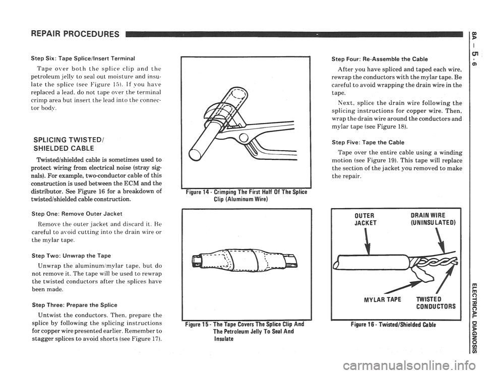
Step Six: Tape Splicellnsert Terminal
Tape over both the splice clip and the
petroleun~ jelly to seal out moisture and insu-
late the splice (see Figure
15). If you have
replaced a lead. do not tape over the terminal
crimp area but insert the lead into the connec-
tor body.
SPLICING TWISTED1
SHIELDED CABLE
ltyistedshielded cable is sometimes used to
protect wiring from electrical noise (stray sig-
nals). For example, two-conductor cable of this
construction is used between the
ECM and the
distributor. See Figure
16 for a breakdown of
twistedshielded cable construction.
Step One: Remove Outer Jacket
Remove the outer jacket and discard it. He
careful to avoid cutting into the drain wire or
the mylar tape.
Step Two: Unwrap the Tape
Unwrap the aluminumlmylar tape, but do
not remove it. The tape will be used to rewrap
the twisted conductors after the splices have
been made.
Step Three: Prepare the Splice
Untwist the conductors. Then, prepare the
splice by following the splicing instructions
for copper wire presented earlier. Remember to
stagger splices to avoid shorts (see Figure
17).
Figure 14 - Crimping The First Half Of The Splice
Clip (Aluminum Wire)
Figure
15 - The Tape Covers The Splice Clip And
The Petroleum Jelly To Seal And
Insulate
Step Four: Re-Assemble the Cable
After you have spliced and taped each wire,
rewrap the conductors with the mylar tape. Be
careful to avoid wrapping the drain wire in the
tape.
Next, splice the drain wire following the
splicing instructions for copper wire. Then,
wrap the drain wire around the conductors and
mylar tape
(see Figure 18).
Step Five: Tape the Cable
Tape over the entire cable using a winding
motion (see Figure
19). This tape will replace
the section of the jacket you removed to make
the repair.
DRAIN WIRE
(UNINSU LATED)
MYLAR TAPE TVVlSTED
CONDUCTORS
Figure
16 - TwistedIShielded Cable
Page 1209 of 1825
POWER DISTRIBUTION
CIRCUIT OPERATION
Electrical power for the car is provided by the
Generator when the engine is running. The
schematic diagram shows how each circuit gets
its power. For more details about the Gener-
ator, and connections to the Battery and
Starter, see Starter and Charging System, Sec-
tion
8A-30.
The car's Power Distribution System con-
sists of Fusible Links, Fuses, Circuit Breakers,
the Light Switch and the Ignition Switch. Fusi-
ble Links are short pieces of wire to which they
supply power. They are covered with a special
high-temperature insulation. When conducting
a high current, the Fusible Link will melt and
stop current flow. They are designed to protect
the car's electrical system from electrical
shorts where it is not protected by the Circuit
Breakers and Fuses. See Fuse Block Details
and Light Switch Details for complete wiring to
the first component in each circuit.
The Ignition Switch has six positions, five of
which have detents. The BULB TEST position
is after the RUN position and just before the
START position. BULB TEST does not have a
detent. As shown in the schematic, circuits
which are supplied from the Ignition Switch are
On (Hot) for different switch positions. Indi-
vidual schematics show their fuses supplied
from headings such as "Not In Run. "The head-
ing corresponds to the Ignition Switch position
in which power is On.
Page 1304 of 1825
STARTER AND CHARGING SYSTEM
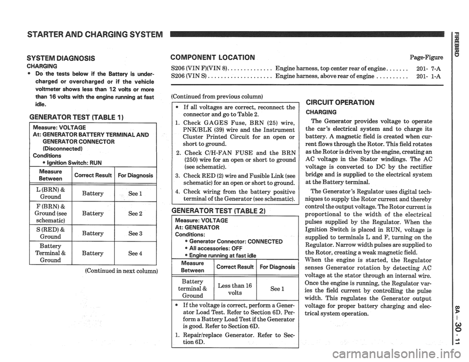
SYSTEM DIAGNOSIS
CHARGING Do the tests below if the Battery is under-
charged or overcharged or if the vehicle
voltmeter shows less than
12 volts or more
than
16 volts with the engine running at fast
idle.
GENERATOR TEST (TABLE 1)
GENERATOR CONNECTOR
(Continued in next column)
COMPONENT LOCATION Page-Figure
...... S206 (VIN F)(VIN 8). ............. Engine harness, top center rear of engine.
201- 7-A
.......... S206 (VIN S) .................... Engine harness, above rear of engine
201- 1-A
(Continued from previous column)
If
all voltages are correct, reconnect the
connector and go to Table 2.
1. Check GAGES Fuse, BRN (25) wire,
PNKIBLK (39) wire and the Instrument
Cluster Printed Circuit for an open or
short to ground.
2. Check
CIH-FAN FUSE and the BRN
(250) wire for an open or short to ground
(see schematic).
3. Check RED (2) wire and Fusible Link (see
schematic) for an open or short to ground.
4. Check wiring from the battery positive
terminal of the Generator (see schematic).
GENERATOR TEST (TABLE 2)
Measure: VOLTAGE
At: GENERATOR
Conditions: Generator Connector: CONNECTED
All accessories: OFF
Engine running at fast idle
Measure I Correct Resuk I For Diagnosis / 1 Between
Battery
terminal
& Less than 16
1 Ground 1 1 See 1
If the voltage is correct, perform a Gener-
ator Load Test. Refer to Section 6D. Per-
form a Battery Load Test if the Generator
is good. Refer to Section 6D.
1. Repairlreplace Generator. Refer to Sec-
tion 6D.
CIRCUIT OPERATION
CHARGING
The Generator provides voltage to operate
the car's electrical system and to charge its
battery. A magnetic field is created when cur-
rent flows through the Rotor. This field rotates
as the Rotor is driven by the engine, creating an
AC voltage in the Stator windings. The AC
voltage is converted to DC by the rectifier
bridge and is supplied to the electrical system
at the Battery ter
The Generator's Regulator uses digital tech-
niques to supply the Rotor current and thereby
control the output voltage. The Rotor current is
proportional to the width of the electrical
pulses supplied by the Regulator. When the
Ignition Switch is placed in RUN, voltage is
supplied to terminals L and F, turning on the
Regulator. Narrow width pulses are supplied to
the Rotor, creating a weak magnetic field.
When the engine is started, the Regulator
senses Generator rotation by detecting
AC
voltage at the stator through an internal wire.
Once the engine is running, the Regulator var-
ies the field current by controlling the pulse
width. This regulates the Generator output
voltage for proper battery charging and elec-
trical system operation.
Page 1361 of 1825
AIR CONDITIONING: COMPRESSOR CONTROLS
C60, MANUAL
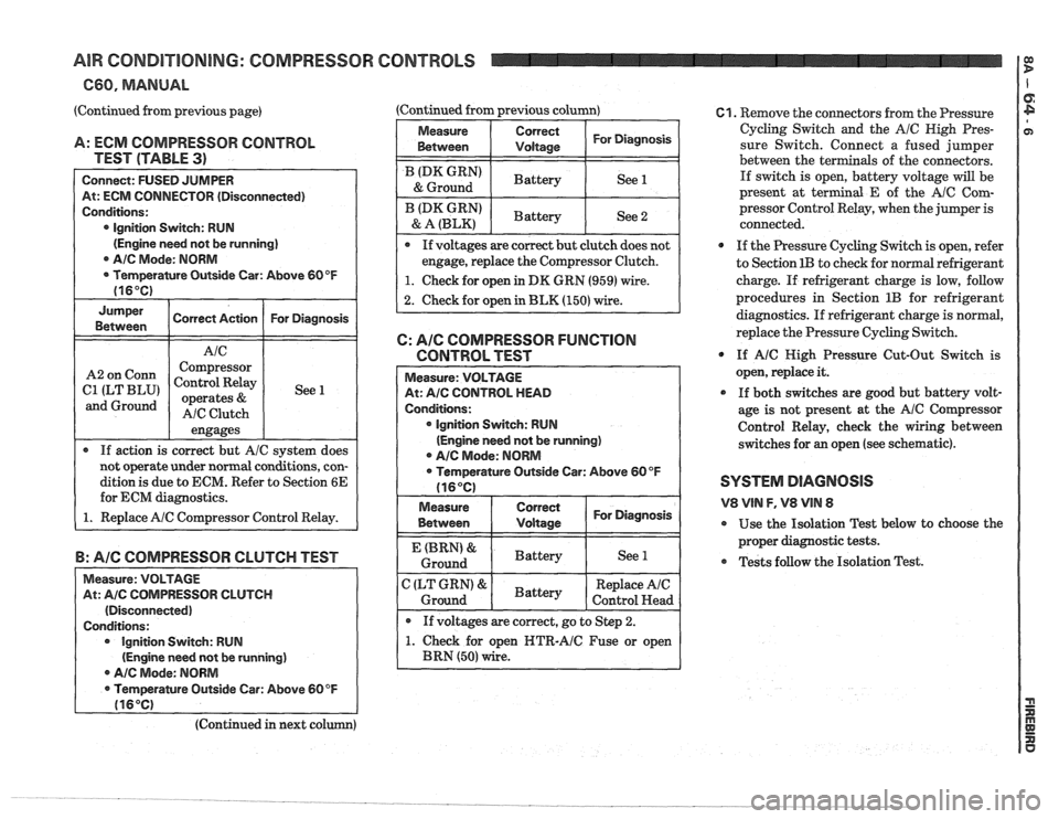
(Continued from previous page)
A: ECM COMPRESSOR CONTROL
TEST (TABLE
3)
Connect: FUSED JUMPER
At: ECM CONNECTOR (Disconnected)
Conditions:
0 Ignition Switch: RUN
(Engine need not be running]
AIC Mode: NORM
Temperature Outside Car: Above 60 OF
(16°C)
Jumper
Correct Action For Diagnosis
Between
engages
r If action is correct but A/C system does
not operate under normal conditions, con-
dition
is due to ECM. Refer to Section 6E
for ECM diagnostics.
1. Replace AIC Compressor Control Relay.
Corm
ILT BLU'
and Ground
B: AIC COMPRESSOR CLUTCH TEST
Measure: VOLTAGE
At:
AIC COMPRESSOR CLUTCH
(Disconnected)
Conditions: Ignition Switch: RUN
(Engine need not
be running)
r Ale Mode: NORM
Temperature Outside Car: Above
60 OF
116OC)
Compressor
Control Relay
operates
&
AIC Clutch (Continued from previous column)
1
See 1
Measure
I Between Correct I For
Diagnosis I I Vdtaas
/ (DK GRN' I Battery I See 1 & Ground
I BLz,",":' ( Battery I See 2
If voltages are correct hut clutch does not
engage, replace the Compressor Clutch.
I 1. Check for open in DK GRN (959) wire. 1
2. Check for open in BLK (150) wire.
C: AIC COMPRESSOR FUNCTION
CONTROL TEST
lgnition Switch: RUN
(Engine need not be running)
A/C Mode: NORM
open NTR-AIC Fuse or open
61. Remove the connectors from the Pressure
Cycling Switch and the
A/C High Pres-
sure Switch. Connect a fused jumper
between the ter
als of the connectors.
If switch is open, battery voltage will be
present at terminal
E of the AlC Com-
pressor Control Relay, when the jumper is
connected.
0 If the Pressure Cycling Switch is open, refer
to Section
1B to check for normal refrigerant
charge. If refrigerant charge is low, follow
procedures in Section
1B for refrigerant
diagnostics.
If refrigerant charge is normal,
replace the Pressure Cycling Switch.
@ If A/C High Pressure Cut-Out Switch is
open, replace it.
0 If both switches are good but battery volt-
age is not present at the
AIC Compressor
Control Relay, check the wiring between
switches for
an open (see schematic).
SYSTEM DIAGNOSIS
V8 VlN F, V8 VIN 8
@ Use the Isolation Test below to choose the
proper diagnostic tests.
Tests follow the Isolation Test.
(Continued in next co