1988 PONTIAC FIERO wiring
[x] Cancel search: wiringPage 1600 of 1825
LIGHTING SYSTEMS AND HORNS 8B-I
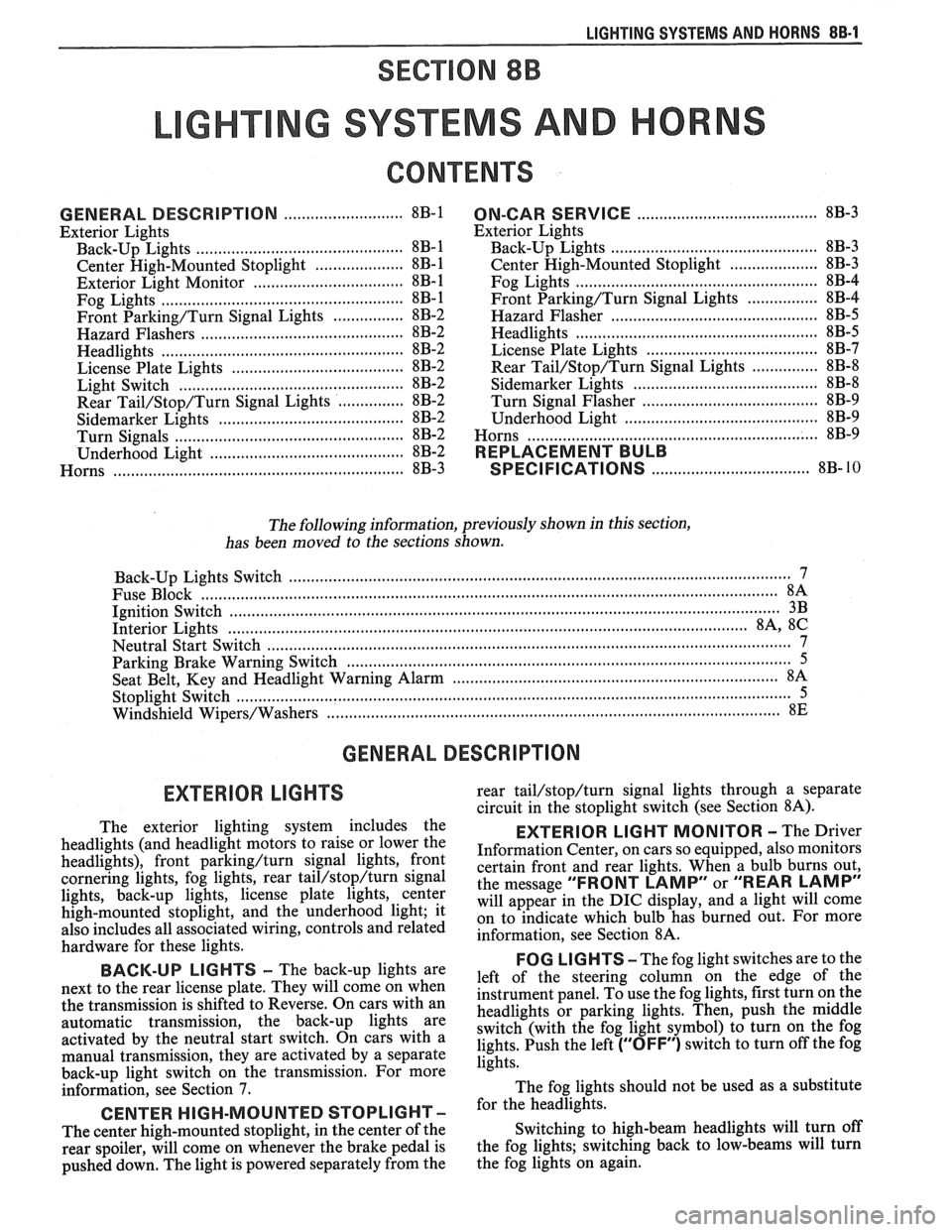
SECTION 8B
NG SYSTEMS AND HORNS
CONTENTS
........................... GENERAL DESCRIPTION 8B-1
Exterior Lights
....................... ................... Back-up Lights .. 8B- 1
Center High-Mounted Stoplight .................... 8B-1
Exterior Light Monitor .................................. 8B-1
............................ .................... Fog Lights .. 8B-1
Front Parking/Turn Signal Lights ................ 8B-2
............................... Hazard Flashers .. ........ 8B-2 .................................................... Headlights 8B-2
License Plate Lights ..................................... 8B-2
Light Switch ............................................... 8B-2
............... Rear Tail/Stop/Turn Signal Lights 8B-2
Sidemarker Lights ........................................ 8B-2
Turn Signals .......................................... 8B-2
......................... Underhood Light ... ........ 8B-2
Horns .......................................................... 8B-3
....................................... ON-CAR SERVICE 8B-3
Exterior Lights
............................................. Back-up Lights 8B-3
Center High-Mounted Stoplight .................... 8B-3
Fog Lights .................................................... 8B-4
Front Parking/Turn Signal Lights ................ 8B-4
Hazard Flasher .............................................. 8B-5
....................................................... Headlights 8B-5
License Plate Lights ..................................... 8B-7
............... Rear Tail/Stop/Turn Signal Lights 8B-8
.......................................... Sidemarker Lights 8B-8
................... ............... Turn Signal Flasher .. 8B-9
......................................... Underhood Light 8B-9
Horns ................................................................. 8B-9
REPLACEMENT BULB
.................................... SPECIFICATIONS 8B- 10
The following information, previously shown in this section,
has been moved to the sections shown.
Back-up Lights Switch
............................. ... ............................................................................ 7
................................................................................................................................. Fuse Block 8A
Ignition Switch ........................................................................................................................... 3B
Interior Lights
................................................................................................................... 8A, 8C
Neutral Start Switch ..................................................................................................................... 7
Parking Brake Warning Switch
......................... ... .................................................................... 5
........................................................................ Seat Belt, Key and Headlight Warning Alarm 8A
Stoplight Switch .......................... .. ............................................................................................... 5
Windshield
Wipers/Washers .................................................................................................... 8E
GENERAL DESCRIPTION
The exterior lighting system includes the
headlights (and headlight motors to raise or lower the
headlights), front
parkinghurn signal lights, front
cornering lights, fog lights, rear
tail/stop/turn signal
lights, back-up lights, license plate lights, center
high-mounted stoplight, and the underhood light; it
also includes all associated wiring, controls and related
hardware for these lights.
BACK-UP LIGHTS - The back-up lights are
next to the rear license plate. They will come on when
the transmission is shifted to Reverse. On cars with an
automatic transmission, the back-up lights are
activated by the neutral start switch. On cars with a
manual transmission, they are activated by a separate
back-up light switch on the transmission. For more
information, see Section 7.
CENTER HIGH-MOUNTED STOPLIGHT-
The center high-mounted stoplight, in the center of the
rear spoiler, will come on whenever the brake pedal is
pushed down. The light is powered separately from the rear
tail/stop/turn signal
lights through a separate
circuit in the stoplight switch (see Section
8A).
EXTERIOR LIGHT MONITOR - The Driver
Information Center, on cars so equipped, also monitors
certain front and rear lights. When a bulb burns out,
the message
"FRONT LAMP" or "REAR LAMP"
will appear in the DIC display, and a light will come
on to indicate which bulb has burned out. For more
information, see Section
8A.
FOG LIGHTS -The fog light switches are to the
left of the steering column on the edge of the
instrument panel. To use the fog lights, first turn on the
headlights or parking lights. Then, push the middle
switch (with the fog light symbol) to turn on the fog
lights. Push the left
("OFF") switch to turn off the fog
lights.
The fog lights should not be used as a substitute
for the headlights.
Switching to high-beam headlights will turn off
the fog lights; switching back to low-beams will turn
the fog lights on again.
Page 1602 of 1825
LIGHTING SYSTEMS AND HORNS 8B-3
HORNS the steering wheel sounds the horn by closing the horn
relay (in the convenience center behind the instrument
panel, to the right of the steering column). The horns
The holm(§) are mounted behind the front fascia use a solenoid-operated diaphragm to generate sound.
on the driver's side. $ushing the pad in the center of See Section 8A-40 for wiring and circuit information.
ON-CAR SERVICE
Wiring diagrams and other diagnosis information
is given in Section
8A. Information on properly
repairing wiring harnesses, connectors, etc., is on
8A-5.
Most lighting problems are caused by loose
connectors, open or shorted wiring, burned-out bulbs,
bad switches, inadequate ground or blown fuses. Many
of these require only replacement of a defective part.
When replacing a part that requires a special procedure
(such as a lens and housing assembly sealed together),
follow the instructions normally included in the
replacement parts package.
When removing a part that requires special
sealing items (such as sealing washers), be sure to
reinstall those items when replacing the part. Also, if
any body sealing items (grommets, etc.) are disturbed,
be sure to repair them so the passenger compartment
remains properly sealed.
EXTERlOR LIGHTS
BACK-UP LIGHTS
Fig. 8B-8
Replacement Bulb: Trade No. 1156, 32
Candlepower
To replace a back-up light bulb, see "Rear
Tail/Stop/Turn Signal Lights9' in this section. For
information on the back-up light switch on the
transmission, see Section
7.
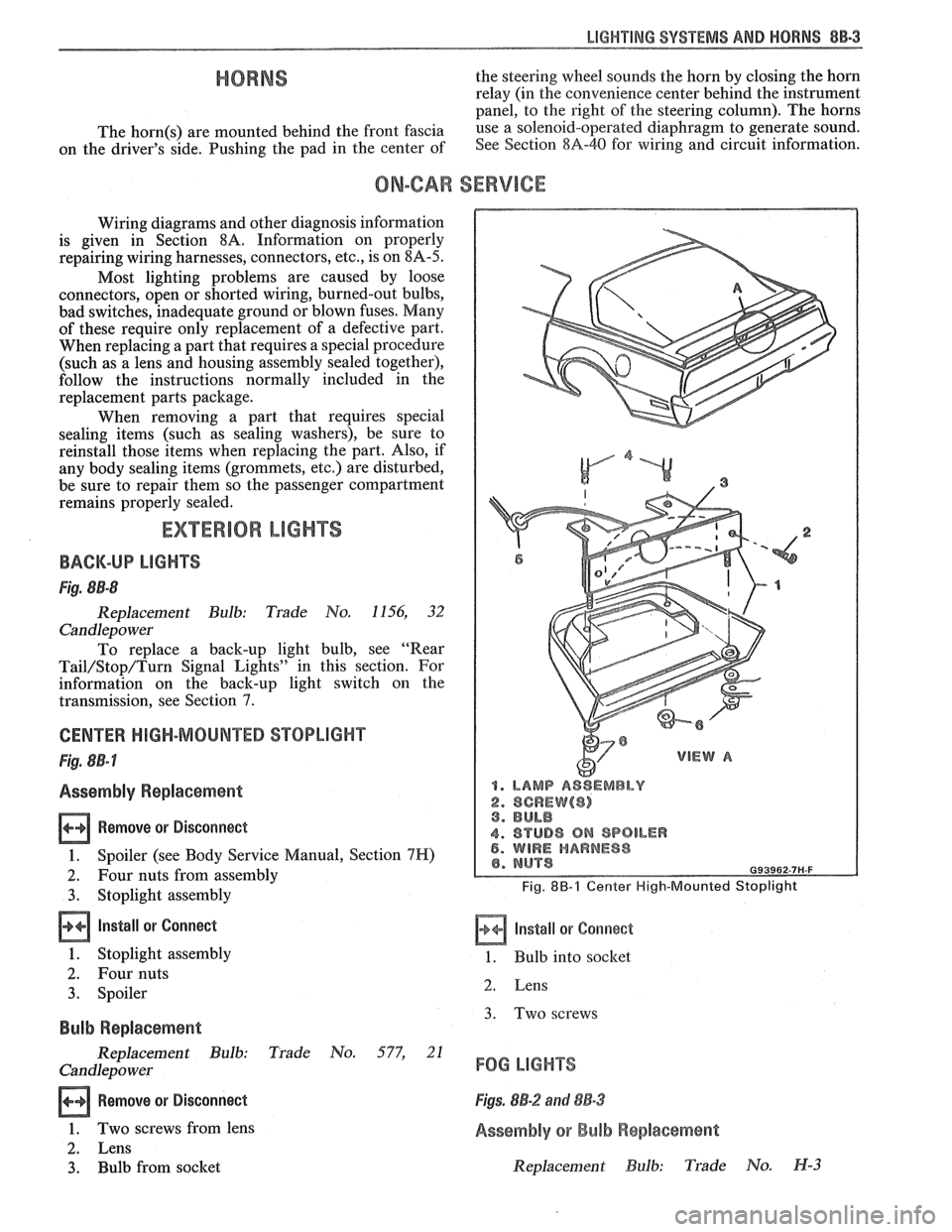
CENTER HIGH-MOUNTED STOPLIGHT
Fig. 8B-7
Assembly Replacement
Remove or Disconnect
1. Spoiler (see Body Service Manual, Section 7H)
2. Four nuts from assembly
3. Stoplight assembly
Install or Connect
1. Stoplight assembly
2. Four nuts
3. Spoiler
Bulb Replacement
Replacement Bulb: Trade No. 577, 21
Candlepo wer
Remove or Disconnect
1. Two screws from lens
2. Lens
3. Bulb from socket
1. LAMP ASSEMBLY
2. SCREW($) 3. BULB
4. STUD8 ON SPOILER 5. WIRE HARNESS
Fig. 8B-1 Center High-Mounted Stoplight
Install or Corrnect
1. Bulb into socket
2. Lens
3. Two screws
FOG LIGHTS
Figs. 8B-2 and 88-3
Assembly or Bulb Replacement
Replacement Bulb: Trade No. H-3
Page 1610 of 1825
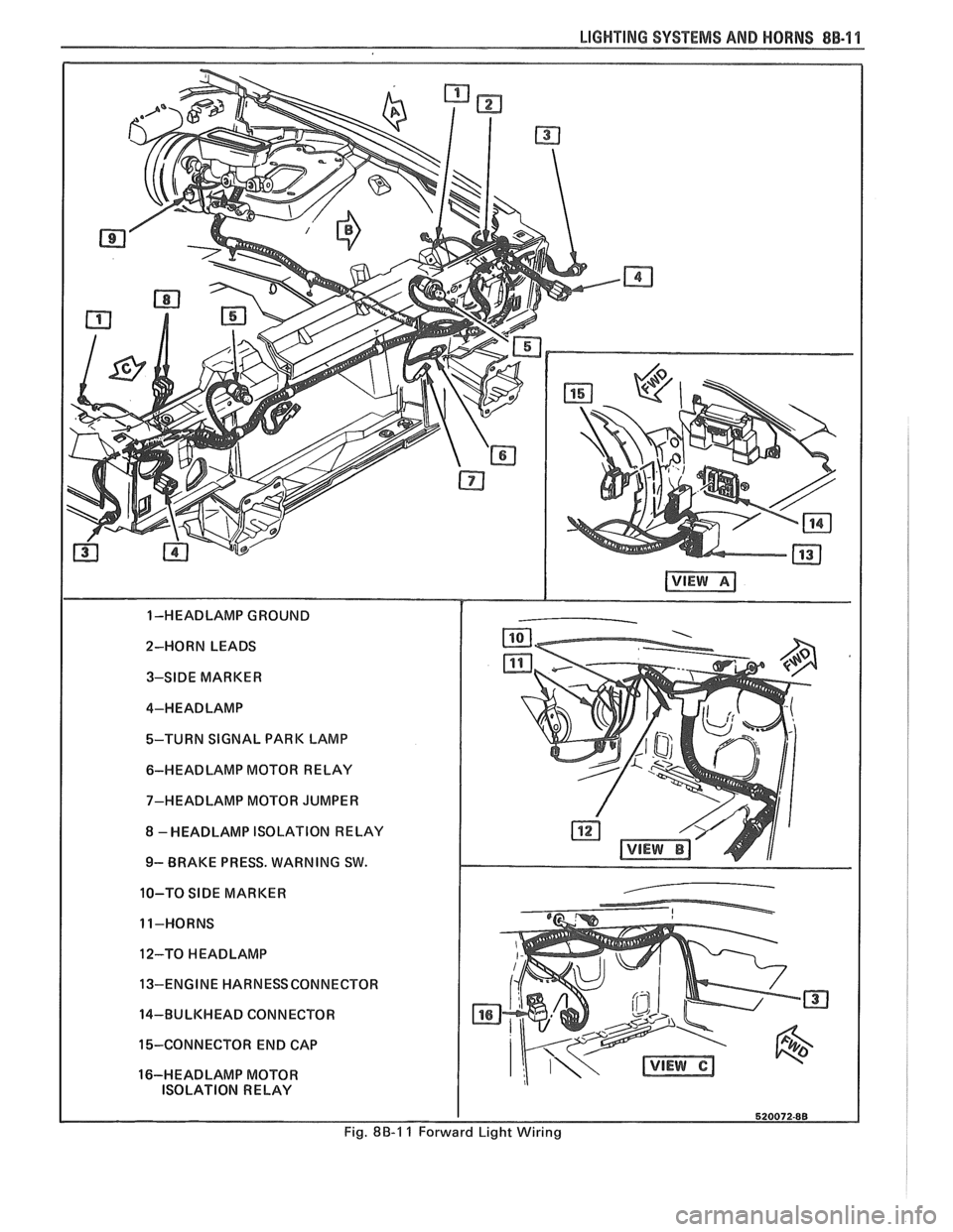
LIGHTING SYSTEMS AND HORNS 8B-11
2-HORN LEADS 3-SIDE MARKER
4-HEADLAMP
%-TURN SIGNAL PARK LAMP
6-HEADLAMP MOTOR RELAY
7-HEADLAMP MOTOR JUMPER
8 -HEADLAMP ISOLATION RELAY
9- BRAKE PRESS. WARNING SW.
10-TO
SIDE MARKER
11-HORNS
12-TO
HEADLAMP
13-ENGINE HARNESSCONNECTOR
14-BULKHEAD CONNECTOR
15-CONNECTOR END CAP
16-HEADLAMP MOTOR ISOLATION RELAY
Fig. 8B-1 1 Forward Light Wiring
Page 1612 of 1825
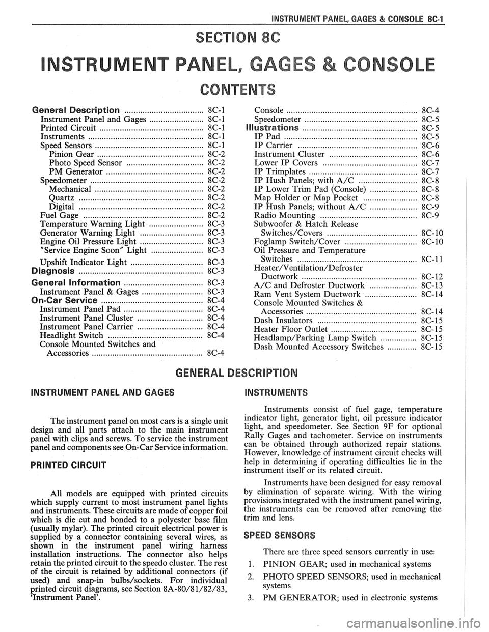
INSTRUMENT PANEL, GAGES & CONSOLE 8C-'I
SECTION 8C
NSTRUMENT PANEL, GAGES & CONSOLE
CONTENTS
General Description ................................... 8C-1
Instrument Panel and Gages ........................ 8C-1
Printed Circuit .......................................... 8C-1
Instruments ................................................... 8C- 1
Speed Sensors
............................ .. ............. 8C- 1
Pinion Gear
............................................. 8C-2
Photo Speed Sensor ................................ 8C-2
PM Generator ................... .. ...... ............... 8C-2
Speedometer ................................................ 8C-2
Mechanical ....................... .. .................... 8C-2
Quartz ........................ .. .......................... 8C-2
Digital .................... .. ...... ................. 8C-2
Fuel Gage .................................................... 8C-2
Temperature Warning Light ...................... 8C-3
Generator Warning Light ............................ 8C-3
Engine Oil Pressure Light ............................ 8C-3
"Service Engine Soon" Light ....................... 8C-3
Upshift Indicator Light .............................. 8C-3
Diagnosis .................... .. ........................... 8C-3
General Information .................................. 8C-3
Instrument Panel & Gages ...................... ..... 8C-3
On-Car Service ......................... .. ........... 8C-4
Instrument Panel Pad ................................... 8C-4
Instrument Panel Cluster ........................... 8C-4
Instrument Panel Carrier ............................. 8C-4
Headlight Switch .......................................... 8C-4
Console Mounted Switches and
Accessories
............................................... 8C-4
Console ......................................................... 8C-4
Speedometer .................................................. 8C-5
Illustra3ions ................................................. 8C-5
IP Pad ........................................................... 8C-5
IP Carrier ................................................... 8C-6
Instrument Cluster ....................................... 8C-6
Lower IP Covers ......................................... 8C-7
IP Trimplates ............................................... 8C-7
IP Hush Panels; with A/C .......................... 8C-8
..................... IP Lower Trim Pad (Console) 8C-8
Map Holder or Map Pocket ........................ 8C-8
IP Hush Panels; without A/C ..................... 8C-9
Radio Mounting ........................................... 8C-9
Subwoofer & Hatch Release
Switches/Covers ........................................ 8C- 10
Foglamp Switch/Cover ................................ 8C- 10
Oil Pressure and Temperature
Switches
..................................................... 8C-11
Heater/Ventilation/Defroster
Ductwork .................................................. 8C- 12
A/C and Defroster Ductwork ..................... 8C-13
Ram Vent System Ductwork ....................... 8C-14
Console Mounted Switches
&
Accessories ................................................. 8C- 14
Dash Insulators
............................................ 8C- 15
Heater Floor Outlet
..................................... 8C-15
................ Headlamp/Parking Lamp Switch 8C- 15
............. Dash Mounted Accessory Switches 8C- 15
GENERAL DESCRIPTION
INSTRUMENT PANEL AND GAGES
INSTRUMENTS
Instruments consist of fuel gage, temperature
The instrument panel on most cars is a sing,e unit indicator light, generator light, oil pressure indicator
design and all parts attach to the main instrument light, and speedometer. See Section 9F for optional
panel with clips and screws. To service the instrument Gages and tachometer. Service on instruments
panel and components see on-car service information, can be obtained through authorized repair stations.
However, knowledge of instrument circuit checks will
PRINTED CIRCUIT
All models are equipped with printed circuits
which supply current to most instrument panel lights
and instruments. These circuits are made of copper foil
which is die cut and bonded to a polyester base film
(usually mylar). The printed circuit electrical power is
supplied by a connector containing several wires, as
shown in the instrument panel wiring harness
installation instructions. The connector also helps
retain the printed circuit to the speedo cluster. The rest
of the circuit is retained by additional connectors (if
used) and snap-in
bulbs/sockets. For individual
printed circuit diagrams, see Section
8A-80/8 1/82/83,
'Instrument Panel'. help
in determining if operating difficulties lie in the
instrument itself or its related circuit.
Instruments have been designed for easy removal
by elimination of separate wiring. With the wiring
provisions integrated with the instrument panel wiring,
the instruments can be removed after removing the
trim and lens.
SPEED SENSORS
There are three speed sensors currently in use:
1. PINION GEAR; used in mechanical systems
2. PHOTO SPEED SENSORS; used in mechanical
systems
3. PM GENERATOR; used in electronic systems
Page 1614 of 1825
INSTRUMENT PANEL. GAGES & CONSOLE 8C-3
tank only when ignition switch is turned to "ON" or
"ACCESSORY" positions.
When ignition is turned to "OFF" or "START"
positions, the pointer may come to rest at any position.
The letters
"E" and "F" on the fuel gage are used to
point out direction of indicator travel only.
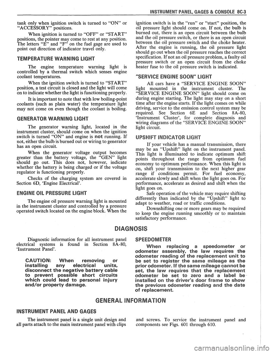
TEMPERATURE WARNING LIGHT
The engine temperature warning light is
controlled by a thermal switch which senses engine
coolant temperatures.
When the ignition switch is turned to "START"
position, a test circuit is closed and the light will come
on to indicate whether the light is functioning properly.
It is important to note that with low boiling-point
coolants (such as plain water) the temperature light
may not come on even though the coolant is boiling.
GENERATOR WARNING LIGHT
The generator warning light, located in the
instrument cluster, should come on when the ignition
switch is turned
"ON" and engine is not running. If
not, either the bulb is burned out or wiring to generator
has an open circuit.
When the generator voltage output becomes
greater than the battery voltage, the
"GEN" light
should go out. This does not, however, indicate
whether the battery is being charged or if the voltage
regulator is functioning properly.
Checks of the charging system are covered in
Section 6D, 'Engine Electrical'.
ENGINE OIL PRESSURE LIGHT
The engine oil pressure warning light is mounted
in the instrument cluster and controlled by a pressure
operated switch located on the engine block. When the ignition switch is
in the
"run" or "start9' position, the
oil pressure light should come on. If not, the bulb is
burned out, there is an open circuit between the bulb
and the oil pressure switch, or there is an open circuit
between the oil pressure switch and the choke heater.
After the engine is running, the oil pressure light
should go out when the oil pressure reaches the correct
specification. If not an oil pressure problem, a faulty oil
pressure switch or an open circuit from the choke
heater fuse to the oil pressure switch is indicated.
"SERVICE ENGINE SOON" LIGHT
All cars have a "SERVICE ENGINE SOON"
light mounted in the instrument cluster. The
"SERVICE ENGINE SOON9' light should come on
during engine starting. The light may stay on
a short
time after the engine starts.
If the light comes on while
driving, service to the emission control system may be
required. See Section
6E and Section 8A-80,
'Instrument Cluster', for complete diagnosis and
wiring diagrams of the
""P;RVICE ENGINE SOON"
light circuit.
UPSHIFT INDICATOR LIGHT
If your vehicle has a manual transmission, there
may be an
''Upshift" light on the instrument panel.
This light is illuminated to indicate optimum shift
points throughout the range from optimum fuel
economy to optimum performance. When this light is
on, shift your transmission to the next higher gear
range if conditions permit. For fuel economy,
accelerate slowly and shift when the light goes on. For
performance, accelerate as desired and shift when the
light goes on.
Safe operation of the vehicle may require shifting
differently than indicated by the "Upshift" light to
adapt to weather, road or traffic conditions.
Downshifting one or more gears may be required
to keep the engine running smoothly or to maintain
satisfactory performance.
DIAGNOSIS
Diagnostic information for all instrument panel
electrical systems is found in Section
8A-80,
'Instrument Panel'.
CAUTION: When removing or
installing any electrical units,
disconnect the negative battery cable
to prevent possible short circuits
which could lead to personal injury
and/or property damage. When
replacing a speedometer or
odometer assembly, the law requires the
odometer reading of the replacement unit to
be set to register the same mileage as the
prior odometer.
if the same mileage cannot be
set, the
law requires that the replacement
odometer be set to zero and a label be
installed on the driver's door frame to show
the previous odometer reading and the date
of replacement.
GENERAL BNFORMATlOM
INSTRUMENT PANEL AND GAGES
The instrument panel is a single unit design and
and screws. To service the instrument panel and
all parts attach to the main instrument panel with clips components see Figs. 601 through 610.
Page 1615 of 1825
8C.4 INSTRUMENT PANEL, GAGES & CONSOLE
ON-CAR SERVlCE
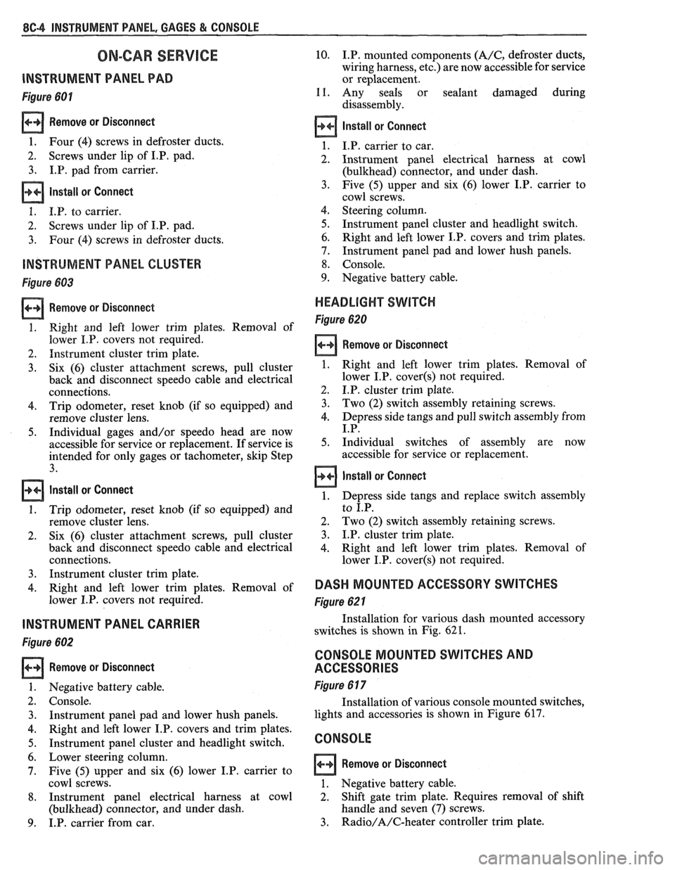
lNSTRUMEMT PANEL PAD
Figure 601
Remove or Disconnect
1. Four (4) screws in defroster ducts.
2. Screws
under lip of
I.P, pad.
3. I.P. pad from carrier.
lnstall or Connect
1. I.P. to carrier.
2. Screws
under lip of I.P. pad.
3. Four (4) screws in defroster ducts.
INSTRUMENT PANEL CLUSTER
Figure 683
Remove or Disconnect
1. Right and left lower trim plates. Removal of
lower I.P. covers not required.
2. Instrument cluster trim plate.
3. Six (6) cluster attachment screws, pull cluster
back and disconnect speedo cable and electrical
connections.
4. Trip odometer, reset knob (if so equipped) and
remove cluster lens.
5. Individual gages and/or speedo head are now
accessible for service or replacement. If service is
intended for only gages or tachometer, skip Step
3.
Install or Connect
1. Trip odometer, reset knob (if so equipped) and
remove cluster lens.
2. Six
(6) cluster attachment screws, pull cluster
back and disconnect speedo cable and electrical
connections.
3. Instrument cluster trim plate.
4. Right and left lower trim plates. Removal of
lower I.P. covers not required.
INSTRUMENT PANEL CARRIER
Figure 602
Remove or Disconnect
Negative battery cable.
Console. Instrument panel pad and lower hush panels.
Right and left lower I.P. covers and trim plates.
Instrument panel cluster and headlight switch.
Lower steering column.
Five (5) upper and six (6) lower I.P. carrier to
cowl screws.
Instrument panel electrical harness at cowl
(bulkhead) connector, and under dash.
I.P. carrier from car.
10. I.P. mounted components (A/C, defroster ducts,
wiring harness, etc.) are now accessible for service
or replacement.
11. Any seals or sealant damaged during
disassembly.
Install or Connect
I.P. carrier to car.
Instrument panel electrical harness at cowl
(bulkhead) connector, and under dash.
Five (5) upper and six (6) lower I.P. carrier to
cowl screws.
Steering column.
Instrument panel cluster and headlight switch.
Right and left lower I.P. covers and trim plates.
Instrument panel pad and lower hush panels.
Console.
Negative battery cable.
HEADLIGHT SWITCH
Figure 620
Remove or Disconnect
1. Right and left lower trim plates. Removal of
lower I.P.
cover(s) not required.
2. I.P. cluster trim plate.
3. Two (2) switch assembly retaining screws.
4. Depress side tangs and pull switch assembly from
I.P.
5. Individual switches of assembly are now
accessible for service or replacement.
Install or Connect
1. Depress side tangs and replace switch assembly
to I.P.
2. Two
(2) switch assembly retaining screws.
3. I.P. cluster trim plate.
4. Right and
left lower trim plates. Removal of
lower I.P.
cover(s) not required.
DASH MOUNTED ACCESSORY SWITCHES
Figure 62 1
Installation for various dash mounted accessory
switches is shown in Fig.
62 1.
CONSOLE MOUNTED SWITCHES AND
ACCESSORIES
Figure 6 17
Installation of various console mounted switches,
lights and accessories is shown in Figure 617.
CONSOLE
Remove or Disconnect
1. Negative battery cable.
2. Shift gate trim plate. Requires removal
of shift
handle and seven (7) screws.
3. Radio/A/C-heater controller trim plate.
Page 1629 of 1825
8E -2 WINDSHIELD WIPER SYSTEMS F CARLINE
brush circuit (Fig. 12) is completed to the (+) 12 volts
DC source and the wiper motor runs at that particular
speed setting.
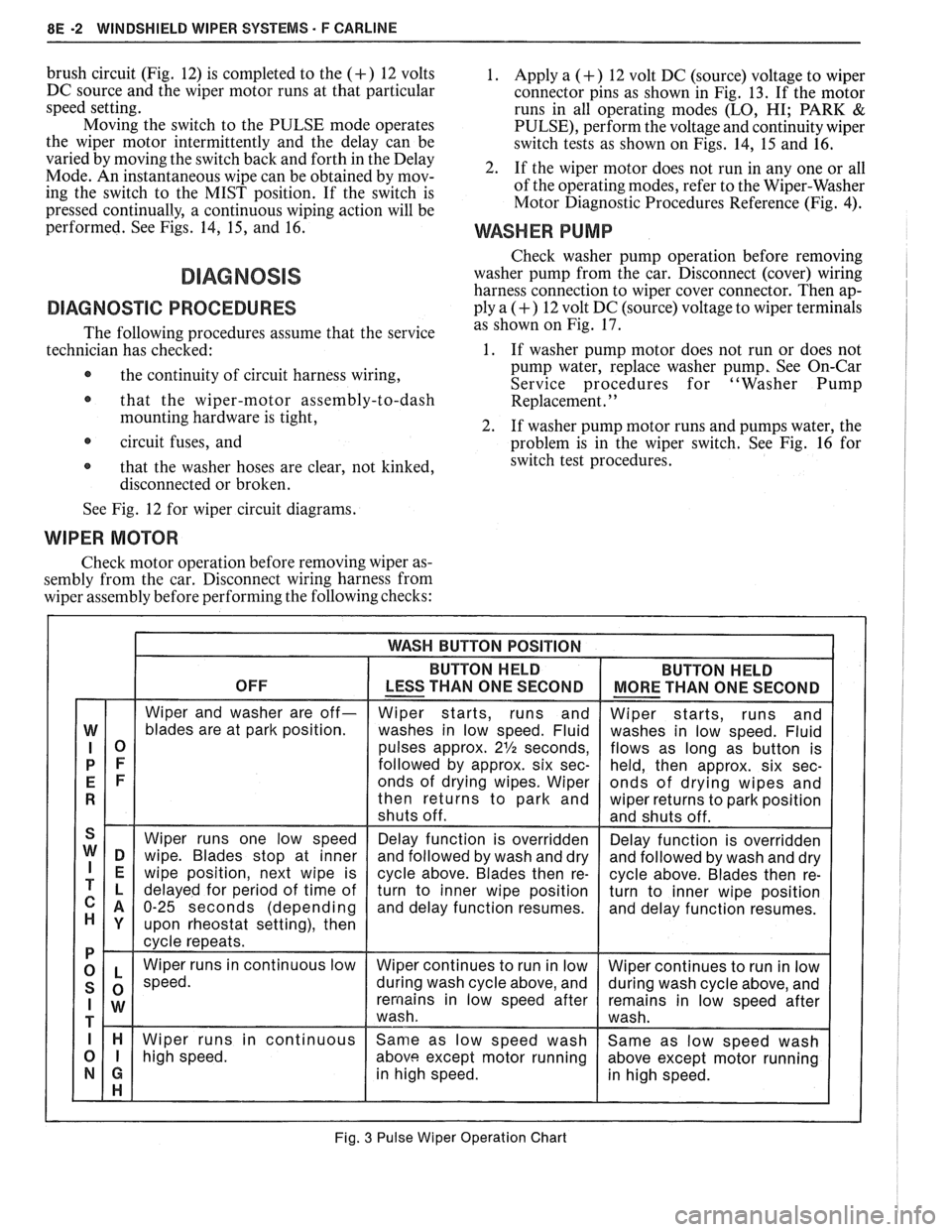
Moving the switch to the PULSE mode operates
the wiper motor intermittently and the delay can be
varied by moving the switch back and forth in the Delay
Mode. An instantaneous wipe can be obtained by mov-
ing the switch to the MIST position. If the switch is
pressed continually, a continuous wiping action will be
performed. See Figs. 14,
15, and 16.
DIAGNOSVC PROCEDURES
The following procedures assume that the service
technician has checked:
@ the continuity of circuit harness wiring,
@ that the wiper-motor assembly-to-dash
mounting hardware is tight,
circuit fuses, and
@ that the washer hoses are clear, not kinked,
disconnected or broken.
1. Apply a (+) 12 volt DC (source) voltage to wiper
connector pins as shown in Fig. 13. If the motor
runs in all operating modes
(LO, HI; PARK &
PULSE), perform the voltage and continuity wiper
switch tests as shown on Figs. 14, 15 and 16.
2. If the wiper motor does not run in any one or all
of the operating modes, refer to the Wiper-Washer
Motor Diagnostic Procedures Reference (Fig.
4).
WASHER PUMP
Check washer pump operation before removing
washer pump from the car. Disconnect (cover) wiring
harness connection to wiper cover connector. Then ap-
ply a
(+) 12 volt DC (source) voltage to wiper terminals
as shown on Fig. 17.
1. If washer pump motor does not run or does not
pump water, replace washer pump, See On-Car
Service procedures for "Washer Pump
Replacement.
' '
2. If washer pump motor runs and pumps water, the
problem is in the wiper switch. See Fig. 16 for
switch test procedures.
See Fig. 12 for wiper circuit diagrams.
WIPER MOTOR
Check motor operation before removing wiper as-
sembly from the car. Disconnect wiring harness from
wiper assembly before performing the following checks:
Fig. 3 Pulse Wiper Operation Chart
Page 1637 of 1825
BE -10 WINDSHIELD WIPER SYSTEMS - F CARLINE
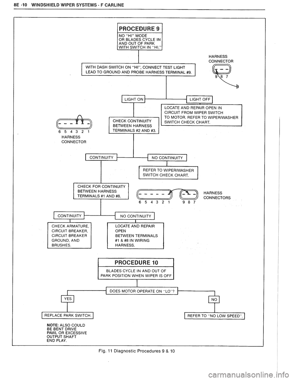
I PROCEDURE 9 1
I I HARNESS I CONNECTOR
(Q)
CIRCUIT FROM WIPER SWITCH
TO MOTOR. REFER TO
WlPERlWASHER CHECK CONTINUITY
BETWEEN HARNESS
HARNESS
CONNECTOR
I
REFER TO WlPERlWASHER
SWITCH CHECK CHART. I
HARNESS
CONNECTORS
654321 9 8 7
GROUND, AND EEN TERMINALS #l & #8 IN WIRING
BLADES
CYCLE IN AND OUT OF
DOES MOTOR OPERATE ON "LO"?
Fig. 11 Diagnostic Procedures 9 & 10